ABS FORD E150 1999 Owners Manual
[x] Cancel search | Manufacturer: FORD, Model Year: 1999, Model line: E150, Model: FORD E150 1999Pages: 208, PDF Size: 1.93 MB
Page 8 of 208
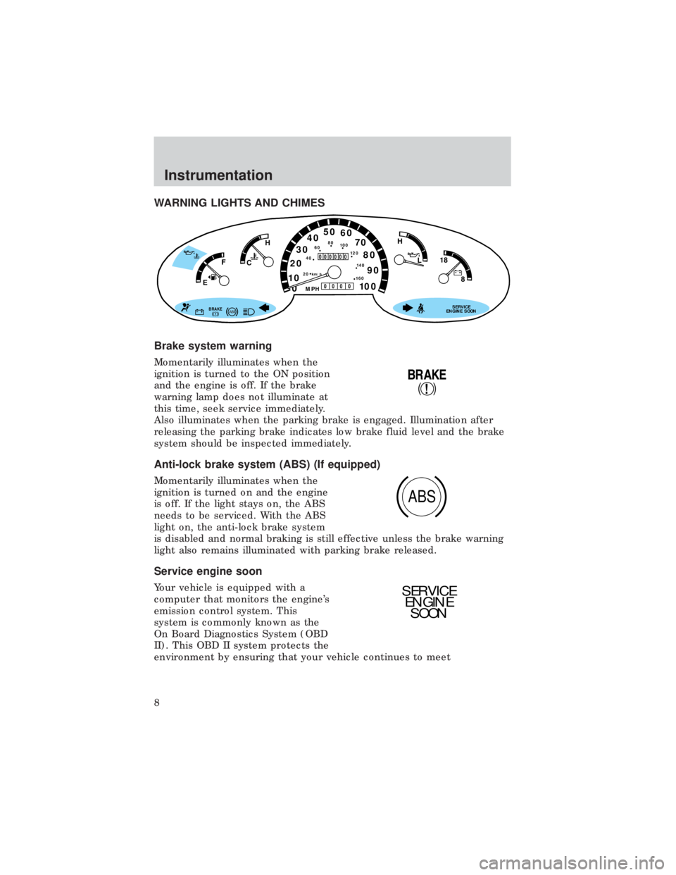
WARNING LIGHTS AND CHIMES
Brake system warning
Momentarily illuminates when the
ignition is turned to the ON position
and the engine is off. If the brake
warning lamp does not illuminate at
this time, seek service immediately.
Also illuminates when the parking brake is engaged. Illumination after
releasing the parking brake indicates low brake fluid level and the brake
system should be inspected immediately.
Anti-lock brake system (ABS) (If equipped)
Momentarily illuminates when the
ignition is turned on and the engine
is off. If the light stays on, the ABS
needs to be serviced. With the ABS
light on, the anti-lock brake system
is disabled and normal braking is still effective unless the brake warning
light also remains illuminated with parking brake released.
Service engine soon
Your vehicle is equipped with a
computer that monitors the engine's
emission control system. This
system is commonly known as the
On Board Diagnostics System (OBD
II). This OBD II system protects the
environment by ensuring that your vehicle continues to meet
0 1020304050
60
70
80
90
10 0
20 km/h
406080
10 0
12 0
14 0
H
L
16 0
MPH
000000
0000
BRAKE
18
8
SERVICE
ENGINE SOON
FH
C
E
!
BRAKE
ABS
SERVICE
ENGINE
SOON
Instrumentation
8
Page 103 of 208
BRAKES
Your service brakes are self-adjusting. Refer to the ªService Guideº for
scheduled maintenance.
Occasional brake noise is normal and often does not indicate a
performance concern with the vehicle's brake system. In normal
operation, automotive brake systems may emit occasional or intermittent
squeal or groan noises when the brakes are applied. Such noises are
usually heard during the first few brake applications in the morning;
however, they may be heard at any time while braking and can be
aggravated by environmental conditions such as cold, heat, moisture,
road dust, salt or mud. If a ªmetal-to-metal,º ªcontinuous grindingº or
ªcontinuous squealº sound is present while braking, the brake linings
may be worn-out and should be inspected by a qualified service
technician.
Four-wheel anti-lock brake system (ABS) (if equipped)
On vehicles equipped with an anti-lock braking system (ABS), a noise
from the hydraulic pump motor and pulsation in the pedal may be
observed during ABS braking events. Pedal pulsation coupled with noise
while braking under panic conditions or on loose gravel, bumps, wet or
snowy roads is normal and indicates proper functioning of the vehicle's
anti-lock brake system. If the vehicle has continuous vibration or shudder
in the steering wheel while braking, the vehicle should be inspected by a
qualified service technician.
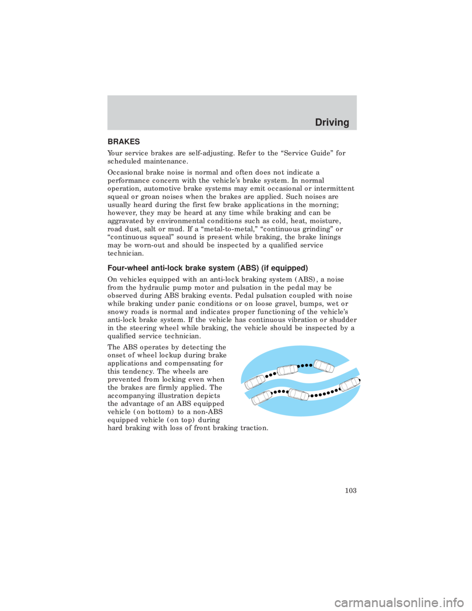
The ABS operates by detecting the
onset of wheel lockup during brake
applications and compensating for
this tendency. The wheels are
prevented from locking even when
the brakes are firmly applied. The
accompanying illustration depicts
the advantage of an ABS equipped
vehicle (on bottom) to a non-ABS
equipped vehicle (on top) during
hard braking with loss of front braking traction.
Driving
103
Page 104 of 208
ABS warning lamp
TheABSwarning lamp in the instrument cluster momentarily illuminates
when the ignition is turned on and the engine is off. If the light does not
illuminate momentarily at start up, remains on or continues to flash, the
ABS needs to be serviced.
With the ABS light on, the anti-lock
brake system is disabled and normal
braking is still effective unless the
brake warning light also remains
illuminated with parking brake
released. (If your brake warning lamp illuminates, have your vehicle
serviced immediately).
Using ABS
²In an emergency or when maximum efficiency from the ABS is
required, apply continuous full force on the brake. The ABS will be
activated immediately, thus allowing you to retain full steering control
of your vehicle and, providing there is sufficient space, will enable you
to avoid obstacles and bring the vehicle to a controlled stop.
²The Anti-Lock system does not decrease the time necessary to apply
the brakes or always reduce stopping distance. Always leave enough
room between your vehicle and the vehicle in front of you to stop.
²We recommend that you familiarize yourself with this braking
technique. However, avoid taking any unnecessary risks.
Rear anti-lock brake system (RABS) (if equipped)
Rear Anti-lock Brake System (RABS) is designed to help you maintain
directional stability in emergency stopping situations. With RABS, the
rear brakes are kept from locking during panic stops; however, the front
wheels can lock because they are not controlled by RABS.
A clicking noise and slight pedal pulsation during RABS braking events
indicates the RABS is functioning. Pedal pulsation coupled with clicking
noise while braking under panic conditions on loose gravel, wet or snowy
roads is normal and indicates proper functioning of the vehicle's RABS. If
the vehicle has continuous vibration or shudder in the steering wheel
while braking, the vehicle should be inspected by a qualified service
technician.
The RABS operates by detecting the onset of rear wheel lockup during
brake applications and compensating for this tendency.
!
BRAKE
Driving
104
Page 105 of 208
RABS warning lamp
TheABSwarning lamp in the instrument cluster illuminates if a RABS
fault is detected. Have your vehicle serviced as soon as possible.
Normal braking is still effective
unless the BRAKE warning lamp is
also illuminated.
Using RABS
²In an emergency, applying full pressure may cause the front wheels to
lock.If the front brakes lock, the vehicle cannot be steered.Yo u
should apply the brakes with steadily increasing force, as if
ªsqueezingº the brakes. If you feel the front wheels begin to lock,
momentarily release the pedal and repeat the ªsqueezeº technique.
²We recommend that you familiarize yourself with how the RABS
performs. However, avoid unnecessary risks.
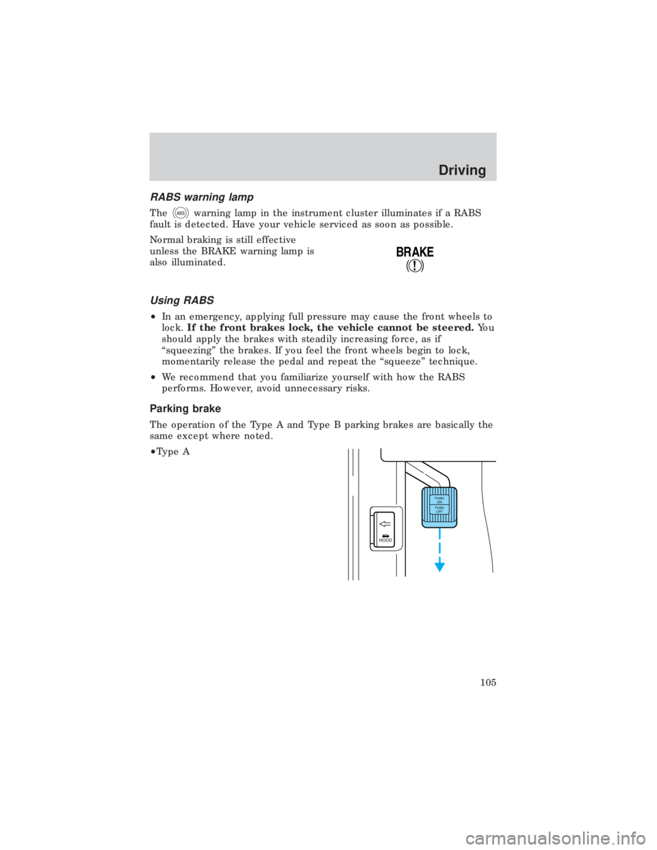
Parking brake
The operation of the Type A and Type B parking brakes are basically the
same except where noted.
²Type A
!
BRAKE
HOOD
PUSH
ON
PUSH
OFF
Driving
105
Page 127 of 208
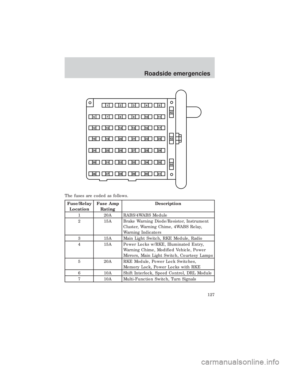
The fuses are coded as follows.
Fuse/Relay
LocationFuse Amp
RatingDescription
1 20A RABS/4WABS Module
2 15A Brake Warning Diode/Resistor, Instrument
Cluster, Warning Chime, 4WABS Relay,
Warning Indicators
3 15A Main Light Switch, RKE Module, Radio
4 15A Power Locks w/RKE, Illuminated Entry,
Warning Chime, Modified Vehicle, Power
Mirrors, Main Light Switch, Courtesy Lamps
5 20A RKE Module, Power Lock Switches,
Memory Lock, Power Locks with RKE
6 10A Shift Interlock, Speed Control, DRL Module
7 10A Multi-Function Switch, Turn Signals
1234
5
7
689101142
43
44 13 12 14
15 16 17
19 18
2021 22 23
25 24
26 27 28 29
31 30 32 33 3435
37
3638 3940
41
Roadside emergencies
127
Page 128 of 208
Fuse/Relay
LocationFuse Amp
RatingDescription
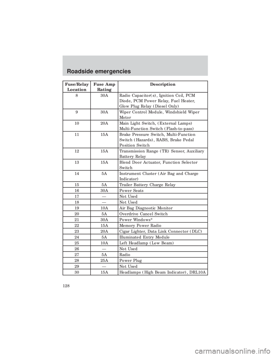
8 30A Radio Capacitor(s), Ignition Coil, PCM
Diode, PCM Power Relay, Fuel Heater,
Glow Plug Relay (Diesel Only)
9 30A Wiper Control Module, Windshield Wiper
Motor
10 20A Main Light Switch, (External Lamps)
Multi-Function Switch (Flash-to-pass)
11 15A Brake Pressure Switch, Multi-Function
Switch (Hazards), RABS, Brake Pedal
Position Switch
12 15A Transmission Range (TR) Sensor, Auxiliary
Battery Relay
13 15A Blend Door Actuator, Function Selector
Switch
14 5A Instrument Cluster (Air Bag and Charge
Indicator)
15 5A Trailer Battery Charge Relay
16 30A Power Seats
17 Ð Not Used
18 Ð Not Used
19 10A Air Bag Diagnostic Monitor
20 5A Overdrive Cancel Switch
21 30A Power Windows*
22 15A Memory Power Radio
23 20A Cigar Lighter, Data Link Connector (DLC)
24 5A Illuminated Entry Module
25 10A Left Headlamp (Low Beam)
26 Ð Not Used
27 5A Radio
28 25A Power Plug
29 Ð Not Used
30 15A Headlamps (High Beam Indicator), DRL10A
Roadside emergencies
128
Page 131 of 208
Fuse/Relay
LocationFuse Amp
RatingDescription
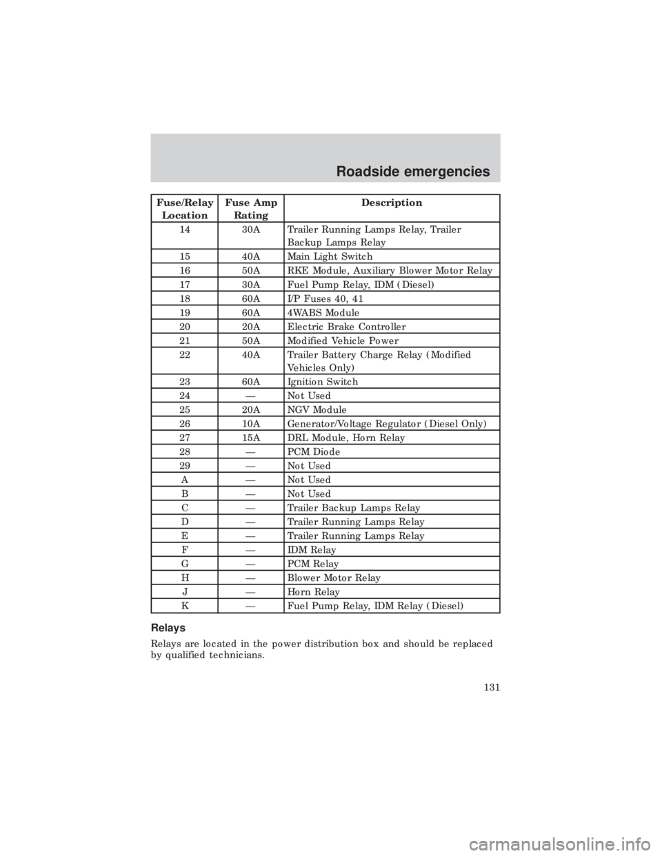
14 30A Trailer Running Lamps Relay, Trailer
Backup Lamps Relay
15 40A Main Light Switch
16 50A RKE Module, Auxiliary Blower Motor Relay
17 30A Fuel Pump Relay, IDM (Diesel)
18 60A I/P Fuses 40, 41
19 60A 4WABS Module
20 20A Electric Brake Controller
21 50A Modified Vehicle Power
22 40A Trailer Battery Charge Relay (Modified
Vehicles Only)
23 60A Ignition Switch
24 Ð Not Used
25 20A NGV Module
26 10A Generator/Voltage Regulator (Diesel Only)
27 15A DRL Module, Horn Relay
28 Ð PCM Diode
29 Ð Not Used
A Ð Not Used
B Ð Not Used
C Ð Trailer Backup Lamps Relay
D Ð Trailer Running Lamps Relay
E Ð Trailer Running Lamps Relay
F Ð IDM Relay
G Ð PCM Relay
H Ð Blower Motor Relay
J Ð Horn Relay
K Ð Fuel Pump Relay, IDM Relay (Diesel)
Relays
Relays are located in the power distribution box and should be replaced
by qualified technicians.
Roadside emergencies
131
Page 171 of 208
²Avoid inhaling fuel vapors. Inhaling too much fuel vapor of any kind
can lead to eye and respiratory tract irritation. In severe cases,
excessive or prolonged breathing of fuel vapor can cause serious
illness and permanent injury.
²Avoid getting fuel liquid in your eyes. If fuel is splashed in the eyes,
remove contact lenses (if worn), flush with water for 15 minutes and
seek medical attention. Failure to seek proper medical attention could
lead to permanent injury.
²Fuels can also be harmful if absorbed through the skin. If fuel is
splashed on the skin and/or clothing, promptly remove contaminated
clothing and wash skin thoroughly with soap and water. Repeated or
prolonged skin contact with fuel liquid or vapor causes skin irritation.
²Be particularly careful if you are taking ªAntabuseº or other forms of
disulfiram for the treatment of alcoholism. Breathing gasoline vapors,
or skin contact could cause an adverse reaction. In sensitive
individuals, serious personal injury or sickness may result. If fuel is
splashed on the skin, promptly wash skin thoroughly with soap and
water. Consult a physician immediately if you experience an adverse
reaction.
Choosing the right fuel
Use only UNLEADED FUEL. The use of leaded fuel is prohibited by law
and could damage your vehicle.
Do not use gasolines containing methanol. It can damage critical fuel
systems components.
Vehicles certified to meet California emission standards (indicated on the
underhood Vehicle Emissions Control Information label) are designed to
operate on California cleaner-burning, low-sulfur gasolines. If you have a
California-certified vehicle and California cleanerÐburning gasoline is not
available when you refuel, your engine should perform adequately.
However, the performance of the emission control devices and systems
may be adversely affected. In New York and Massachusetts, which have
adopted California's emission standards without requiring the sale of
California cleaner-burning gasoline, repairs to correct the effects of using
non-California fuel may not be covered by the emissions warranty.
Your vehicle was not designed to use fuel or fuel additives with metallic
compounds, including manganese-based compounds containing (MMT).
Repairs to correct the effects of using a fuel for which your vehicle was
not designed may not be covered by your warranty.
Maintenance and care
171
Page 173 of 208
²Your ªService Engine Soonº light may come on. For more information
on the ªService Engine Soonº light, refer to theInstrumentation
chapter.
Fuel Filler Cap
Your fuel tank filler cap has an indexed design with a one-eighth turn
on/off feature.
When fueling your vehicle:
1. Turn the engine off.
2. Carefully turn the filler cap counterclockwise 1/8 of a turn until it
stops.
3. Pull to remove the cap from the fuel filler pipe.
4. To install the cap, align the tabs on the cap with the notches on the
filler pipe.
5. Turn the filler cap clockwise 1/8 of a turn until it stops.
If the ªService Engine Soon/Check Engine ª indicator comes on and stays
on when you start the engine, the fuel filler cap may not be properly
installed. Turn off the engine, remove the fuel filler cap and reinstall it
being careful to align the cap properly.
If you must replace the fuel filler cap, replace it with a genuine
Ford or Motorcraft part. The customer warranty may be void for
any damage to the fuel tank or fuel system if a genuine Ford or
Motorcraft fuel filler cap is not used.
The fuel system may be under pressure. If the fuel filler cap is
venting vapor or if you hear a hissing sound, wait until it stops
before completely removing the fuel filler cap. Otherwise, fuel may
spray out and injure you or others.
If you do not use the proper fuel filler cap, the pressure in the
fuel tank can damage the fuel system or cause it to work
improperly in a collision.
Maintenance and care
173
Page 181 of 208
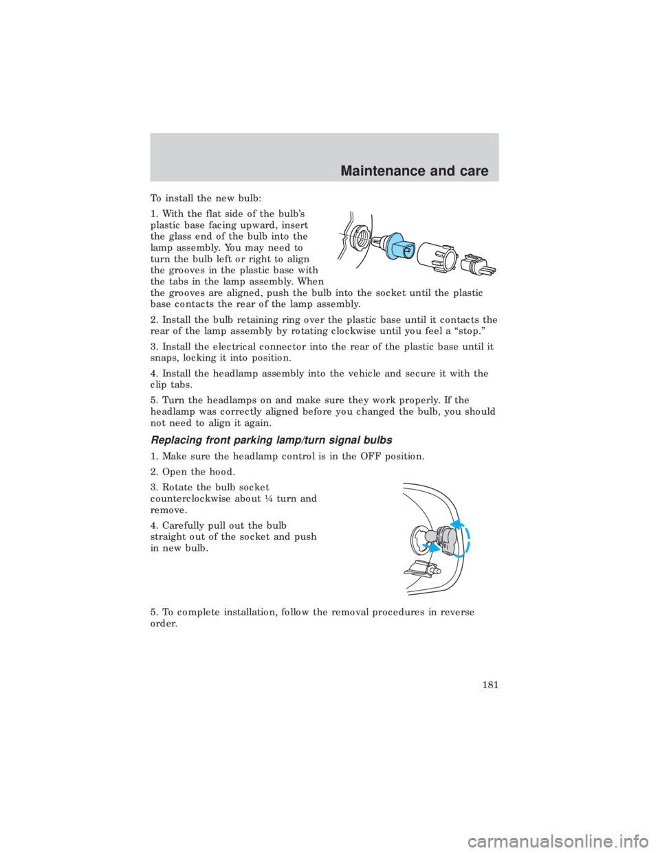
To install the new bulb:
1. With the flat side of the bulb's
plastic base facing upward, insert
the glass end of the bulb into the
lamp assembly. You may need to
turn the bulb left or right to align
the grooves in the plastic base with
the tabs in the lamp assembly. When
the grooves are aligned, push the bulb into the socket until the plastic
base contacts the rear of the lamp assembly.
2. Install the bulb retaining ring over the plastic base until it contacts the
rear of the lamp assembly by rotating clockwise until you feel a ªstop.º
3. Install the electrical connector into the rear of the plastic base until it
snaps, locking it into position.
4. Install the headlamp assembly into the vehicle and secure it with the
clip tabs.
5. Turn the headlamps on and make sure they work properly. If the
headlamp was correctly aligned before you changed the bulb, you should
not need to align it again.
Replacing front parking lamp/turn signal bulbs
1. Make sure the headlamp control is in the OFF position.
2. Open the hood.
3. Rotate the bulb socket
counterclockwise about ò turn and
remove.
4. Carefully pull out the bulb
straight out of the socket and push
in new bulb.
5. To complete installation, follow the removal procedures in reverse
order.
Maintenance and care
181