fuse box FORD E350 2009 Owners Manual
[x] Cancel search | Manufacturer: FORD, Model Year: 2009, Model line: E350, Model: FORD E350 2009Pages: 320, PDF Size: 2.24 MB
Page 63 of 320
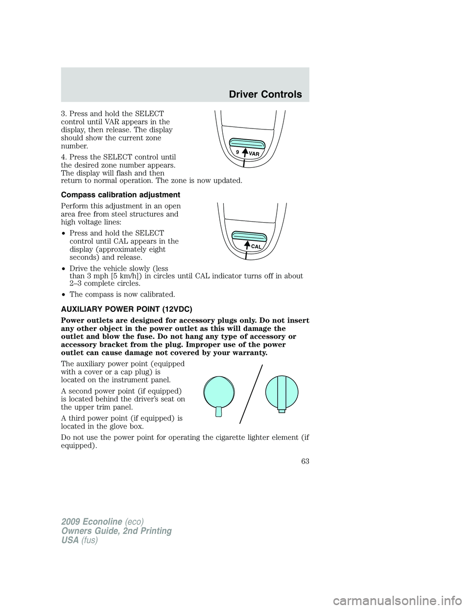
3. Press and hold the SELECT
control until VAR appears in the
display, then release. The display
should show the current zone
number.
4. Press the SELECT control until
the desired zone number appears.
The display will flash and then
return to normal operation. The zone is now updated.
Compass calibration adjustment
Perform this adjustment in an open
area free from steel structures and
high voltage lines:
•Press and hold the SELECT
control until CAL appears in the
display (approximately eight
seconds) and release.
•Drive the vehicle slowly (less
than 3 mph [5 km/h]) in circles until CAL indicator turns off in about
2–3 complete circles.
•The compass is now calibrated.
AUXILIARY POWER POINT (12VDC)
Power outlets are designed for accessory plugs only. Do not insert
any other object in the power outlet as this will damage the
outlet and blow the fuse. Do not hang any type of accessory or
accessory bracket from the plug. Improper use of the power
outlet can cause damage not covered by your warranty.
The auxiliary power point (equipped
with a cover or a cap plug) is
located on the instrument panel.
A second power point (if equipped)
is located behind the driver’s seat on
the upper trim panel.
A third power point (if equipped) is
located in the glove box.
Do not use the power point for operating the cigarette lighter element (if
equipped).
9 VAR
CAL
2009 Econoline(eco)
Owners Guide, 2nd Printing
USA(fus)
Driver Controls
63
Page 70 of 320
Turning off speed control
There are two ways to turn off the
speed control:
•Depress the brake pedal. This will
not erase your vehicle’s
previously set speed.
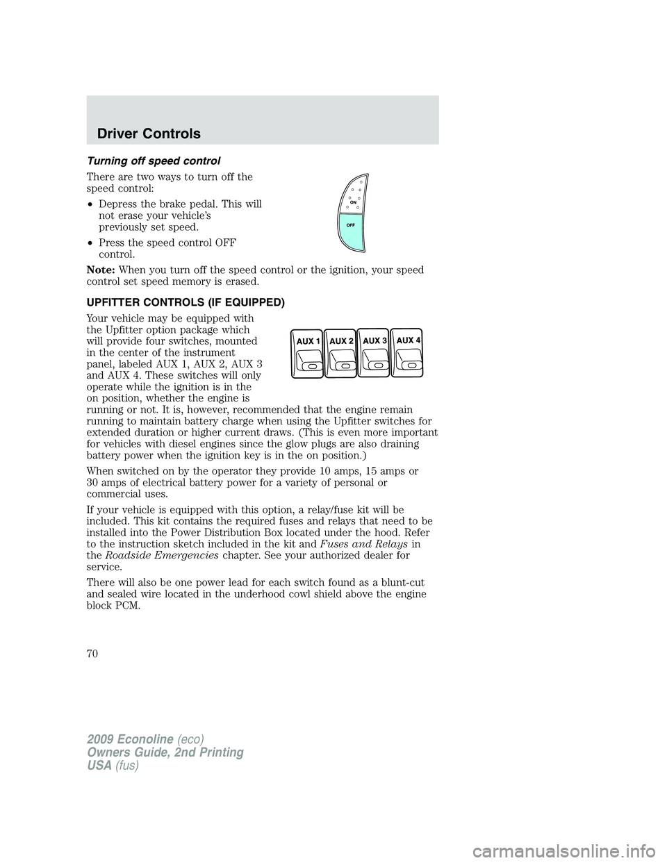
•Press the speed control OFF
control.
Note:When you turn off the speed control or the ignition, your speed
control set speed memory is erased.
UPFITTER CONTROLS (IF EQUIPPED)
Your vehicle may be equipped with
the Upfitter option package which
will provide four switches, mounted
in the center of the instrument
panel, labeled AUX 1, AUX 2, AUX 3
and AUX 4. These switches will only
operate while the ignition is in the
on position, whether the engine is
running or not. It is, however, recommended that the engine remain
running to maintain battery charge when using the Upfitter switches for
extended duration or higher current draws. (This is even more important
for vehicles with diesel engines since the glow plugs are also draining
battery power when the ignition key is in the on position.)
When switched on by the operator they provide 10 amps, 15 amps or
30 amps of electrical battery power for a variety of personal or
commercial uses.
If your vehicle is equipped with this option, a relay/fuse kit will be
included. This kit contains the required fuses and relays that need to be
installed into the Power Distribution Box located under the hood. Refer
to the instruction sketch included in the kit andFuses and Relaysin
theRoadside Emergencieschapter. See your authorized dealer for
service.
There will also be one power lead for each switch found as a blunt-cut
and sealed wire located in the underhood cowl shield above the engine
block PCM.
2009 Econoline(eco)
Owners Guide, 2nd Printing
USA(fus)
Driver Controls
70
Page 231 of 320
Fuse/Relay
LocationFuse Amp
RatingProtected Circuits
35 10A Reverse park aid, Rear video
camera, Cutaway run/start
36 5A PATS RF module
37 10A Climate control, Stripped chassis
IP #1 run/start
38 20A Not used (spare)
39 20A Radio, Navigation
40 20A Amplifier
41 15A Radio, Switch illumination,
Reverse camera mirror
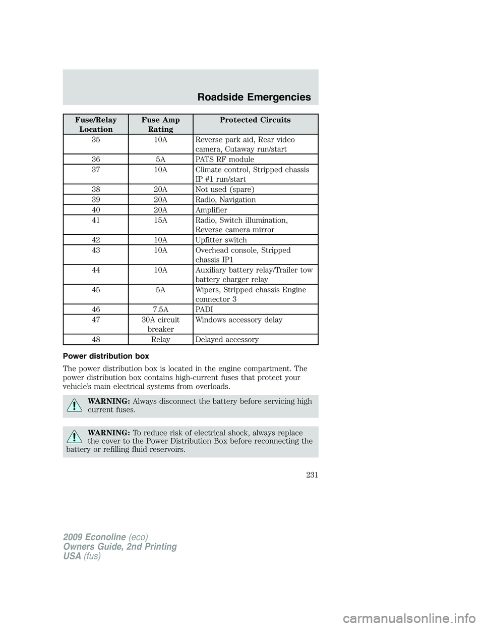
42 10A Upfitter switch
43 10A Overhead console, Stripped
chassis IP1
44 10A Auxiliary battery relay/Trailer tow
battery charger relay
45 5A Wipers, Stripped chassis Engine
connector 3
46 7.5A PADI
47 30A circuit
breakerWindows accessory delay
48 Relay Delayed accessory
Power distribution box
The power distribution box is located in the engine compartment. The
power distribution box contains high-current fuses that protect your
vehicle’s main electrical systems from overloads.
WARNING:Always disconnect the battery before servicing high
current fuses.
WARNING:To reduce risk of electrical shock, always replace
the cover to the Power Distribution Box before reconnecting the
battery or refilling fluid reservoirs.
2009 Econoline(eco)
Owners Guide, 2nd Printing
USA(fus)
Roadside Emergencies
231
Page 235 of 320
Fuse/Relay
LocationFuse Amp
RatingProtected Circuits
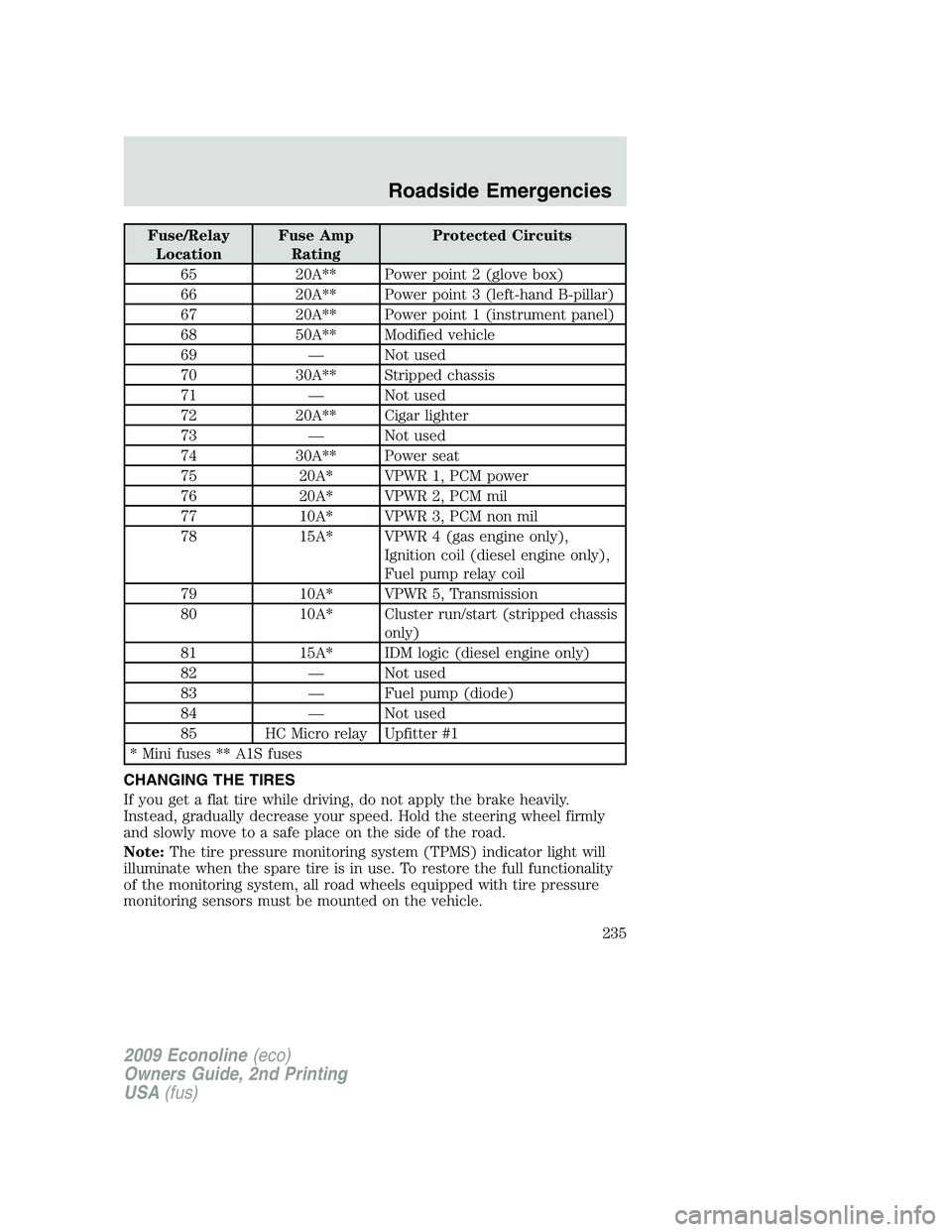
65 20A** Power point 2 (glove box)
66 20A** Power point 3 (left-hand B-pillar)
67 20A** Power point 1 (instrument panel)
68 50A** Modified vehicle
69 — Not used
70 30A** Stripped chassis
71 — Not used
72 20A** Cigar lighter
73 — Not used
74 30A** Power seat
75 20A* VPWR 1, PCM power
76 20A* VPWR 2, PCM mil
77 10A* VPWR 3, PCM non mil
78 15A* VPWR 4 (gas engine only),
Ignition coil (diesel engine only),
Fuel pump relay coil
79 10A* VPWR 5, Transmission
80 10A* Cluster run/start (stripped chassis
only)
81 15A* IDM logic (diesel engine only)
82 — Not used
83 — Fuel pump (diode)
84 — Not used
85 HC Micro relay Upfitter #1
* Mini fuses ** A1S fuses
CHANGING THE TIRES
If you get a flat tire while driving, do not apply the brake heavily.
Instead, gradually decrease your speed. Hold the steering wheel firmly
and slowly move to a safe place on the side of the road.
Note:The tire pressure monitoring system (TPMS) indicator light will
illuminate when the spare tire is in use. To restore the full functionality
of the monitoring system, all road wheels equipped with tire pressure
monitoring sensors must be mounted on the vehicle.
2009 Econoline(eco)
Owners Guide, 2nd Printing
USA(fus)
Roadside Emergencies
235
Page 318 of 320
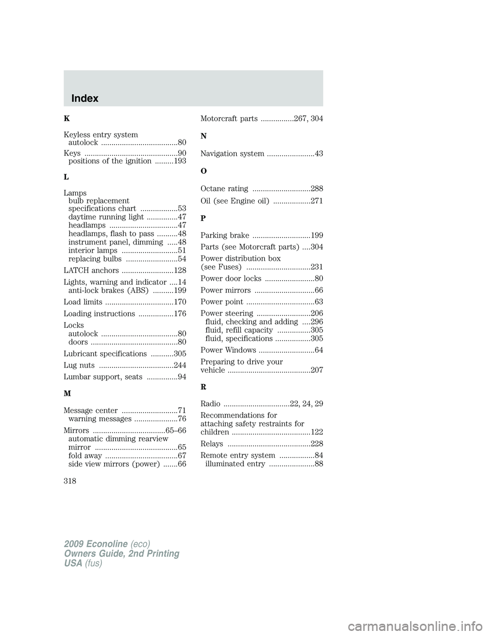
K
Keyless entry system
autolock .....................................80
Keys .............................................90
positions of the ignition .........193
L
Lamps
bulb replacement
specifications chart ..................53
daytime running light ...............47
headlamps .................................47
headlamps, flash to pass ..........48
instrument panel, dimming .....48
interior lamps ...........................51
replacing bulbs .........................54
LATCH anchors .........................128
Lights, warning and indicator ....14
anti-lock brakes (ABS) ..........199
Load limits .................................170
Loading instructions .................176
Locks
autolock .....................................80
doors ..........................................80
Lubricant specifications ...........305
Lug nuts ....................................244
Lumbar support, seats ...............94
M
Message center ...........................71
warning messages .....................76
Mirrors ...................................65–66
automatic dimming rearview
mirror ........................................65
fold away ...................................67
side view mirrors (power) .......66Motorcraft parts ................267, 304
N
Navigation system .......................43
O
Octane rating ............................288
Oil (see Engine oil) ..................271
P
Parking brake ............................199
Parts (see Motorcraft parts) ....304
Power distribution box
(see Fuses) ...............................231
Power door locks ........................80
Power mirrors .............................66
Power point .................................63
Power steering ..........................206
fluid, checking and adding ....296
fluid, refill capacity ................305
fluid, specifications .................305
Power Windows ...........................64
Preparing to drive your
vehicle ........................................207
R
Radio ................................22, 24, 29
Recommendations for
attaching safety restraints for
children ......................................122
Relays ........................................228
Remote entry system .................84
illuminated entry ......................88
2009 Econoline(eco)
Owners Guide, 2nd Printing
USA(fus)
Index
318