FORD ECONOLINE 2009 Owners Manual
Manufacturer: FORD, Model Year: 2009, Model line: ECONOLINE, Model: FORD ECONOLINE 2009Pages: 320, PDF Size: 2.52 MB
Page 241 of 320
WARNING:To lessen the risk of personal injury, do not put any
part of your body under the vehicle while changing a tire. Do not
start the engine when your vehicle is on the jack. The jack is only
meant for changing the tire.
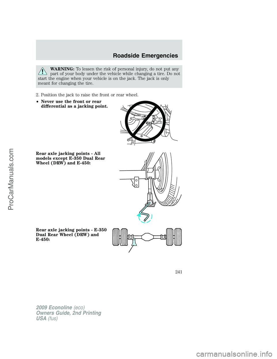
2. Position the jack to raise the front or rear wheel.
•Never use the front or rear
differential as a jacking point.
Rear axle jacking points - All
models except E-350 Dual Rear
Wheel (DRW) and E-450:
Rear axle jacking points - E-350
Dual Rear Wheel (DRW) and
E-450:
2009 Econoline(eco)
Owners Guide, 2nd Printing
USA(fus)
Roadside Emergencies
241
ProCarManuals.com
Page 242 of 320
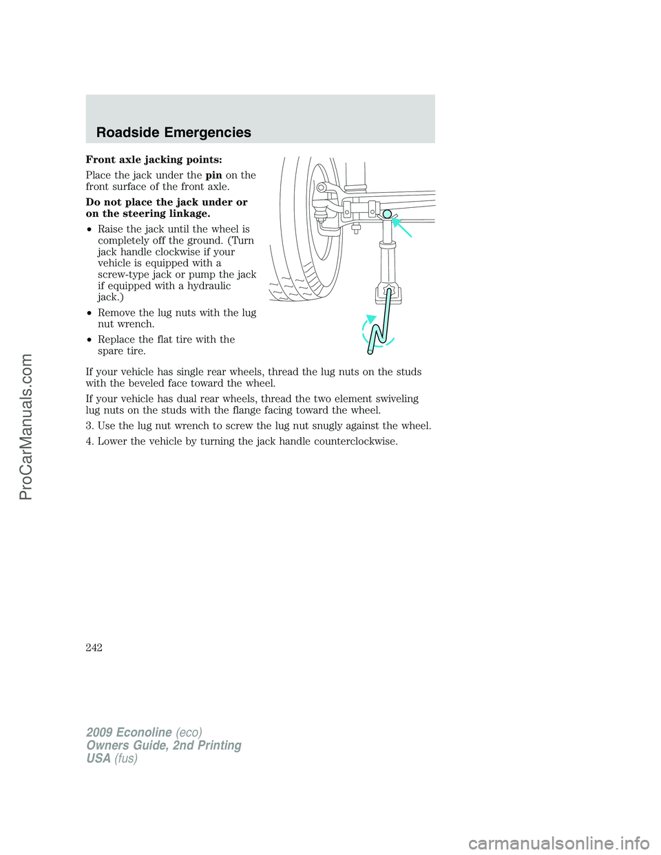
Front axle jacking points:
Place the jack under thepinon the
front surface of the front axle.
Do not place the jack under or
on the steering linkage.
•Raise the jack until the wheel is
completely off the ground. (Turn
jack handle clockwise if your
vehicle is equipped with a
screw-type jack or pump the jack
if equipped with a hydraulic
jack.)
•Remove the lug nuts with the lug
nut wrench.
•Replace the flat tire with the
spare tire.
If your vehicle has single rear wheels, thread the lug nuts on the studs
with the beveled face toward the wheel.
If your vehicle has dual rear wheels, thread the two element swiveling
lug nuts on the studs with the flange facing toward the wheel.
3. Use the lug nut wrench to screw the lug nut snugly against the wheel.
4. Lower the vehicle by turning the jack handle counterclockwise.
2009 Econoline(eco)
Owners Guide, 2nd Printing
USA(fus)
Roadside Emergencies
242
ProCarManuals.com
Page 243 of 320
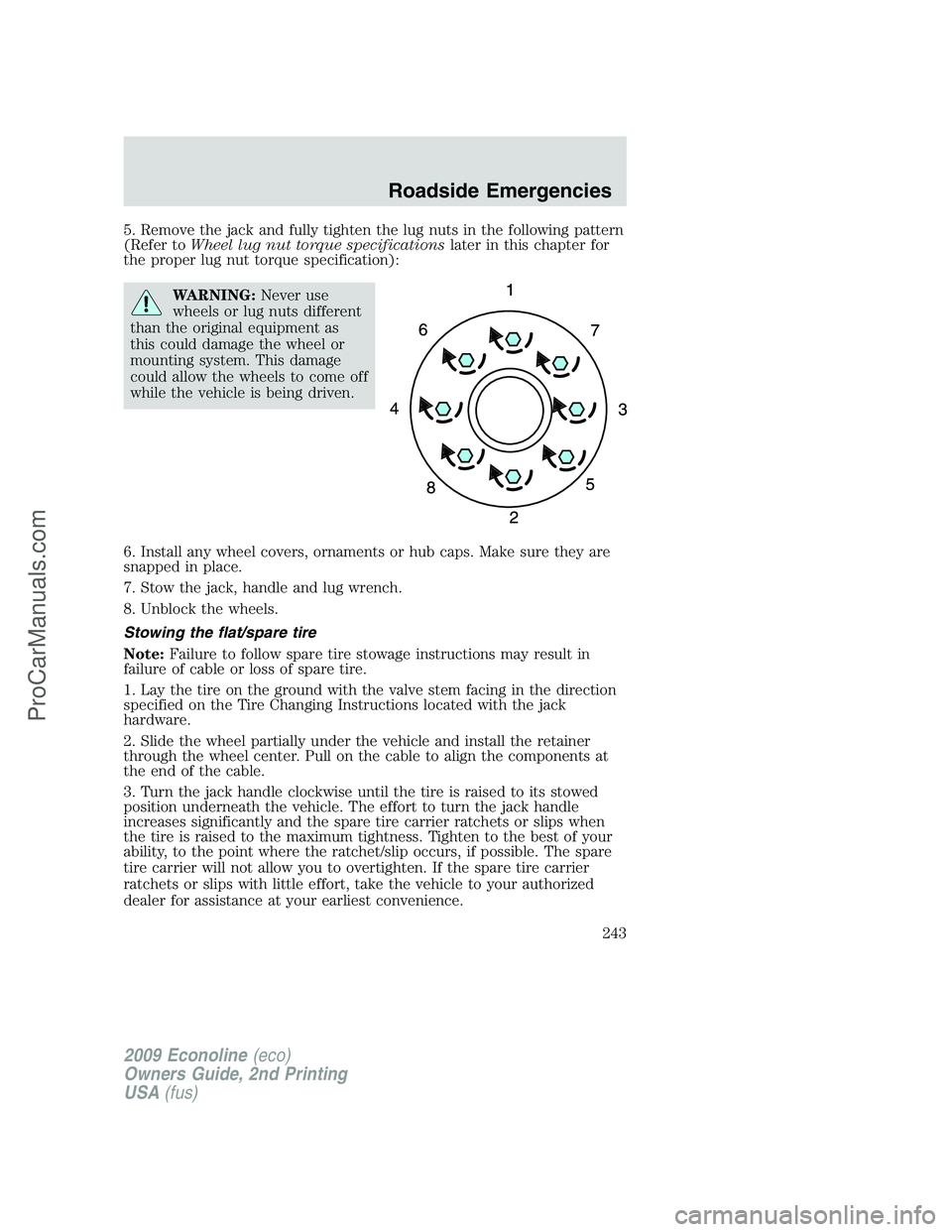
5. Remove the jack and fully tighten the lug nuts in the following pattern
(Refer toWheel lug nut torque specificationslater in this chapter for
the proper lug nut torque specification):
WARNING:Never use
wheels or lug nuts different
than the original equipment as
this could damage the wheel or
mounting system. This damage
could allow the wheels to come off
while the vehicle is being driven.
6. Install any wheel covers, ornaments or hub caps. Make sure they are
snapped in place.
7. Stow the jack, handle and lug wrench.
8. Unblock the wheels.
Stowing the flat/spare tire
Note:Failure to follow spare tire stowage instructions may result in
failure of cable or loss of spare tire.
1. Lay the tire on the ground with the valve stem facing in the direction
specified on the Tire Changing Instructions located with the jack
hardware.
2. Slide the wheel partially under the vehicle and install the retainer
through the wheel center. Pull on the cable to align the components at
the end of the cable.
3. Turn the jack handle clockwise until the tire is raised to its stowed
position underneath the vehicle. The effort to turn the jack handle
increases significantly and the spare tire carrier ratchets or slips when
the tire is raised to the maximum tightness. Tighten to the best of your
ability, to the point where the ratchet/slip occurs, if possible. The spare
tire carrier will not allow you to overtighten. If the spare tire carrier
ratchets or slips with little effort, take the vehicle to your authorized
dealer for assistance at your earliest convenience.
2009 Econoline(eco)
Owners Guide, 2nd Printing
USA(fus)
Roadside Emergencies
243
ProCarManuals.com
Page 244 of 320
4. Check that the tire lies flat against the frame and is properly
tightened. Try to push or pull, then turn the tire to be sure it will not
move. Loosen and retighten, if necessary. Failure to properly stow the
spare tire may result in failure of the winch cable and loss of the tire.
5. Repeat this tightness check procedure when servicing the spare tire
pressure (every six months, as per yourscheduled maintenance
information),or at any time that the spare tire is disturbed through
service of other components.
6. If removed, install the spare tire lock (if equipped) into the bumper
drive tube with the spare tire lock key (if equipped) and jack handle.
WHEEL LUG NUT TORQUE SPECIFICATIONS
On vehicles equipped with single rear wheels, retighten the lug nuts to
the specified torque at 100 miles (160 km) after any wheel disturbance
(tire rotation, changing a flat tire, wheel removal, etc.).
On vehicles equipped with dual rear wheels, retighten the wheel lug nuts
to the specified torque at 100 miles (160 km), and again at 500 miles
(800 km) of new vehicle operation and after any wheel disturbance (tire
rotation, changing a flat tire, wheel removal, etc.).
Bolt size and wheel
lug nut typeWheel lug nut torque*
lb.ft. N•m
9/16 x 18 conical lug
nut150 200
9/16 x 18 two-piece
lug nut140 190
* Torque specifications are for nut and bolt threads free of dirt and
rust. Use only Ford recommended replacement fasteners.
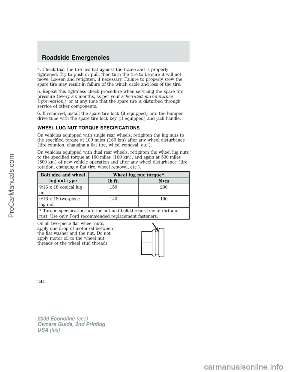
On all two-piece flat wheel nuts,
apply one drop of motor oil between
the flat washer and the nut. Do not
apply motor oil to the wheel nut
threads or the wheel stud threads.
2009 Econoline(eco)
Owners Guide, 2nd Printing
USA(fus)
Roadside Emergencies
244
ProCarManuals.com
Page 245 of 320
WARNING:When a wheel is installed, always remove any
corrosion, dirt or foreign materials present on the mounting
surfaces of the wheel or the surface of the wheel hub, brake drum or
brake disc that contacts the wheel. Ensure that any fasteners that
attach the rotor to the hub are secured so they do not interfere with
the mounting surfaces of the wheel. Installing wheels without correct
metal-to-metal contact at the wheel mounting surfaces can cause the
wheel nuts to loosen and the wheel to come off while the vehicle is in
motion, resulting in loss of control.
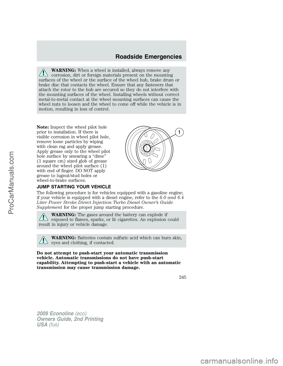
Note:Inspect the wheel pilot hole
prior to installation. If there is
visible corrosion in wheel pilot hole,
remove loose particles by wiping
with clean rag and apply grease.
Apply grease only to the wheel pilot
hole surface by smearing a “dime”
(1 square cm) sized glob of grease
around the wheel pilot surface (1)
with end of finger. DO NOT apply
grease to lugnut/stud holes or
wheel-to-brake surfaces.
JUMP STARTING YOUR VEHICLE
The following procedure is for vehicles equipped with a gasoline engine;
if your vehicle is equipped with a diesel engine, refer to the6.0 and 6.4
Liter Power Stroke Direct Injection Turbo Diesel Owner’s Guide
Supplementfor the proper jump starting procedure.
WARNING:The gases around the battery can explode if
exposed to flames, sparks, or lit cigarettes. An explosion could
result in injury or vehicle damage.
WARNING:Batteries contain sulfuric acid which can burn skin,
eyes and clothing, if contacted.
Do not attempt to push-start your automatic transmission
vehicle. Automatic transmissions do not have push-start
capability. Attempting to push-start a vehicle with an automatic
transmission may cause transmission damage.
2009 Econoline(eco)
Owners Guide, 2nd Printing
USA(fus)
Roadside Emergencies
245
ProCarManuals.com
Page 246 of 320
Preparing your vehicle
When the battery is disconnected or a new battery is installed, the
automatic transmission must relearn its shift strategy. As a result, the
transmission may have firm and/or soft shifts. This operation is
considered normal and will not affect function or durability of the
transmission. Over time, the adaptive learning process will fully update
transmission operation.
1.Use only a 12–volt supply to start your vehicle.
2. Do not disconnect the battery of the disabled vehicle as this could
damage the vehicle’s electrical system.
3. Park the booster vehicle close to the hood of the disabled vehicle
making sure the two vehiclesdo nottouch. Set the parking brake on
both vehicles and stay clear of the engine cooling fan and other moving
parts.
4. Check all battery terminals and remove any excessive corrosion before
you attach the battery cables. Ensure that vent caps are tight and level.
5. Turn the heater fan on in both vehicles to protect from any electrical
surges. Turn all other accessories off.
Connecting the jumper cables
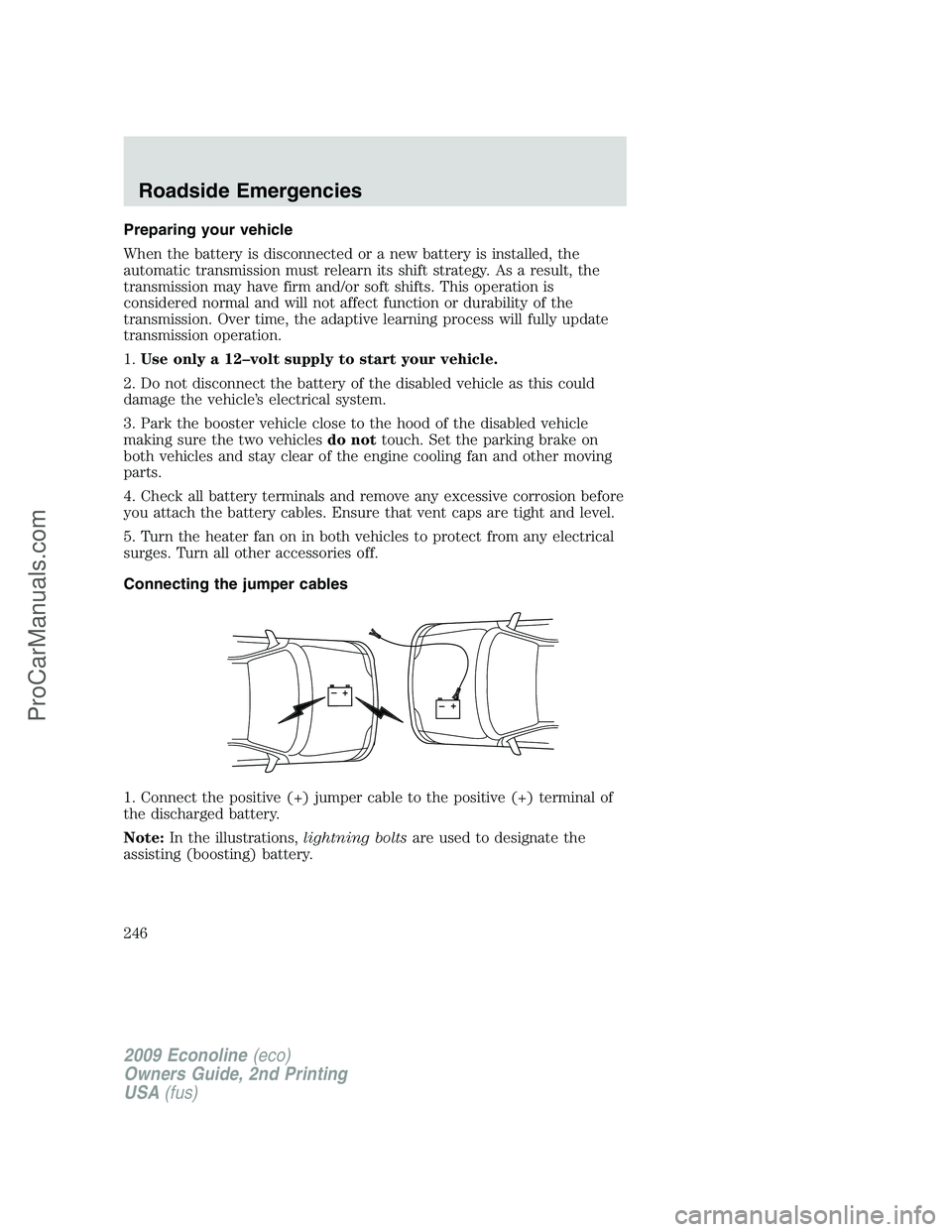
1. Connect the positive (+) jumper cable to the positive (+) terminal of
the discharged battery.
Note:In the illustrations,lightning boltsare used to designate the
assisting (boosting) battery.
+–+–
2009 Econoline(eco)
Owners Guide, 2nd Printing
USA(fus)
Roadside Emergencies
246
ProCarManuals.com
Page 247 of 320
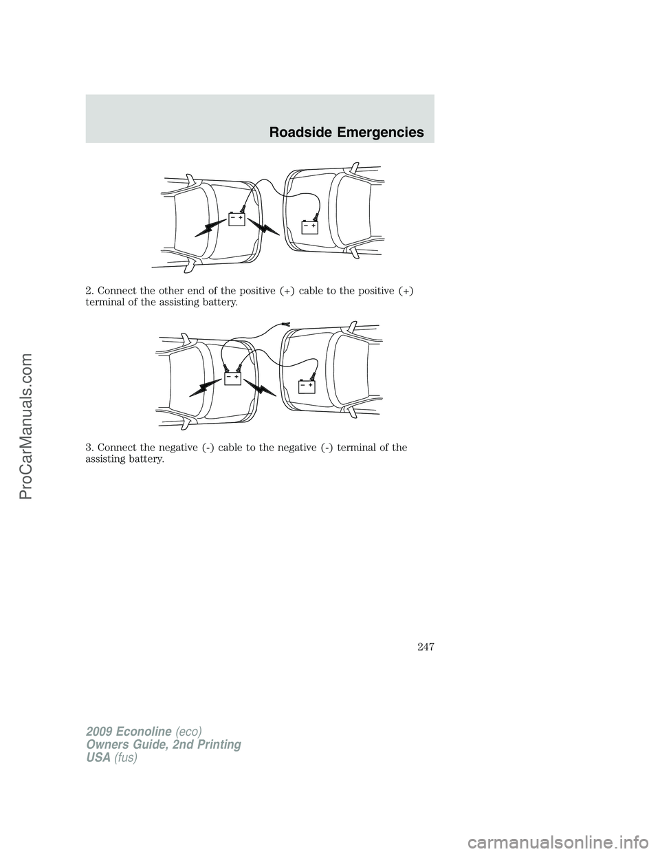
2. Connect the other end of the positive (+) cable to the positive (+)
terminal of the assisting battery.
3. Connect the negative (-) cable to the negative (-) terminal of the
assisting battery.
+–+–
+–+–
2009 Econoline(eco)
Owners Guide, 2nd Printing
USA(fus)
Roadside Emergencies
247
ProCarManuals.com
Page 248 of 320
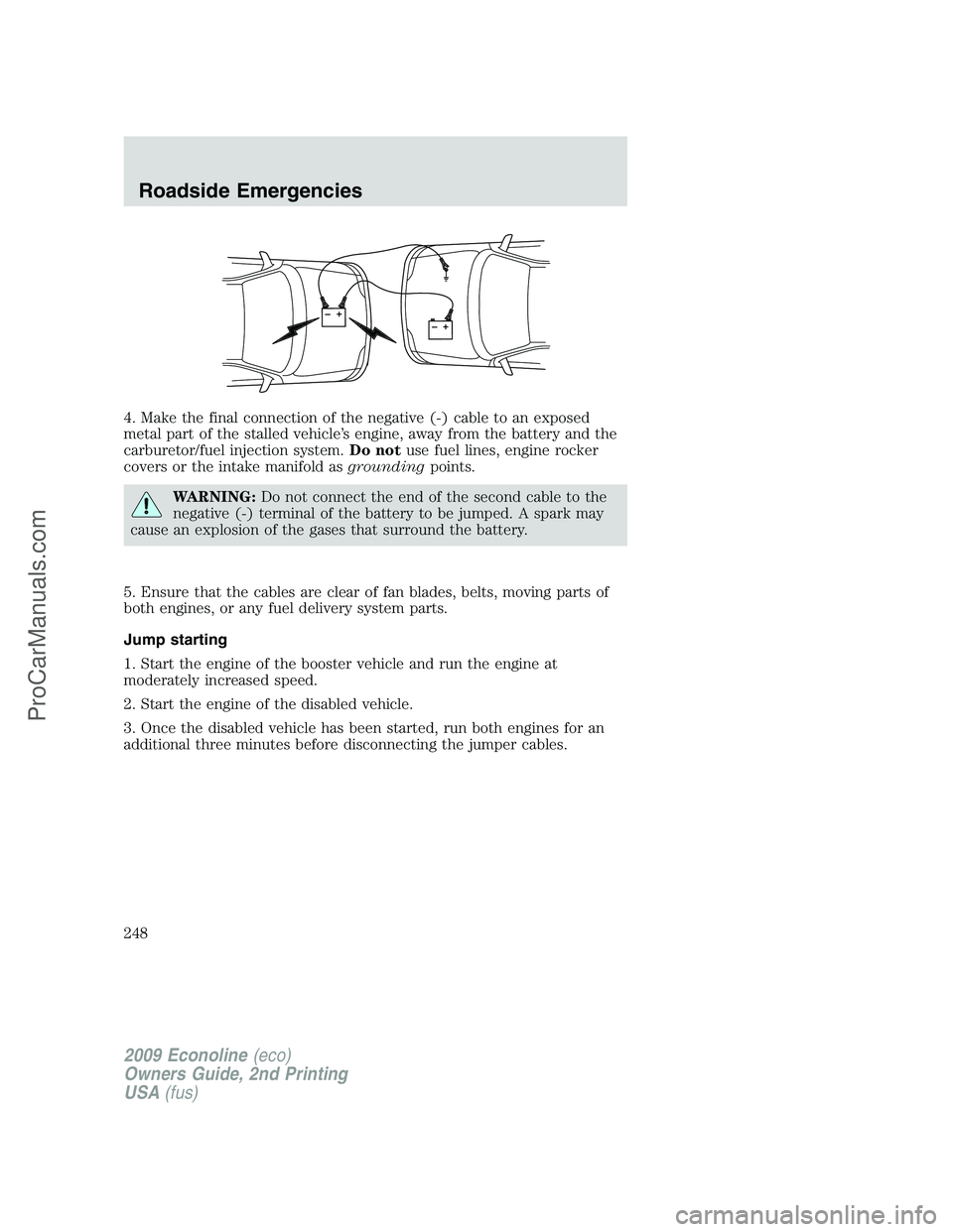
4. Make the final connection of the negative (-) cable to an exposed
metal part of the stalled vehicle’s engine, away from the battery and the
carburetor/fuel injection system.Do notuse fuel lines, engine rocker
covers or the intake manifold asgroundingpoints.
WARNING:Do not connect the end of the second cable to the
negative (-) terminal of the battery to be jumped. A spark may
cause an explosion of the gases that surround the battery.
5. Ensure that the cables are clear of fan blades, belts, moving parts of
both engines, or any fuel delivery system parts.
Jump starting
1. Start the engine of the booster vehicle and run the engine at
moderately increased speed.
2. Start the engine of the disabled vehicle.
3. Once the disabled vehicle has been started, run both engines for an
additional three minutes before disconnecting the jumper cables.
+–+–
2009 Econoline(eco)
Owners Guide, 2nd Printing
USA(fus)
Roadside Emergencies
248
ProCarManuals.com
Page 249 of 320
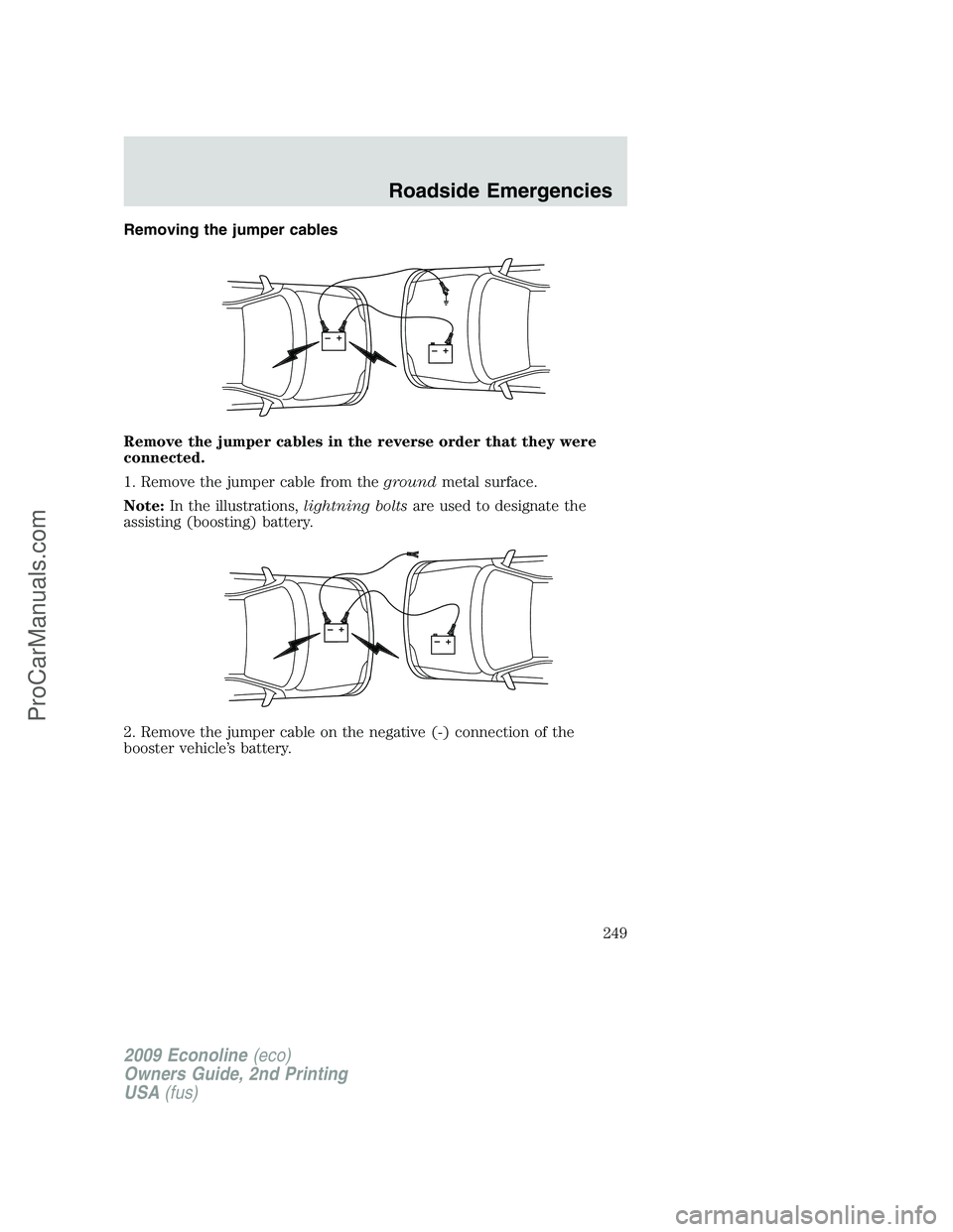
Removing the jumper cables
Remove the jumper cables in the reverse order that they were
connected.
1. Remove the jumper cable from thegroundmetal surface.
Note:In the illustrations,lightning boltsare used to designate the
assisting (boosting) battery.
2. Remove the jumper cable on the negative (-) connection of the
booster vehicle’s battery.
+–+–
+–+–
2009 Econoline(eco)
Owners Guide, 2nd Printing
USA(fus)
Roadside Emergencies
249
ProCarManuals.com
Page 250 of 320
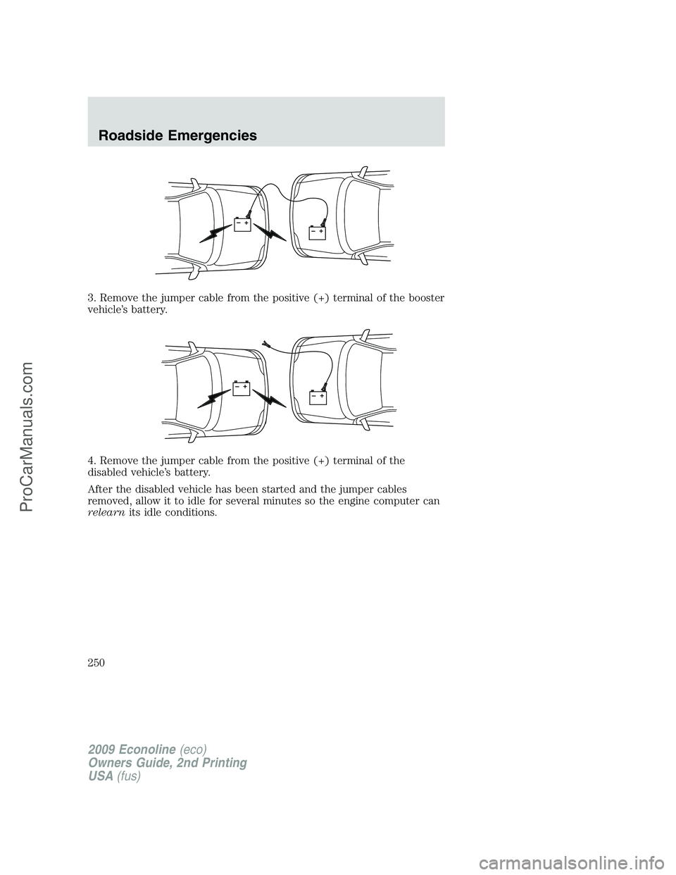
3. Remove the jumper cable from the positive (+) terminal of the booster
vehicle’s battery.
4. Remove the jumper cable from the positive (+) terminal of the
disabled vehicle’s battery.
After the disabled vehicle has been started and the jumper cables
removed, allow it to idle for several minutes so the engine computer can
relearnits idle conditions.
+–+–
+–+–
2009 Econoline(eco)
Owners Guide, 2nd Printing
USA(fus)
Roadside Emergencies
250
ProCarManuals.com