tow FORD ECONOLINE 2009 Owner's Manual
[x] Cancel search | Manufacturer: FORD, Model Year: 2009, Model line: ECONOLINE, Model: FORD ECONOLINE 2009Pages: 320, PDF Size: 2.52 MB
Page 163 of 320
Low Tire
Pressure
Warning
LightPossible cause Customer Action Required
Solid
Warning
LightTire(s)
under-inflated1. Check your tire pressure to ensure tires
are properly inflated; refer toInflating
your tiresin this chapter.
2. After inflating your tires to the
manufacturer’s recommended inflation
pressure as shown on the Tire Label
(located on the edge of driver’s door or
the B-Pillar), the vehicle must be driven
for at least two minutes over 20 mph
(32 km/h) before the light will turn OFF.
Spare tire in use Your temporary spare tire is in use. Repair
the damaged road wheel/tire and reinstall
it on the vehicle to restore system
functionality. For a description on how the
system functions, refer toWhen your
temporary spare tire is installedin this
section.
TPMS
malfunctionIf your tires are properly inflated and your
spare tire is not in use and the light
remains ON, contact your authorized
dealer as soon as possible.
Tire rotation
without sensor
trainingOn vehicles with different front and rear
tire pressures, the TPMS system must be
retrained following every tire rotation.
Refer toTire rotationin this chapter.
Flashing
Warning
LightSpare tire in use Your temporary spare tire is in use. Repair
the damaged road wheel and re-mount it
on the vehicle to restore system
functionality. For a description of how the
system functions under these conditions,
refer toWhen your temporary spare tire
is installedin this section.
TPMS
malfunctionIf your tires are properly inflated and your
spare tire is not in use and the TPMS
warning light still flashes, contact your
authorized dealer as soon as possible.
2009 Econoline(eco)
Owners Guide, 2nd Printing
USA(fus)
Tires, Wheels and Loading
163
ProCarManuals.com
Page 168 of 320
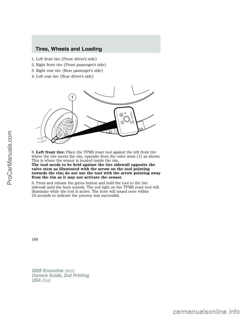
1. Left front tire (Front driver’s side)
2. Right front tire (Front passenger’s side)
3. Right rear tire (Rear passenger’s side)
4. Left rear tire (Rear driver’s side)
8.Left front tire:Place the TPMS reset tool against the left front tire
where the tire meets the rim, opposite from the valve stem (1) as shown.
This is where the sensor is located inside the rim.
The tool needs to be held against the tire sidewall opposite the
valve stem as illustrated with the arrow on the tool pointing
towards the rim; do not use the tool with the arrow pointing away
from the rim as it may not activate the sensor.
9. Press and release the green button and hold the tool to the tire
sidewall until the horn sounds. The red light on the TPMS reset tool will
illuminate while the tool is active. The horn will sound once within
10 seconds to indicate the process was successful.
2009 Econoline(eco)
Owners Guide, 2nd Printing
USA(fus)
Tires, Wheels and Loading
168
ProCarManuals.com
Page 172 of 320
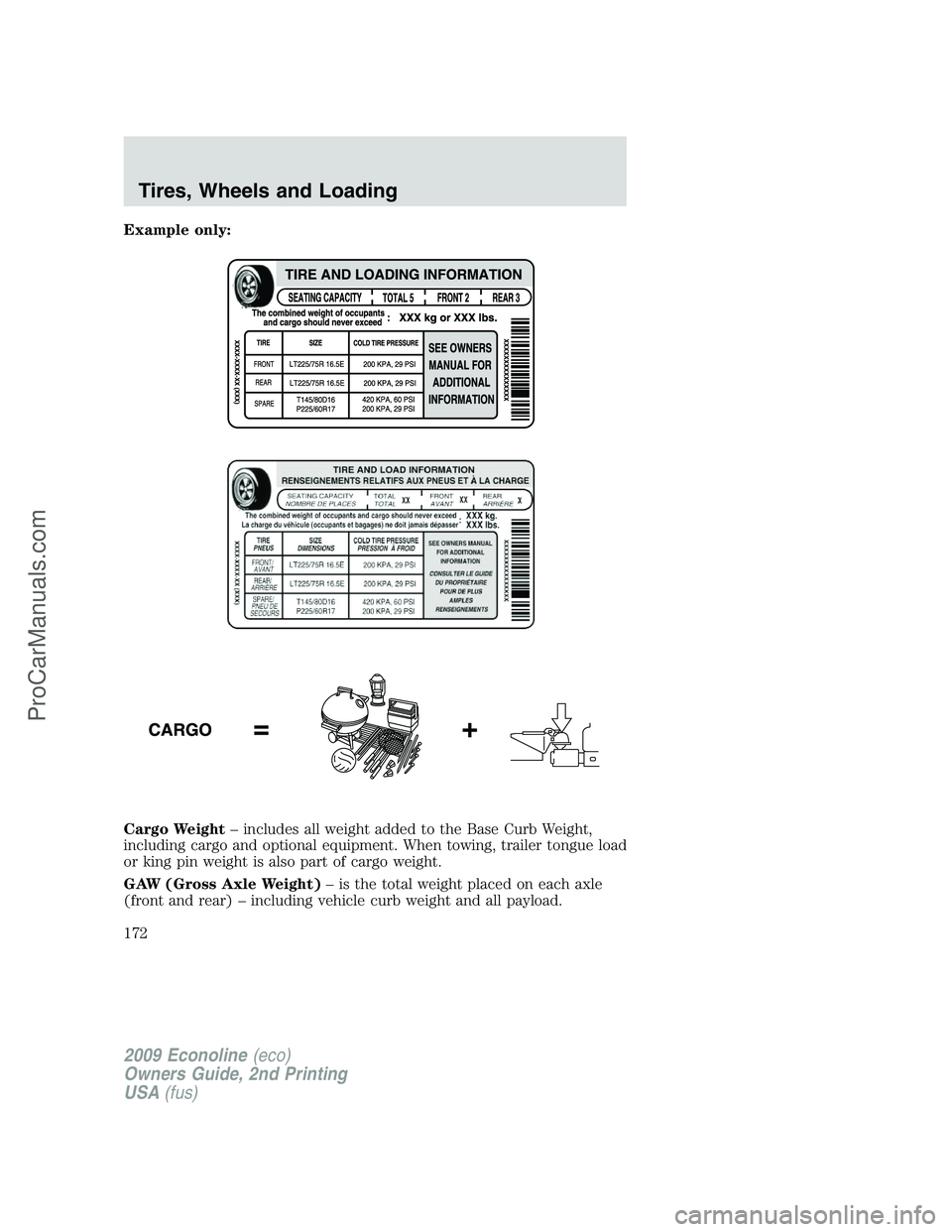
Example only:
Cargo Weight– includes all weight added to the Base Curb Weight,
including cargo and optional equipment. When towing, trailer tongue load
or king pin weight is also part of cargo weight.
GAW (Gross Axle Weight)– is the total weight placed on each axle
(front and rear) – including vehicle curb weight and all payload.
2009 Econoline(eco)
Owners Guide, 2nd Printing
USA(fus)
Tires, Wheels and Loading
172
ProCarManuals.com
Page 173 of 320
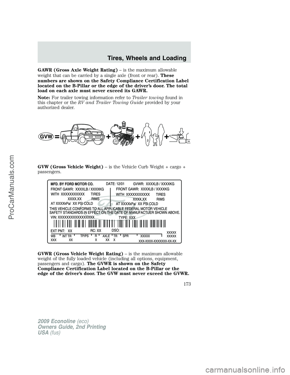
GAWR (Gross Axle Weight Rating)– is the maximum allowable
weight that can be carried by a single axle (front or rear).These
numbers are shown on the Safety Compliance Certification Label
located on the B-Pillar or the edge of the driver’s door. The total
load on each axle must never exceed its GAWR.
Note:For trailer towing information refer toTrailer towingfound in
this chapter or theRV and Trailer Towing Guideprovided by your
authorized dealer.
GVW (Gross Vehicle Weight)– is the Vehicle Curb Weight + cargo +
passengers.
GVWR (Gross Vehicle Weight Rating)– is the maximum allowable
weight of the fully loaded vehicle (including all options, equipment,
passengers and cargo).The GVWR is shown on the Safety
Compliance Certification Label located on the B-Pillar or the
edge of the driver’s door. The GVW must never exceed the GVWR.
2009 Econoline(eco)
Owners Guide, 2nd Printing
USA(fus)
Tires, Wheels and Loading
173
ProCarManuals.com
Page 174 of 320
WARNING:Exceeding the Safety Compliance Certification Label
vehicle weight rating limits could result in substandard vehicle
handling or performance, engine, transmission and/or structural
damage, serious damage to the vehicle, loss of control and personal
injury.
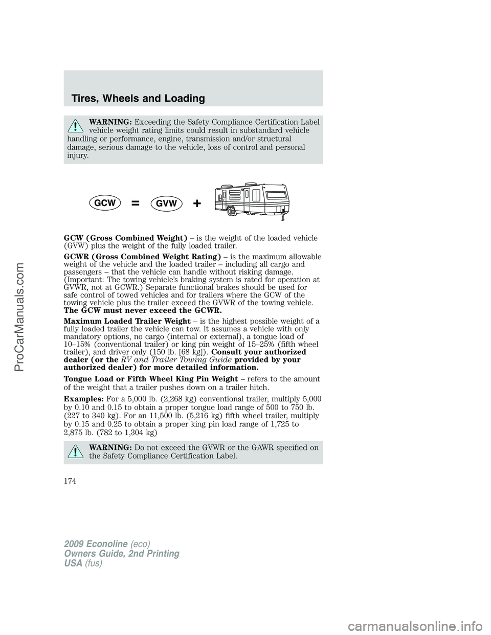
GCW (Gross Combined Weight)– is the weight of the loaded vehicle
(GVW) plus the weight of the fully loaded trailer.
GCWR (Gross Combined Weight Rating)– is the maximum allowable
weight of the vehicle and the loaded trailer – including all cargo and
passengers – that the vehicle can handle without risking damage.
(Important: The towing vehicle’s braking system is rated for operation at
GVWR, not at GCWR.) Separate functional brakes should be used for
safe control of towed vehicles and for trailers where the GCW of the
towing vehicle plus the trailer exceed the GVWR of the towing vehicle.
The GCW must never exceed the GCWR.
Maximum Loaded Trailer Weight– is the highest possible weight of a
fully loaded trailer the vehicle can tow. It assumes a vehicle with only
mandatory options, no cargo (internal or external), a tongue load of
10–15% (conventional trailer) or king pin weight of 15–25% (fifth wheel
trailer), and driver only (150 lb. [68 kg]).Consult your authorized
dealer (or theRV and Trailer Towing Guideprovided by your
authorized dealer) for more detailed information.
Tongue Load or Fifth Wheel King Pin Weight– refers to the amount
of the weight that a trailer pushes down on a trailer hitch.
Examples:For a 5,000 lb. (2,268 kg) conventional trailer, multiply 5,000
by 0.10 and 0.15 to obtain a proper tongue load range of 500 to 750 lb.
(227 to 340 kg). For an 11,500 lb. (5,216 kg) fifth wheel trailer, multiply
by 0.15 and 0.25 to obtain a proper king pin load range of 1,725 to
2,875 lb. (782 to 1,304 kg)
WARNING:Do not exceed the GVWR or the GAWR specified on
the Safety Compliance Certification Label.
2009 Econoline(eco)
Owners Guide, 2nd Printing
USA(fus)
Tires, Wheels and Loading
174
ProCarManuals.com
Page 175 of 320
WARNING:Do not use replacement tires with lower load
carrying capacities than the original tires because they may
lower the vehicle’s GVWR and GAWR limitations. Replacement tires
with a higher limit than the original tires do not increase the GVWR
and GAWR limitations.
WARNING:Exceeding any vehicle weight rating limitation could
result in serious damage to the vehicle and/or personal injury.
Steps for determining the correct load limit:
1. Locate the statement “The combined weight of occupants and cargo
should never exceed XXX kg or XXX lb.” on your vehicle’s placard.
2. Determine the combined weight of the driver and passengers that will
be riding in your vehicle.
3. Subtract the combined weight of the driver and passengers from XXX
kg or XXX lb.
4. The resulting figure equals the available amount of cargo and luggage
load capacity. For example, if the “XXX” amount equals 1,400 lb. and
there will be five 150 lb. passengers in your vehicle, the amount of
available cargo and luggage load capacity is 650 lb. (1400-750 (5 x 150)
= 650 lb.). In metric units (635-340 (5 x 68) = 295 kg.)
5. Determine the combined weight of luggage and cargo being loaded on
the vehicle. That weight may not safely exceed the available cargo and
luggage load capacity calculated in Step 4.
6. If your vehicle will be towing a trailer, load from your trailer will be
transferred to your vehicle. Consult this manual to determine how this
reduces the available cargo and luggage load capacity of your vehicle.
The following gives you a few examples on how to calculate the available
amount of cargo and luggage load capacity:
•Another example for your vehicle with 1,400 lb. (635 kg) of cargo and
luggage capacity. You decide to go golfing. Is there enough load
capacity to carry you, 4 of your friends and all the golf bags? You and
four friends average 220 lb. (99 kg) each and the golf bags weigh
approximately 30 lb. (13.5 kg) each. The calculation would be: 1400 -
(5 x 220) - (5 x 30) = 1400 - 1100 - 150 = 150 lb. Yes, you have
enough load capacity in your vehicle to transport four friends and
your golf bags. In metric units, the calculation would be: 635 kg - (5 x
99 kg) - (5 x 13.5 kg) = 635 - 495 - 67.5 = 72.5 kg.
2009 Econoline(eco)
Owners Guide, 2nd Printing
USA(fus)
Tires, Wheels and Loading
175
ProCarManuals.com
Page 177 of 320
TRAILER TOWING
Refer to6.0 and 6.4 Liter Power Stroke Direct Injection Turbo Diesel
Owner’s Guide Supplementfor Diesel engine towing information.
Your vehicle may tow a class I, II or III trailer, provided the maximum
trailer weight is less than or equal to the maximum trailer weight listed
for your engine and rear axle ratio on the following charts.
GCWR (Gross Combined Weight Rating)/Trailer Weights
EngineRear
axle
ratioMaximum
GCWR - lb.
(kg)Maximum
Loaded
Trailer Weight
- lb. (kg)Maximum
frontal area of
trailer - ft
2
(m2)
E-150 Regular/RV Van (8520 GVWR)
4.6L 3.7311500
(5216)6000 (2722) 60 (5.52)
4.6L 4.1012000
(5443)6500 (2948) 60 (5.52)
E-150 Regular Wagon (7/8 Passenger) (8520 GVWR)
4.6L 3.7311500
(5216)5500 (2495) 60 (5.52)
4.6L 4.1012000
(5443)6000 (2722) 60 (5.52)
E-150 Regular/RV Van (8600 GVWR)
5.4L 3.7313000
(5897)7400 (3357) 60 (5.52)
5.4L 4.1013000
(5897)7400 (3357) 60 (5.52)
E-150 Extended Van (8600 GVWR)
4.6L 3.7311500
(5216)5800 (2631) 60 (5.52)
4.6L 4.1012000
(5443)6300 (2858) 60 (5.52)
2009 Econoline(eco)
Owners Guide, 2nd Printing
USA(fus)
Tires, Wheels and Loading
177
ProCarManuals.com
Page 186 of 320
Towing a trailer places an additional load on your vehicle’s engine,
transmission, axle, brakes, tires and suspension. Inspect these
components carefully after any towing operation.
Do not exceed trailer weight of 5,000 lb (2,268 kg) when towing with
bumper only.
WARNING:Do not exceed the GVWR or the GAWR specified on
the certification label.
WARNING:Towing trailers beyond the maximum recommended
gross trailer weight exceeds the limit of the vehicle and could
result in engine damage, transmission damage, structural damage, loss
of vehicle control, vehicle rollover and personal injury.
Preparing to tow
Use the proper equipment for towing a trailer and make sure it is
properly attached to your vehicle. Contact your authorized dealer or a
reliable trailer dealer as soon as possible if you require assistance.
Hitches
Do not use or install hitches that clamp onto the bumper or to the axle.
Underbody hitches are acceptable if installed properly.
Safety chains
Always connect the trailer’s safety chains to the frame or hook retainers
of the vehicle hitch. To connect the trailer’s safety chains, cross the
chains under the trailer tongue and allow slack for turning corners.
If you use a rental trailer, follow the instructions that the rental agency
gives to you.
Do not attach safety chains to the bumper.
Trailer brakes
Electric brakes and manual, automatic or surge-type trailer brakes are
safe if installed properly and adjusted to the manufacturer’s
specifications. The trailer brakes must meet local and Federal
regulations.
2009 Econoline(eco)
Owners Guide, 2nd Printing
USA(fus)
Tires, Wheels and Loading
186
ProCarManuals.com
Page 187 of 320
WARNING:Do not connect a trailer’s hydraulic brake system
directly to your vehicle’s brake system. Your vehicle may not
have enough braking power and your chances of having a collision
greatly increase.
The braking system of the tow vehicle is rated for operation at the
GVWR not GCWR.
Integrated trailer brake controller (if equipped)
Your vehicle may be equipped with a fully integrated electronic Trailer
Brake Controller (TBC). When used properly, the TBC helps ensure
smooth and effective trailer braking by powering the trailer’s electric
brakes with a proportional output based on the towing vehicle’s brake
pressure.
WARNING:The Ford TBC has only been verified to be
compatible with trailers having electric-actuated drum brakes
(one to four axles) and not hydraulic surge or electric-over-hydraulic
types. It is the responsibility of the customer to ensure that the trailer
brakes are adjusted appropriately, functioning normally and all electric
connections are properly made.
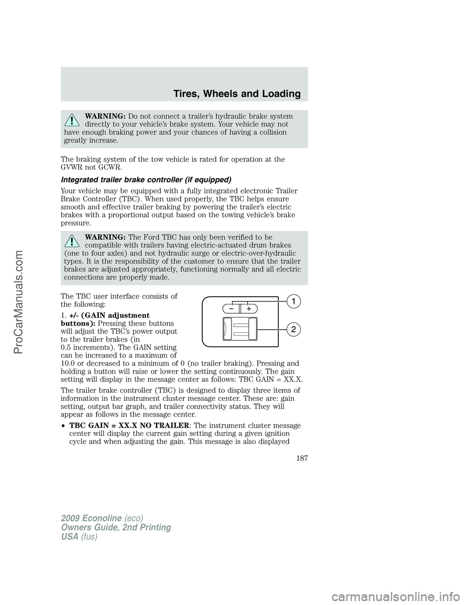
The TBC user interface consists of
the following:
1.+/- (GAIN adjustment
buttons):Pressing these buttons
will adjust the TBC’s power output
to the trailer brakes (in
0.5 increments). The GAIN setting
can be increased to a maximum of
10.0 or decreased to a minimum of 0 (no trailer braking). Pressing and
holding a button will raise or lower the setting continuously. The gain
setting will display in the message center as follows: TBC GAIN = XX.X.
The trailer brake controller (TBC) is designed to display three items of
information in the instrument cluster message center. These are: gain
setting, output bar graph, and trailer connectivity status. They will
appear as follows in the message center.
•TBC GAIN = XX.X NO TRAILER: The instrument cluster message
center will display the current gain setting during a given ignition
cycle and when adjusting the gain. This message is also displayed
2009 Econoline(eco)
Owners Guide, 2nd Printing
USA(fus)
Tires, Wheels and Loading
187
ProCarManuals.com
Page 188 of 320
during manual activation without a trailer connected or when gain
adjustments are made with no trailer connected.
•TBC GAIN = XX.X OUTPUT = //////: When the vehicle’s brake pedal
is pushed, or when the manual control is activated, bar indicators will
illuminate in the instrument cluster message center to indicate the
amount of power going to the trailer brakes relative to the brake pedal
or manual control input. One bar indicates the least amount of output
with six bars indicating maximum output.
•TRAILER CONNECTED:This message is displayed when a correct
trailer wiring connection (a trailer with electric trailer brakes) has
been sensed during a given ignition cycle.
•TRAILER DISCONNECTED:This message is displayed and
accompanied by a single chime, when a trailer connection was
determined and then a disconnection, either intentionally or
unintentionally, has been sensed during a given ignition cycle. It is also
displayed if a truck or trailer wiring fault occurs causing the trailer to
appear disconnected. This message is also displayed during manual
activation without a trailer connected.
2.Manual control lever:Slide the control lever to the left to activate
power to the trailer’s electric brakes independent of the tow vehicle’s
brakes (see the followingProcedure for adjusting GAINsection for
instructions on proper use of this feature). If the manual control is
activated while the brake is also applied, the greater of the two inputs
determines the power sent to the trailer brakes.
•Stop Lamps:Activating the TBC manual control lever will illuminate
both the trailer brake lamps and the tow vehicle brake lamps except
the Center High-Mount Stop Lamp (presuming proper trailer electrical
connection). Pressing the vehicle brake pedal will also illuminate both
trailer and vehicle brake lamps.
Procedure for adjusting GAIN:
The GAIN setting is used to set the TBC for the specific towing
condition and should be changed as towing conditions change. Changes
to towing conditions include trailer load, vehicle load, road conditions
and weather.
The GAIN should be set to provide the maximum trailer braking
assistance while ensuring the trailer wheels do not lock when braking.
Locked trailer wheels may lead to trailer instability.
Note:This should only be performed in a traffic free environment at
speeds of approximately 20–25 mph (30–40 km/h).
2009 Econoline(eco)
Owners Guide, 2nd Printing
USA(fus)
Tires, Wheels and Loading
188
ProCarManuals.com