relay FORD ESCAPE 2002 1.G Owners Manual
[x] Cancel search | Manufacturer: FORD, Model Year: 2002, Model line: ESCAPE, Model: FORD ESCAPE 2002 1.GPages: 280, PDF Size: 2.75 MB
Page 2 of 280
Seating and Safety Restraints 113
Seating 113
Safety restraints 125
Air bags 136
Child restraints 144
Driving 154
Starting 154
Brakes 158
Transmission operation 163
Vehicle loading 178
Trailer towing 181
Recreational towing 185
Roadside Emergencies 186
Getting roadside assistance 186
Hazard flasher switch 187
Fuel pump shut-off switch 187
Fuses and relays 189
Changing tires 195
Jump starting 200
Wrecker towing 206
Customer Assistance 208
The dispute settlement board 211
Utilizing the mediation/arbitration 214
Getting assistance outside the U.S. and Canada 214
Ordering additional owner's literature 215
Reporting safety defects (U.S. only) 217
Cleaning 218
Cleaning your vehicle 218
Underbody preservation 224
Table of Contents
2
Page 164 of 280
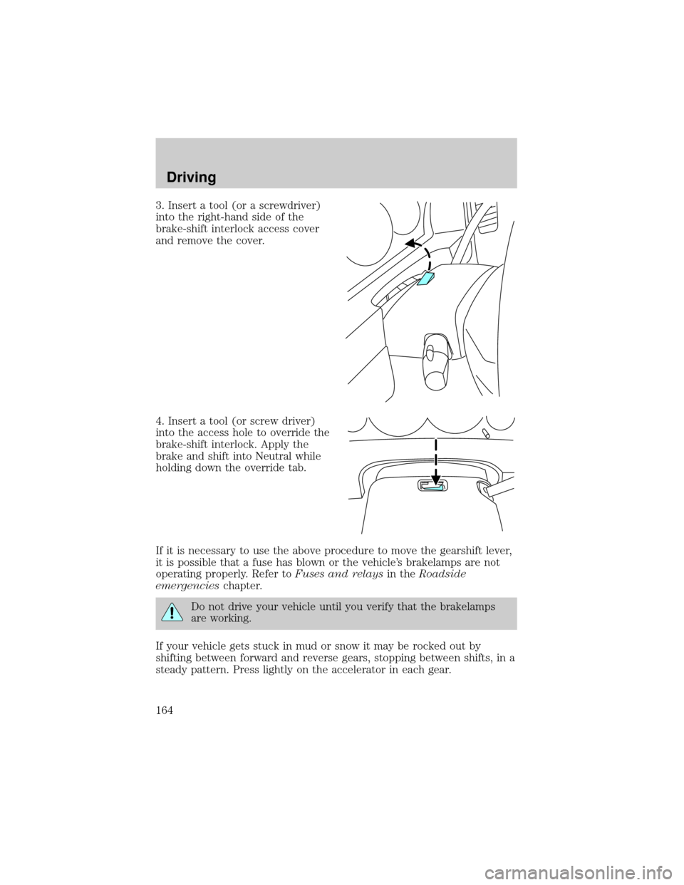
3. Insert a tool (or a screwdriver)
into the right-hand side of the
brake-shift interlock access cover
and remove the cover.
4. Insert a tool (or screw driver)
into the access hole to override the
brake-shift interlock. Apply the
brake and shift into Neutral while
holding down the override tab.
If it is necessary to use the above procedure to move the gearshift lever,
it is possible that a fuse has blown or the vehicle's brakelamps are not
operating properly. Refer toFuses and relaysin theRoadside
emergencieschapter.
Do not drive your vehicle until you verify that the brakelamps
are working.
If your vehicle gets stuck in mud or snow it may be rocked out by
shifting between forward and reverse gears, stopping between shifts, in a
steady pattern. Press lightly on the accelerator in each gear.
Driving
164
Page 189 of 280
FUSES AND RELAYS
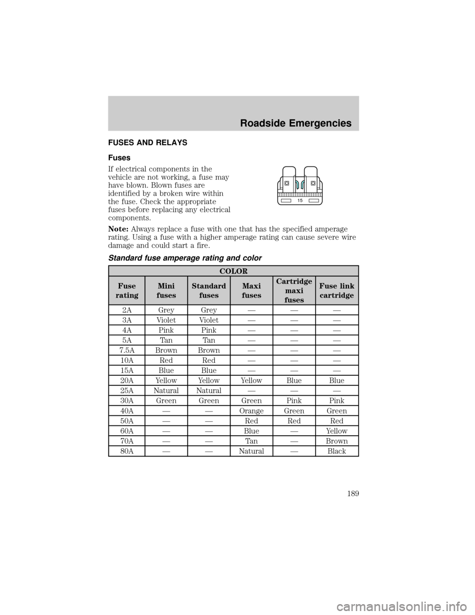
Fuses
If electrical components in the
vehicle are not working, a fuse may
have blown. Blown fuses are
identified by a broken wire within
the fuse. Check the appropriate
fuses before replacing any electrical
components.
Note:Always replace a fuse with one that has the specified amperage
rating. Using a fuse with a higher amperage rating can cause severe wire
damage and could start a fire.
Standard fuse amperage rating and color
COLOR
Fuse
ratingMini
fusesStandard
fusesMaxi
fusesCartridge
maxi
fusesFuse link
cartridge
2A Grey Grey Ð Ð Ð
3A Violet Violet Ð Ð Ð
4A Pink Pink Ð Ð Ð
5A Tan Tan Ð Ð Ð
7.5A Brown Brown Ð Ð Ð
10A Red Red Ð Ð Ð
15A Blue Blue Ð Ð Ð
20A Yellow Yellow Yellow Blue Blue
25A Natural Natural Ð Ð Ð
30A Green Green Green Pink Pink
40A Ð Ð Orange Green Green
50A Ð Ð Red Red Red
60A Ð Ð Blue Ð Yellow
70A Ð Ð Tan Ð Brown
80A Ð Ð Natural Ð Black
15
Roadside Emergencies
189
Page 190 of 280
Passenger compartment fuse panel
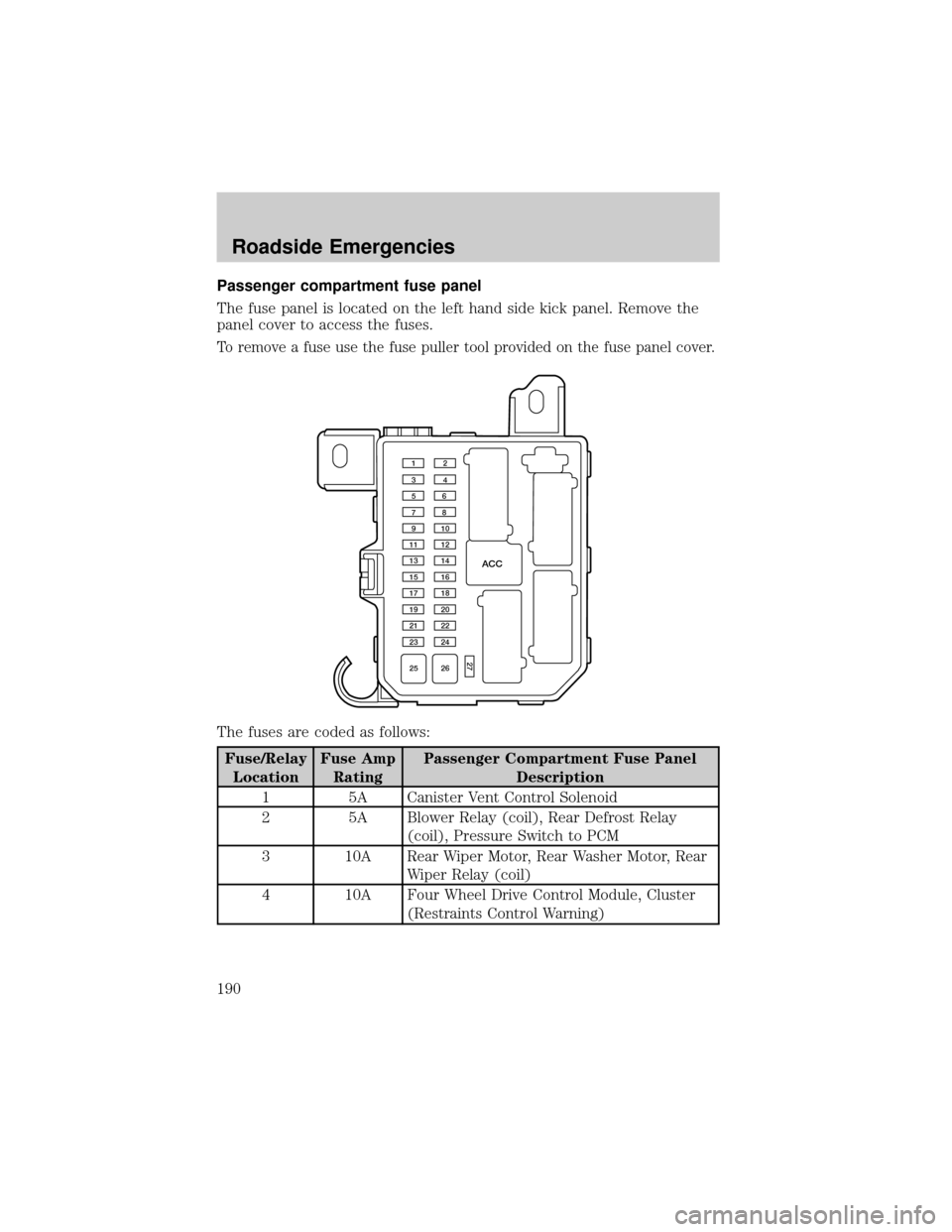
The fuse panel is located on the left hand side kick panel. Remove the
panel cover to access the fuses.
To remove a fuse use the fuse puller tool provided on the fuse panel cover.
The fuses are coded as follows:
Fuse/Relay
LocationFuse Amp
RatingPassenger Compartment Fuse Panel
Description
1 5A Canister Vent Control Solenoid
2 5A Blower Relay (coil), Rear Defrost Relay
(coil), Pressure Switch to PCM
3 10A Rear Wiper Motor, Rear Washer Motor, Rear
Wiper Relay (coil)
4 10A Four Wheel Drive Control Module, Cluster
(Restraints Control Warning)
ACC
12
34
56
78
910
11 12
13 14
15 16
17 18
19 20
21 22
23 24
25 26
27
Roadside Emergencies
190
Page 191 of 280
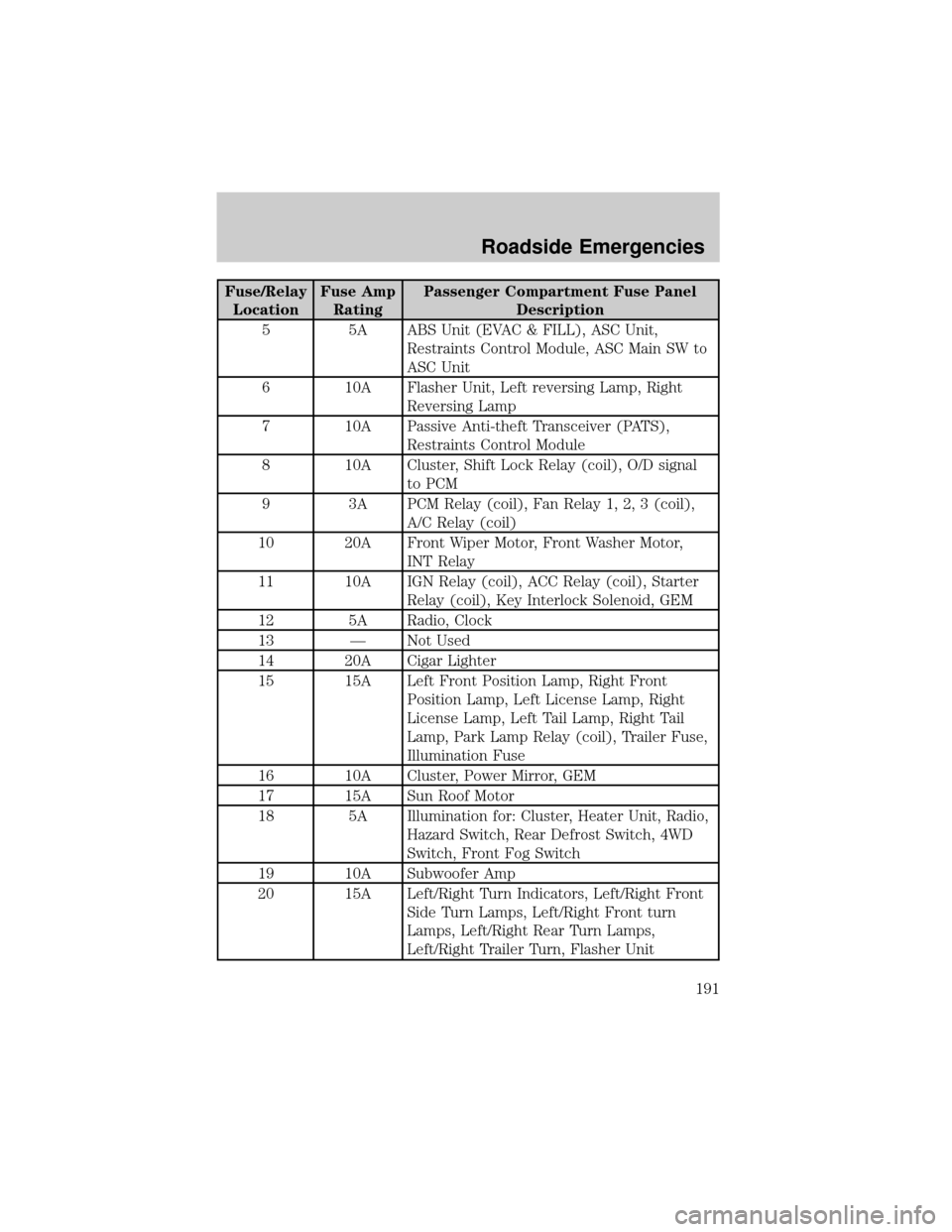
Fuse/Relay
LocationFuse Amp
RatingPassenger Compartment Fuse Panel
Description
5 5A ABS Unit (EVAC & FILL), ASC Unit,
Restraints Control Module, ASC Main SW to
ASC Unit
6 10A Flasher Unit, Left reversing Lamp, Right
Reversing Lamp
7 10A Passive Anti-theft Transceiver (PATS),
Restraints Control Module
8 10A Cluster, Shift Lock Relay (coil), O/D signal
to PCM
9 3A PCM Relay (coil), Fan Relay 1, 2, 3 (coil),
A/C Relay (coil)
10 20A Front Wiper Motor, Front Washer Motor,
INT Relay
11 10A IGN Relay (coil), ACC Relay (coil), Starter
Relay (coil), Key Interlock Solenoid, GEM
12 5A Radio, Clock
13 Ð Not Used
14 20A Cigar Lighter
15 15A Left Front Position Lamp, Right Front
Position Lamp, Left License Lamp, Right
License Lamp, Left Tail Lamp, Right Tail
Lamp, Park Lamp Relay (coil), Trailer Fuse,
Illumination Fuse
16 10A Cluster, Power Mirror, GEM
17 15A Sun Roof Motor
18 5A Illumination for: Cluster, Heater Unit, Radio,
Hazard Switch, Rear Defrost Switch, 4WD
Switch, Front Fog Switch
19 10A Subwoofer Amp
20 15A Left/Right Turn Indicators, Left/Right Front
Side Turn Lamps, Left/Right Front turn
Lamps, Left/Right Rear Turn Lamps,
Left/Right Trailer Turn, Flasher Unit
Roadside Emergencies
191
Page 192 of 280
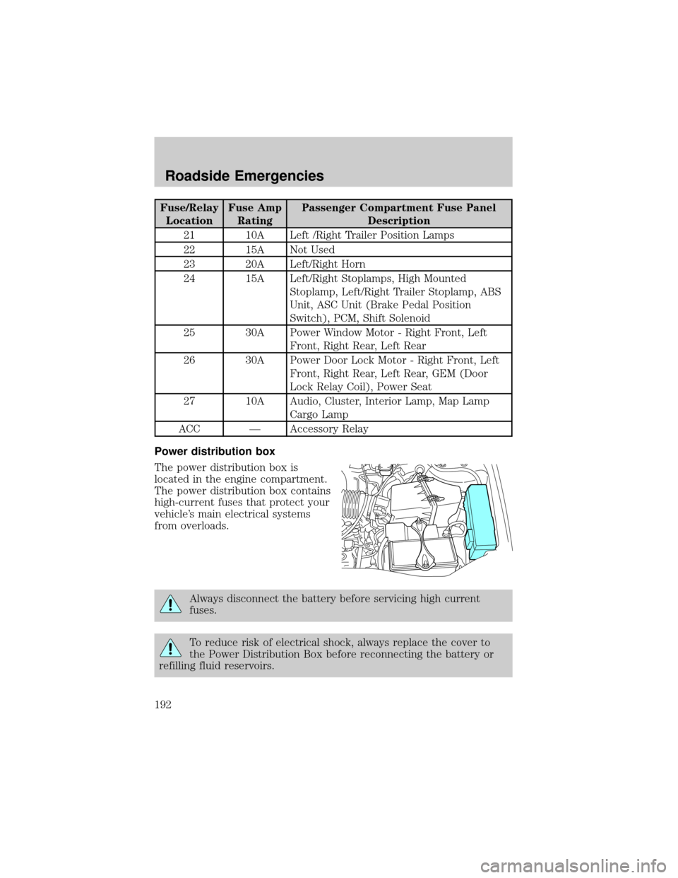
Fuse/Relay
LocationFuse Amp
RatingPassenger Compartment Fuse Panel
Description
21 10A Left /Right Trailer Position Lamps
22 15A Not Used
23 20A Left/Right Horn
24 15A Left/Right Stoplamps, High Mounted
Stoplamp, Left/Right Trailer Stoplamp, ABS
Unit, ASC Unit (Brake Pedal Position
Switch), PCM, Shift Solenoid
25 30A Power Window Motor - Right Front, Left
Front, Right Rear, Left Rear
26 30A Power Door Lock Motor - Right Front, Left
Front, Right Rear, Left Rear, GEM (Door
Lock Relay Coil), Power Seat
27 10A Audio, Cluster, Interior Lamp, Map Lamp
Cargo Lamp
ACC Ð Accessory Relay
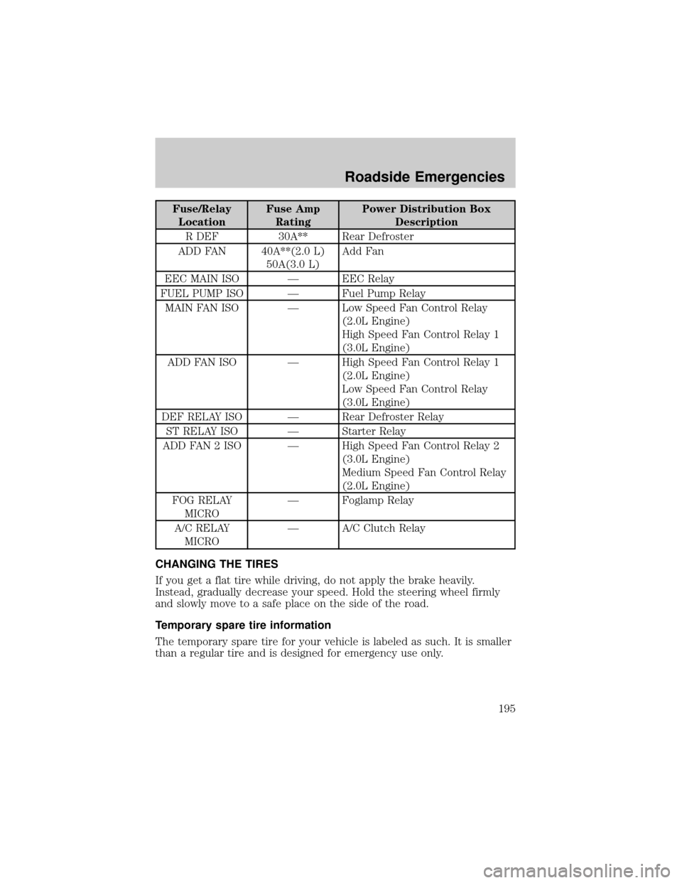
Power distribution box
The power distribution box is
located in the engine compartment.
The power distribution box contains
high-current fuses that protect your
vehicle's main electrical systems
from overloads.
Always disconnect the battery before servicing high current
fuses.
To reduce risk of electrical shock, always replace the cover to
the Power Distribution Box before reconnecting the battery or
refilling fluid reservoirs.
Roadside Emergencies
192
Page 193 of 280
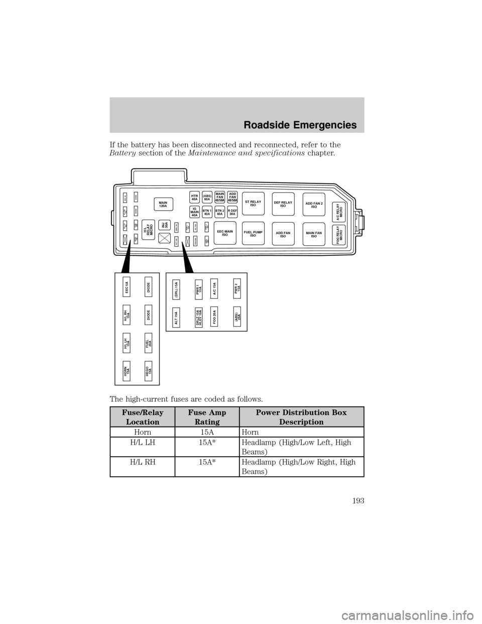
If the battery has been disconnected and reconnected, refer to the
Batterysection of theMaintenance and specificationschapter.
The high-current fuses are coded as follows.
Fuse/Relay
LocationFuse Amp
RatingPower Distribution Box
Description
Horn 15A Horn
H/L LH 15A* Headlamp (High/Low Left, High
Beams)
H/L RH 15A* Headlamp (High/Low Right, High
Beams)
MAIN
120A
HEGO
15A
ALT 15A
FOG 20A(DRL) 5A
PWR 1
15A
(ABS)
25APWR 2
15A A/C 15AFUEL
20ADIODE DIODE H/L LH
15AH/L RH
15AEEC 5A
HEGO
15A HORN
15A
FUEL
20ADIODE DIODE H/L LH
15AH/L RH
15AEEC 5A
INJ
30A
HTR
40A
BTN 1
40ABTN 240AR DEF30AIG
MAIN
40A
H/L
RELAY
MICRO
MAIN
FAN(ABS)
60AST RELAY
ISODEF RELAY
ISOADD FAN 2
ISO
A/C RELAY
MICRO FOG RELAY
MICRO
MAIN FAN
ISO ADD FAN
ISO EEC MAIN
ISOFUEL PUMP
ISO
ALT 15A
FOG 20A(DRL) 15A
PWR 1
15A DRLZ 15A
HLEV 10A
(ABS)
25APWR 2
15A A/C 15A
40/50AADD
FAN
40/50A
Roadside Emergencies
193
Page 194 of 280
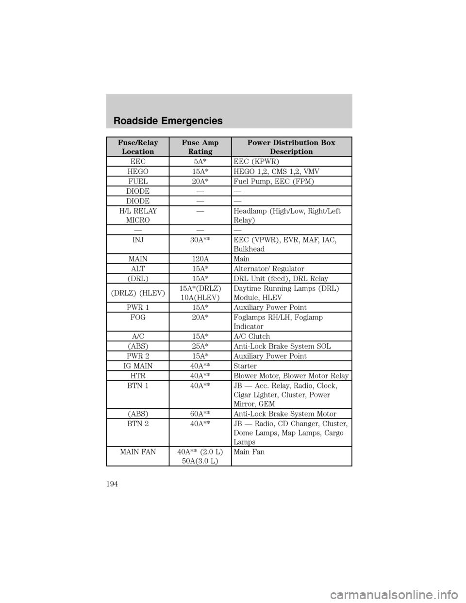
Fuse/Relay
LocationFuse Amp
RatingPower Distribution Box
Description
EEC 5A* EEC (KPWR)
HEGO 15A* HEGO 1,2, CMS 1,2, VMV
FUEL 20A* Fuel Pump, EEC (FPM)
DIODE Ð Ð
DIODE Ð Ð
H/L RELAY
MICROÐ Headlamp (High/Low, Right/Left
Relay)
ÐÐÐ
INJ 30A** EEC (VPWR), EVR, MAF, IAC,
Bulkhead
MAIN 120A Main
ALT 15A* Alternator/ Regulator
(DRL) 15A* DRL Unit (feed), DRL Relay
(DRLZ) (HLEV)15A*(DRLZ)
10A(HLEV)Daytime Running Lamps (DRL)
Module, HLEV
PWR 1 15A* Auxiliary Power Point
FOG 20A* Foglamps RH/LH, Foglamp
Indicator
A/C 15A* A/C Clutch
(ABS) 25A* Anti-Lock Brake System SOL
PWR 2 15A* Auxiliary Power Point
IG MAIN 40A** Starter
HTR 40A** Blower Motor, Blower Motor Relay
BTN 1 40A** JB Ð Acc. Relay, Radio, Clock,
Cigar Lighter, Cluster, Power
Mirror, GEM
(ABS) 60A** Anti-Lock Brake System Motor
BTN 2 40A** JB Ð Radio, CD Changer, Cluster,
Dome Lamps, Map Lamps, Cargo
Lamps
MAIN FAN 40A** (2.0 L)
50A(3.0 L)Main Fan
Roadside Emergencies
194
Page 195 of 280
Fuse/Relay
LocationFuse Amp
RatingPower Distribution Box
Description
R DEF 30A** Rear Defroster
ADD FAN 40A**(2.0 L)
50A(3.0 L)Add Fan
EEC MAIN ISO Ð EEC Relay
FUEL PUMP ISO Ð Fuel Pump Relay
MAIN FAN ISO Ð Low Speed Fan Control Relay
(2.0L Engine)
High Speed Fan Control Relay 1
(3.0L Engine)
ADD FAN ISO Ð High Speed Fan Control Relay 1
(2.0L Engine)
Low Speed Fan Control Relay
(3.0L Engine)
DEF RELAY ISO Ð Rear Defroster Relay
ST RELAY ISO Ð Starter Relay
ADD FAN 2 ISO Ð High Speed Fan Control Relay 2
(3.0L Engine)
Medium Speed Fan Control Relay
(2.0L Engine)
FOG RELAY
MICROÐ Foglamp Relay
A/C RELAY
MICROÐ A/C Clutch Relay
CHANGING THE TIRES
If you get a flat tire while driving, do not apply the brake heavily.
Instead, gradually decrease your speed. Hold the steering wheel firmly
and slowly move to a safe place on the side of the road.
Temporary spare tire information
The temporary spare tire for your vehicle is labeled as such. It is smaller
than a regular tire and is designed for emergency use only.
Roadside Emergencies
195
Page 278 of 280

low fuel ......................................13
oil pressure ...............................12
overdrive off ..............................13
safety belt .................................12
service engine soon ..................10
turn signal indicator .................13
Load limits .................................178
GAWR ......................................178
GVWR ......................................178
trailer towing ..........................178
Loading instructions .................180
Locks
childproof ................................103
Lubricant specifications ...265, 267
Lumbar support, seats .............115
M
Manual transaxle
fluid, checking and adding ....256
Manual transmission
fluid capacities ........................262
lubricant specifications ..........267
Mirrors
fold away ...................................86
side view mirrors (power) .......85
Moon roof ....................................89
Motorcraft parts ................246, 262
O
Octane rating ............................245
Odometer .....................................17
Oil (see Engine oil) ..................231
Overdrive ...................................165P
Panic alarm feature, remote
entry system ..............................104
Parking brake ............................160
Parts (see Motorcraft parts) ....262
Power distribution box
(see Fuses) ...............................192
Power door locks ......................102
Power mirrors .............................85
Power steering ..........................161
fluid, checking and adding ....252
fluid, refill capacity ................262
fluid, specifications .........265, 267
Power Windows ...........................83
Preparing to drive your
vehicle ........................................162
R
Radio ......................................25, 46
Radio reception ...........................61
Rear window defroster ...............67
Relays ........................................189
Remote entry system .......103±104
illuminated entry ....................106
locking/unlocking
doors ................................102, 104
panic alarm .............................104
replacement/additional
transmitters .............................105
replacing the batteries ...........105
Roadside assistance ..................186
Roof rack .....................................92
Index
278