Cluster FORD ESCAPE 2003 1.G User Guide
[x] Cancel search | Manufacturer: FORD, Model Year: 2003, Model line: ESCAPE, Model: FORD ESCAPE 2003 1.GPages: 240, PDF Size: 2.6 MB
Page 101 of 240
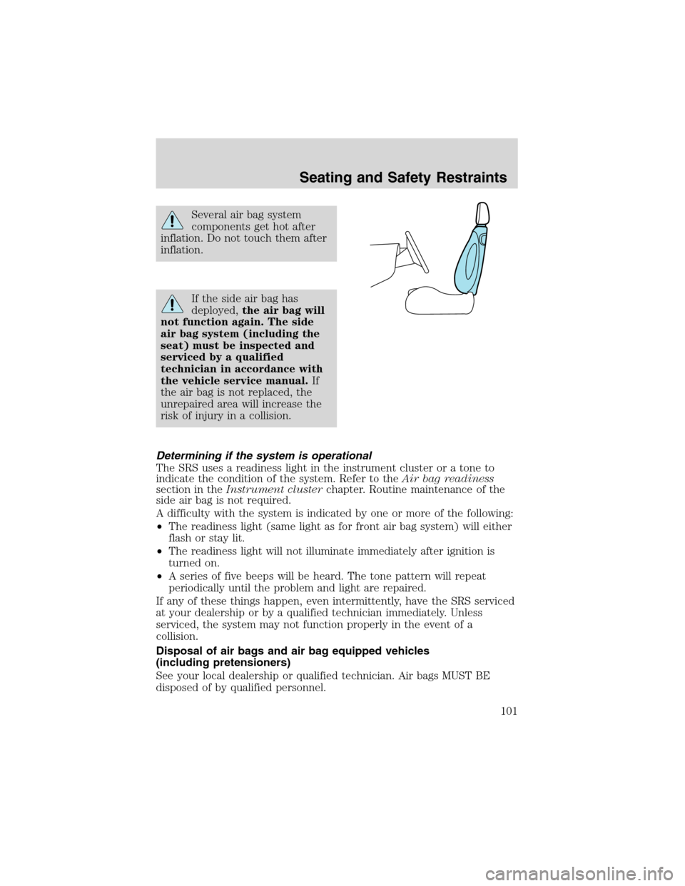
Several air bag system
components get hot after
inflation. Do not touch them after
inflation.
If the side air bag has
deployed,the air bag will
not function again. The side
air bag system (including the
seat) must be inspected and
serviced by a qualified
technician in accordance with
the vehicle service manual.If
the air bag is not replaced, the
unrepaired area will increase the
risk of injury in a collision.
Determining if the system is operational
The SRS uses a readiness light in the instrument cluster or a tone to
indicate the condition of the system. Refer to theAir bag readiness
section in theInstrument clusterchapter. Routine maintenance of the
side air bag is not required.
A difficulty with the system is indicated by one or more of the following:
•The readiness light (same light as for front air bag system) will either
flash or stay lit.
•The readiness light will not illuminate immediately after ignition is
turned on.
•A series of five beeps will be heard. The tone pattern will repeat
periodically until the problem and light are repaired.
If any of these things happen, even intermittently, have the SRS serviced
at your dealership or by a qualified technician immediately. Unless
serviced, the system may not function properly in the event of a
collision.
Disposal of air bags and air bag equipped vehicles
(including pretensioners)
See your local dealership or qualified technician. Air bags MUST BE
disposed of by qualified personnel.
Seating and Safety Restraints
101
Page 118 of 240
BRAKES
Occasional brake noise is normal. If a metal-to-metal, continuous grinding
or continuous squeal sound is present, the brake linings may be worn-out
and should be inspected by a qualified service technician. If the vehicle
has continuous vibration or shudder in the steering wheel while braking,
the vehicle should be inspected by a qualified service technician.
Brakes
Under normal operating conditions, brake dust may accumulate on the
wheels. Some brake dust is inevitable as brakes wear and does not
contribute to brake noise. The use of modern friction materials with
emphasis on improved performance and environmental considerations
can lead to more dust than in the past. Brake dust can be cleaned by
weekly washing with soapy water and a soft sponge. Heavier deposits can
be removed with Motorcraft Wheel and Tire Cleaner (ZC-37–A).
Four-wheel anti-lock brake system (ABS) (if equipped)
Your vehicle may be equipped with an Anti-lock Braking System (ABS).
This system helps you maintain steering control during emergency stops
by keeping the brakes from locking. Noise from the ABS pump motor
and brake pedal pulsation may be observed during ABS braking; any
pulsation or mechanical noise you may feel or hear is normal.
Using ABS
When hard braking is required, apply continuous force on the brake
pedal; do not pump the brake pedal since this will reduce the
effectiveness of the ABS and will increase your vehicle’s stopping
distance. The ABS will be activated immediately, allowing you to retain
full steering control during hard braking and on slippery surfaces.
However, the ABS does not decrease stopping distance.
ABS warning lamp
ABS
TheABSlamp in the instrument cluster momentarily illuminates when
the ignition is turned to ON. If the light does not illuminate during start
up, remains on or flashes, the ABS may be disabled and the ABS may
need to be serviced
Even when the ABS is disabled,
normal braking is still effective. (If
your BRAKE warning lamp
illuminates with the parking brake
released, have your brake system
serviced immediately.)
!
BRAKE
Driving
118
Page 149 of 240
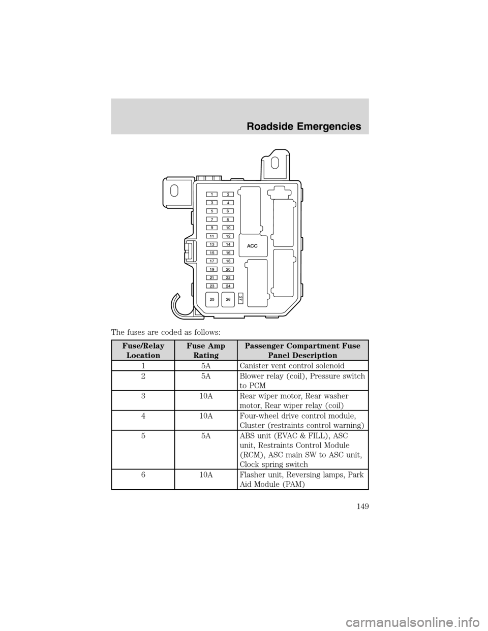
The fuses are coded as follows:
Fuse/Relay
LocationFuse Amp
RatingPassenger Compartment Fuse
Panel Description
1 5A Canister vent control solenoid
2 5A Blower relay (coil), Pressure switch
to PCM
3 10A Rear wiper motor, Rear washer
motor, Rear wiper relay (coil)
4 10A Four-wheel drive control module,
Cluster (restraints control warning)
5 5A ABS unit (EVAC & FILL), ASC
unit, Restraints Control Module
(RCM), ASC main SW to ASC unit,
Clock spring switch
6 10A Flasher unit, Reversing lamps, Park
Aid Module (PAM)
ACC
12
34
56
78
910
11 12
13 14
15 16
17 18
19 20
21 22
23 24
25 26
27
Roadside Emergencies
149
Page 150 of 240
Fuse/Relay
LocationFuse Amp
RatingPassenger Compartment Fuse
Panel Description
7 10A Passive Anti-theft Transceiver
(PATS), RCM, EEC fuse
8 10A Cluster, Shift lock relay (coil), O/D
signal to PCM, GEM, E/C autolamp
mirror
9 3A PCM relay (coil), Fan relay 1, 2, 3
(coil), A/C relay (coil)
10 20A Front wiper motor, Front washer
motor
11 10A ACC relay (coil), Key interlock
solenoid, GEM
12 5A Radio
13—Not used
14 20A Cigar lighter
15 15A Park lamp relay, Front position
lamps, License lamps, Tail lamps,
Park lamp relay (coil), Trailer fuse,
Illumination fuse
16 10A Cluster, Power mirror, GEM,
Heated seats
17 15A Sun roof motor
18 5A Illumination for: Cluster, Heater
unit, Radio, Hazard switch, Rear
defrost switch, 4WD switch, Front
fog switch
19 10A Subwoofer amp
20 15A Turn Indicators, Front Side Turn
Lamps, Front turn lamps, Rear turn
lamps, Trailer turn, Flasher unit
21 10A Trailer position lamps
22 15A Not used
23 20A Horn relay
Roadside Emergencies
150
Page 151 of 240
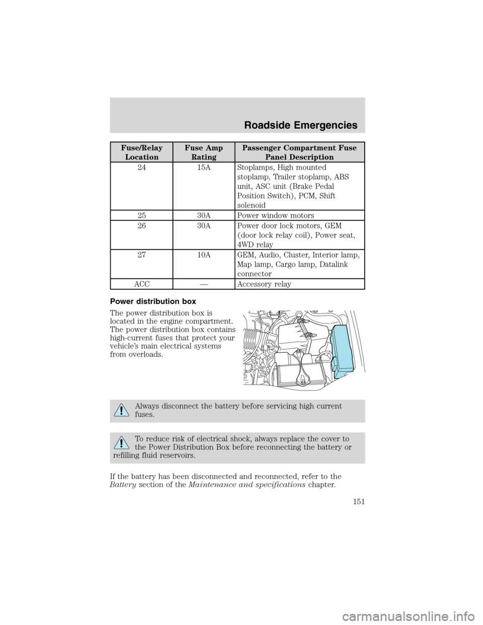
Fuse/Relay
LocationFuse Amp
RatingPassenger Compartment Fuse
Panel Description
24 15A Stoplamps, High mounted
stoplamp, Trailer stoplamp, ABS
unit, ASC unit (Brake Pedal
Position Switch), PCM, Shift
solenoid
25 30A Power window motors
26 30A Power door lock motors, GEM
(door lock relay coil), Power seat,
4WD relay
27 10A GEM, Audio, Cluster, Interior lamp,
Map lamp, Cargo lamp, Datalink
connector
ACC—Accessory relay
Power distribution box
The power distribution box is
located in the engine compartment.
The power distribution box contains
high-current fuses that protect your
vehicle’s main electrical systems
from overloads.
Always disconnect the battery before servicing high current
fuses.
To reduce risk of electrical shock, always replace the cover to
the Power Distribution Box before reconnecting the battery or
refilling fluid reservoirs.
If the battery has been disconnected and reconnected, refer to the
Batterysection of theMaintenance and specificationschapter.
Roadside Emergencies
151
Page 153 of 240
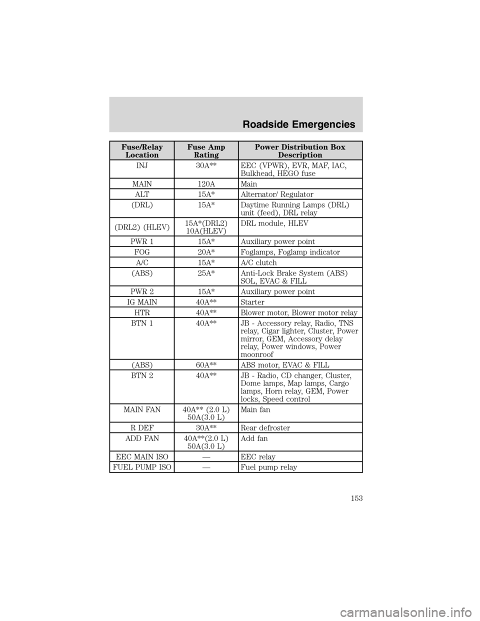
Fuse/Relay
LocationFuse Amp
RatingPower Distribution Box
Description
INJ 30A** EEC (VPWR), EVR, MAF, IAC,
Bulkhead, HEGO fuse
MAIN 120A Main
ALT 15A* Alternator/ Regulator
(DRL) 15A* Daytime Running Lamps (DRL)
unit (feed), DRL relay
(DRL2) (HLEV)15A*(DRL2)
10A(HLEV)DRL module, HLEV
PWR 1 15A* Auxiliary power point
FOG 20A* Foglamps, Foglamp indicator
A/C 15A* A/C clutch
(ABS) 25A* Anti-Lock Brake System (ABS)
SOL, EVAC & FILL
PWR 2 15A* Auxiliary power point
IG MAIN 40A** Starter
HTR 40A** Blower motor, Blower motor relay
BTN 1 40A** JB - Accessory relay, Radio, TNS
relay, Cigar lighter, Cluster, Power
mirror, GEM, Accessory delay
relay, Power windows, Power
moonroof
(ABS) 60A** ABS motor, EVAC & FILL
BTN 2 40A** JB - Radio, CD changer, Cluster,
Dome lamps, Map lamps, Cargo
lamps, Horn relay, GEM, Power
locks, Speed control
MAIN FAN 40A** (2.0 L)
50A(3.0 L)Main fan
R DEF 30A** Rear defroster
ADD FAN 40A**(2.0 L)
50A(3.0 L)Add fan
EEC MAIN ISO—EEC relay
FUEL PUMP ISO—Fuel pump relay
Roadside Emergencies
153
Page 180 of 240
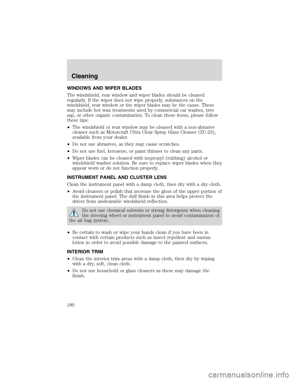
WINDOWS AND WIPER BLADES
The windshield, rear window and wiper blades should be cleaned
regularly. If the wiper does not wipe properly, substances on the
windshield, rear window or the wiper blades may be the cause. These
may include hot wax treatments used by commercial car washes, tree
sap, or other organic contamination. To clean these items, please follow
these tips:
•The windshield or rear window may be cleaned with a non-abrasive
cleaner such as Motorcraft Ultra Clear Spray Glass Cleaner (ZC-23),
available from your dealer.
•Do not use abrasives, as they may cause scratches.
•Do not use fuel, kerosene, or paint thinner to clean any parts.
•Wiper blades can be cleaned with isopropyl (rubbing) alcohol or
windshield washer solution. Be sure to replace wiper blades when they
appear worn or do not function properly.
INSTRUMENT PANEL AND CLUSTER LENS
Clean the instrument panel with a damp cloth, then dry with a dry cloth.
•Avoid cleaners or polish that increase the gloss of the upper portion of
the instrument panel. The dull finish in this area helps protect the
driver from undesirable windshield reflection.
Do not use chemical solvents or strong detergents when cleaning
the steering wheel or instrument panel to avoid contamination of
the air bag system.
•Be certain to wash or wipe your hands clean if you have been in
contact with certain products such as insect repellent and suntan
lotion in order to avoid possible damage to the painted surfaces.
INTERIOR TRIM
•Clean the interior trim areas with a damp cloth, then dry by wiping
with a dry, soft, clean cloth.
•Do not use household or glass cleaners as these may damage the
finish.
Cleaning
180
Page 203 of 240
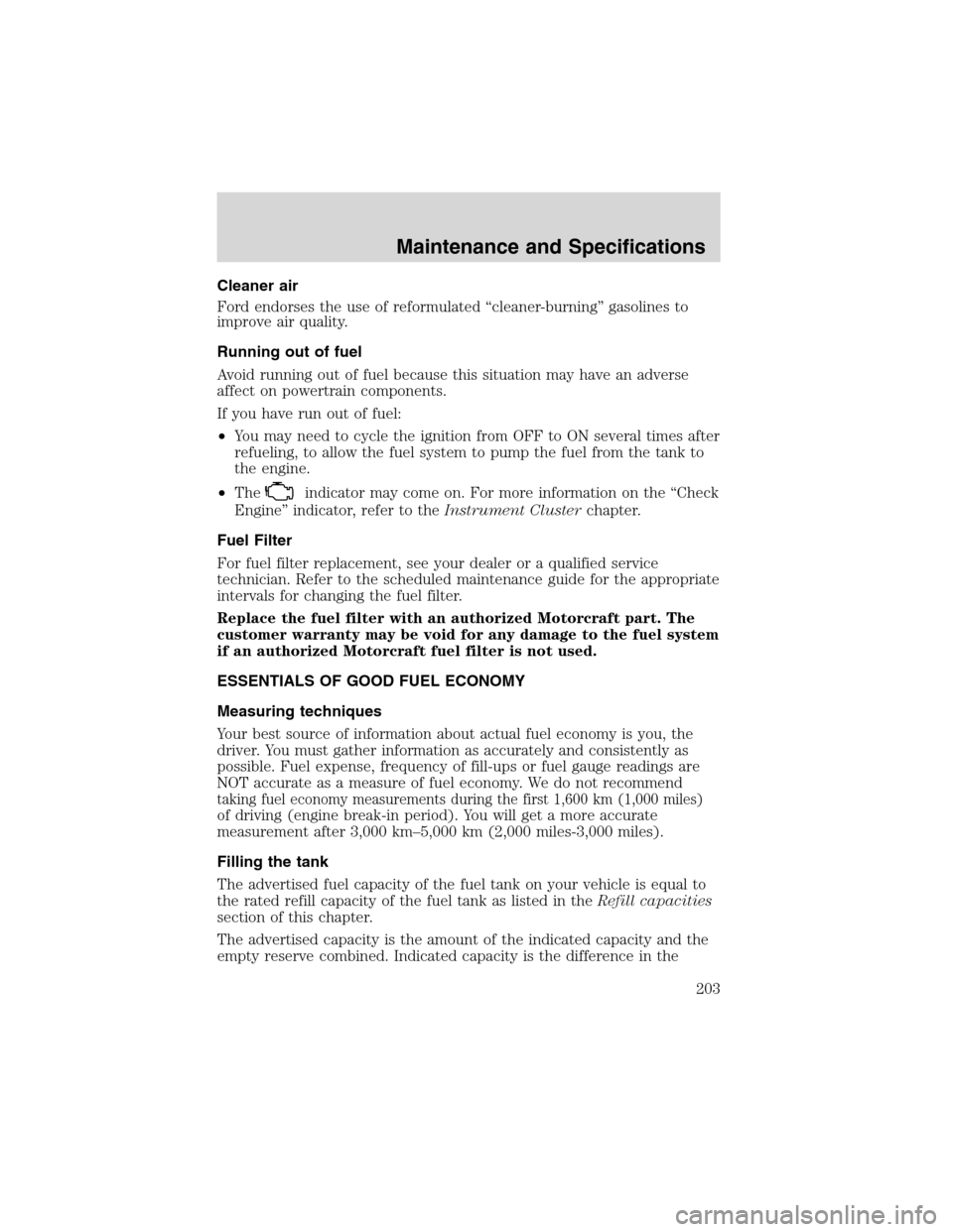
Cleaner air
Ford endorses the use of reformulated“cleaner-burning”gasolines to
improve air quality.
Running out of fuel
Avoid running out of fuel because this situation may have an adverse
affect on powertrain components.
If you have run out of fuel:
•You may need to cycle the ignition from OFF to ON several times after
refueling, to allow the fuel system to pump the fuel from the tank to
the engine.
•The
indicator may come on. For more information on the“Check
Engine”indicator, refer to theInstrument Clusterchapter.
Fuel Filter
For fuel filter replacement, see your dealer or a qualified service
technician. Refer to the scheduled maintenance guide for the appropriate
intervals for changing the fuel filter.
Replace the fuel filter with an authorized Motorcraft part. The
customer warranty may be void for any damage to the fuel system
if an authorized Motorcraft fuel filter is not used.
ESSENTIALS OF GOOD FUEL ECONOMY
Measuring techniques
Your best source of information about actual fuel economy is you, the
driver. You must gather information as accurately and consistently as
possible. Fuel expense, frequency of fill-ups or fuel gauge readings are
NOT accurate as a measure of fuel economy. We do not recommend
taking fuel economy measurements during the first 1,600 km (1,000 miles)
of driving (engine break-in period). You will get a more accurate
measurement after 3,000 km–5,000 km (2,000 miles-3,000 miles).
Filling the tank
The advertised fuel capacity of the fuel tank on your vehicle is equal to
the rated refill capacity of the fuel tank as listed in theRefill capacities
section of this chapter.
The advertised capacity is the amount of the indicated capacity and the
empty reserve combined. Indicated capacity is the difference in the
Maintenance and Specifications
203
Page 207 of 240
•Do not turn off the ignition while your vehicle is moving, especially at
high speeds.
•Have the items listed in your scheduled maintenance guide performed
according to the specified schedule.
The scheduled maintenance items listed in the scheduled maintenance
guide are essential to the life and performance of your vehicle and to its
emissions system.
If other than Ford, Motorcraft or Ford-authorized parts are used for
maintenance replacements or for service of components affecting
emission control, such non-Ford parts should be equivalent to genuine
Ford Motor Company parts in performance and durability.
Do not park, idle, or drive your vehicle in dry grass or other dry
ground cover. The emission system heats up the engine
compartment and exhaust system, which can start a fire.
Illumination of the
indicator, charging system warning light or the
temperature warning light, fluid leaks, strange odors, smoke or loss of
engine power, could indicate that the emission control system is not
working properly.
Exhaust leaks may result in entry of harmful and potentially
lethal fumes into the passenger compartment.
Do not make any unauthorized changes to your vehicle or engine. By
law, vehicle owners and anyone who manufactures, repairs, services,
sells, leases, trades vehicles, or supervises a fleet of vehicles are not
permitted to intentionally remove an emission control device or prevent
it from working. Information about your vehicle’s emission system is on
the Vehicle Emission Control Information Decal located on or near the
engine. This decal identifies engine displacement and gives some tune up
specifications.
Please consult yourWarranty Guidefor complete emission warranty
information.
Readiness for Inspection/Maintenance (I/M) testing
In some localities, it may be a legal requirement to pass an I/M test of
the on-board diagnostics system. If your
indicator is on, refer to the
description in theWarning lights and chimessection of the
Instrument Clusterchapter. Your vehicle may not pass the I/M test with
the
indicator on.
Maintenance and Specifications
207
Page 233 of 240
Exhaust fumes ..........................117
F
Fluid capacities .........................218
Foglamps .....................................33
Four-Wheel Drive vehicles
driving off road .......................129
indicator light .........................128
preparing to drive your
vehicle .....................................119
Fuel ............................................199
calculating fuel economy .......203
cap ...........................................201
capacity ...................................218
choosing the right fuel ...........201
comparisons with EPA fuel
economy estimates .................206
detergent in fuel .....................203
filling your vehicle with
fuel ...........................199, 201, 203
filter, specifications ........203, 218
fuel pump shut-off switch .....146
improving fuel economy ........203
octane rating ...................202, 223
quality ......................................202
running out of fuel .................203
safety information relating to
automotive fuels .....................199
Fuses ..................................147–148
G
Garage door opener ....................46
Gas cap (see Fuel cap) ............201
Gas mileage (see Fuel
economy) ...................................203
Gauges .........................................13
GAWR (Gross Axle Weight
Rating) .......................................139calculating ...............................141
definition .................................139
driving with a heavy load ......139
location ....................................139
GVWR (Gross Vehicle Weight
Rating) .......................................139
calculating .......................139, 141
definition .................................139
driving with a heavy load ......139
location ....................................139
H
Hazard flashers .........................146
Head restraints .....................75, 77
Headlamps ...................................33
aiming ........................................35
autolamp system .................33, 46
bulb specifications ....................38
daytime running lights .............33
flash to pass ..............................34
high beam .................................34
replacing bulbs .........................39
turning on and off ....................33
Heating
heater only system ...................30
Hood ..........................................184
I
Ignition ...............................114, 223
Infant seats
(see Safety seats) .....................105
Inspection/maintenance (I/M)
testing ........................................207
Instrument panel
cleaning ...................................180
cluster ........................................10
lighting up panel and
interior .......................................34
Index
233