ABS FORD ESCAPE 2004 1.G Owners Manual
[x] Cancel search | Manufacturer: FORD, Model Year: 2004, Model line: ESCAPE, Model: FORD ESCAPE 2004 1.GPages: 240, PDF Size: 2.5 MB
Page 11 of 240
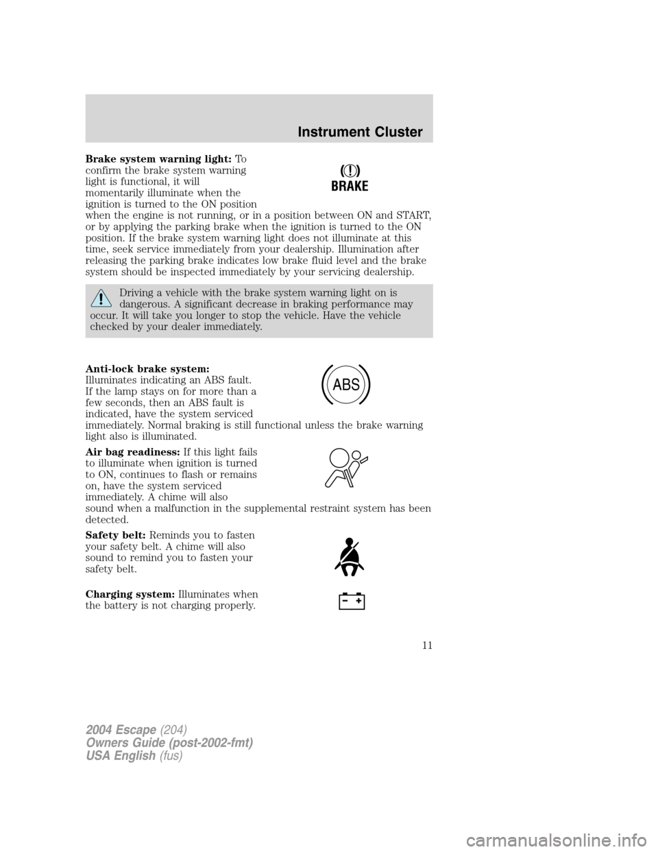
Brake system warning light:To
confirm the brake system warning
light is functional, it will
momentarily illuminate when the
ignition is turned to the ON position
when the engine is not running, or in a position between ON and START,
or by applying the parking brake when the ignition is turned to the ON
position. If the brake system warning light does not illuminate at this
time, seek service immediately from your dealership. Illumination after
releasing the parking brake indicates low brake fluid level and the brake
system should be inspected immediately by your servicing dealership.
Driving a vehicle with the brake system warning light on is
dangerous. A significant decrease in braking performance may
occur. It will take you longer to stop the vehicle. Have the vehicle
checked by your dealer immediately.
Anti-lock brake system:
Illuminates indicating an ABS fault.
If the lamp stays on for more than a
few seconds, then an ABS fault is
indicated, have the system serviced
immediately. Normal braking is still functional unless the brake warning
light also is illuminated.
Air bag readiness:If this light fails
to illuminate when ignition is turned
to ON, continues to flash or remains
on, have the system serviced
immediately. A chime will also
sound when a malfunction in the supplemental restraint system has been
detected.
Safety belt:Reminds you to fasten
your safety belt. A chime will also
sound to remind you to fasten your
safety belt.
Charging system:Illuminates when
the battery is not charging properly.
!
BRAKE
ABS
2004 Escape(204)
Owners Guide (post-2002-fmt)
USA English(fus)
Instrument Cluster
11
Page 40 of 240

Replacing headlamp bulbs
1. Make sure that the headlamp control is in the OFF position.
2. Open the hood.
3. Press two tabs and disconnect the
electrical connector from the bulb.
4. Remove the rubber boot from the
lamp assembly by pulling on one of
the tabs.
5. Press the retainer spring forward
and spread the spring releasing it
from bulb hooks and rotate it away
from the bulb.
2004 Escape(204)
Owners Guide (post-2002-fmt)
USA English(fus)
Lights
40
Page 41 of 240
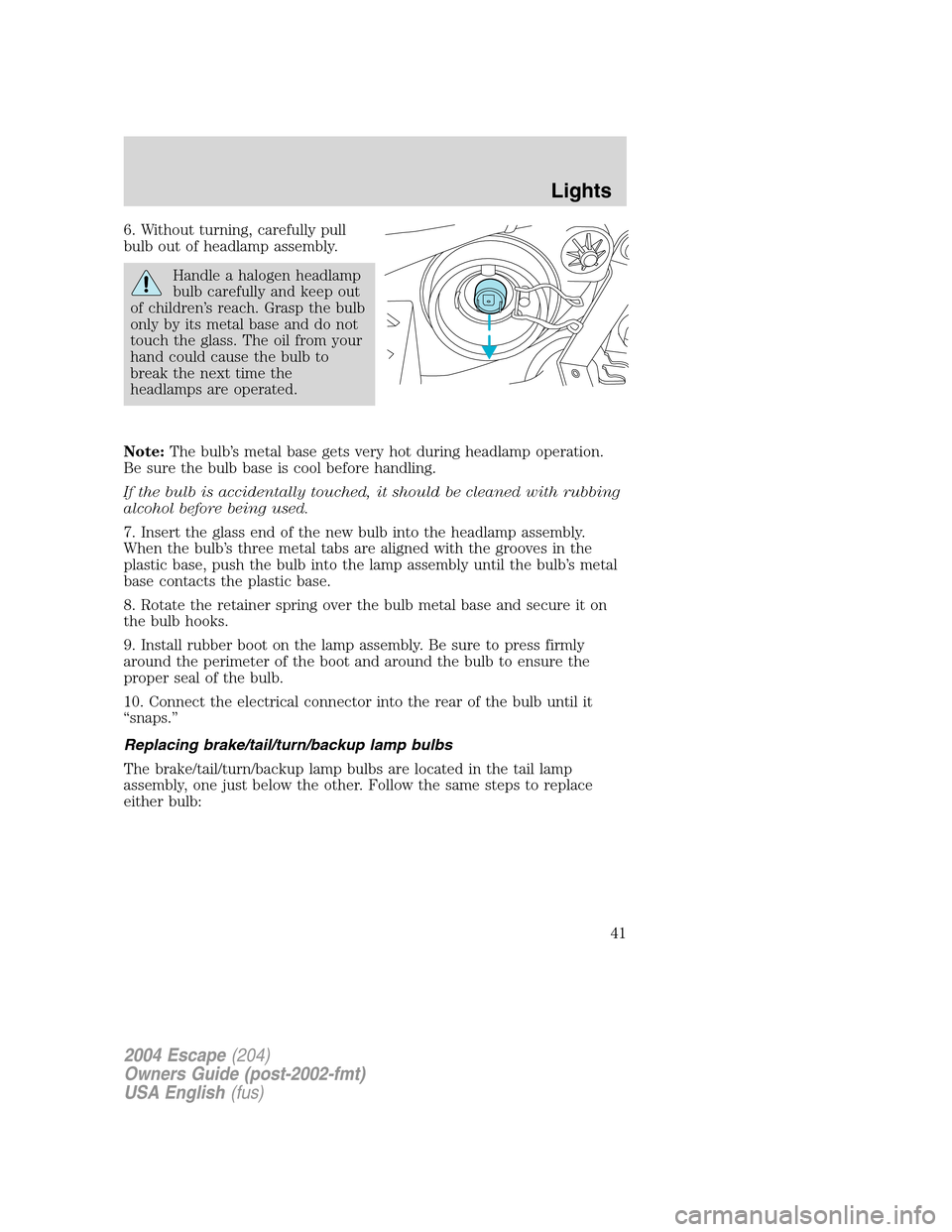
6. Without turning, carefully pull
bulb out of headlamp assembly.
Handle a halogen headlamp
bulb carefully and keep out
of children’s reach. Grasp the bulb
only by its metal base and do not
touch the glass. The oil from your
hand could cause the bulb to
break the next time the
headlamps are operated.
Note:The bulb’s metal base gets very hot during headlamp operation.
Be sure the bulb base is cool before handling.
If the bulb is accidentally touched, it should be cleaned with rubbing
alcohol before being used.
7. Insert the glass end of the new bulb into the headlamp assembly.
When the bulb’s three metal tabs are aligned with the grooves in the
plastic base, push the bulb into the lamp assembly until the bulb’s metal
base contacts the plastic base.
8. Rotate the retainer spring over the bulb metal base and secure it on
the bulb hooks.
9. Install rubber boot on the lamp assembly. Be sure to press firmly
around the perimeter of the boot and around the bulb to ensure the
proper seal of the bulb.
10. Connect the electrical connector into the rear of the bulb until it
“snaps.”
Replacing brake/tail/turn/backup lamp bulbs
The brake/tail/turn/backup lamp bulbs are located in the tail lamp
assembly, one just below the other. Follow the same steps to replace
either bulb:
2004 Escape(204)
Owners Guide (post-2002-fmt)
USA English(fus)
Lights
41
Page 85 of 240
Make sure that the seat is firmly locked into position and the
seat belt buckles are exposed.
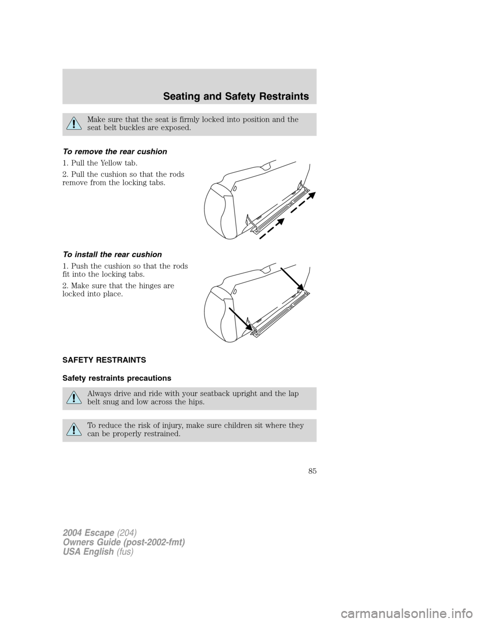
To remove the rear cushion
1. Pull the Yellow tab.
2. Pull the cushion so that the rods
remove from the locking tabs.
To install the rear cushion
1. Push the cushion so that the rods
fit into the locking tabs.
2. Make sure that the hinges are
locked into place.
SAFETY RESTRAINTS
Safety restraints precautions
Always drive and ride with your seatback upright and the lap
belt snug and low across the hips.
To reduce the risk of injury, make sure children sit where they
can be properly restrained.
2004 Escape(204)
Owners Guide (post-2002-fmt)
USA English(fus)
Seating and Safety Restraints
85
Page 119 of 240
Important ventilating information
If the engine is idling while the vehicle is stopped for a long period of
time, open the windows at least 2.5 cm (one inch) or adjust the heating
or air conditioning to bring in fresh air.
BRAKES
Occasional brake noise is normal. If a metal-to-metal, continuous grinding
or continuous squeal sound is present, the brake linings may be worn-out
and should be inspected by a qualified service technician. If the vehicle
has continuous vibration or shudder in the steering wheel while braking,
the vehicle should be inspected by a qualified service technician.
Under normal operating conditions, brake dust may accumulate on the
wheels. Some brake dust is inevitable as brakes wear and does not
contribute to brake noise. The use of modern friction materials with
emphasis on improved performance and environmental considerations
can lead to more dust than in the past. Brake dust can be cleaned by
weekly washing with soapy water and a soft sponge. Heavier deposits can
be removed with Motorcraft Wheel and Tire Cleaner (ZC-37–A).
Four-wheel anti-lock brake system (ABS) (if equipped)
Your vehicle may be equipped with an Anti-lock Braking System (ABS).
This system helps you maintain steering control during emergency stops
by keeping the brakes from locking. Noise from the ABS pump motor
and brake pedal pulsation may be observed during ABS braking; any
pulsation or mechanical noise you may feel or hear is normal.
Using ABS
When hard braking is required, apply continuous force on the brake
pedal; do not pump the brake pedal since this will reduce the
effectiveness of the ABS and will increase your vehicle’s stopping
distance. The ABS will be activated immediately, allowing you to retain
full steering control during hard braking and on slippery surfaces.
However, the ABS does not decrease stopping distance.
ABS warning lamp
ABS
TheABSlamp in the instrument cluster momentarily illuminates when
the ignition is turned to ON. If the light does not illuminate during start
up, remains on or flashes, the ABS may be disabled and may need to be
serviced
2004 Escape(204)
Owners Guide (post-2002-fmt)
USA English(fus)
Driving
119
Page 120 of 240
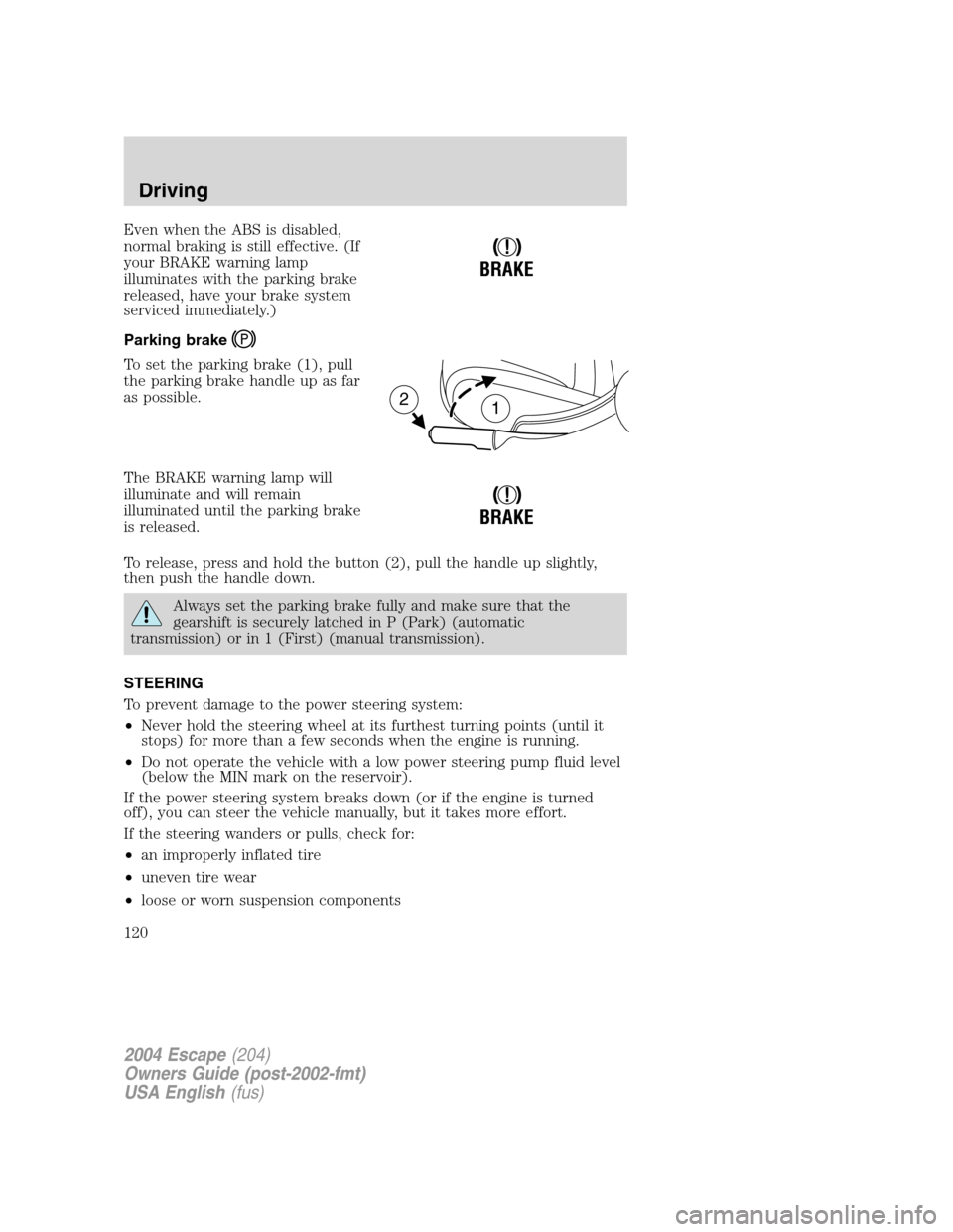
Even when the ABS is disabled,
normal braking is still effective. (If
your BRAKE warning lamp
illuminates with the parking brake
released, have your brake system
serviced immediately.)
Parking brake
To set the parking brake (1), pull
the parking brake handle up as far
as possible.
The BRAKE warning lamp will
illuminate and will remain
illuminated until the parking brake
is released.
To release, press and hold the button (2), pull the handle up slightly,
then push the handle down.
Always set the parking brake fully and make sure that the
gearshift is securely latched in P (Park) (automatic
transmission) or in 1 (First) (manual transmission).
STEERING
To prevent damage to the power steering system:
•Never hold the steering wheel at its furthest turning points (until it
stops) for more than a few seconds when the engine is running.
•Do not operate the vehicle with a low power steering pump fluid level
(below the MIN mark on the reservoir).
If the power steering system breaks down (or if the engine is turned
off), you can steer the vehicle manually, but it takes more effort.
If the steering wanders or pulls, check for:
•an improperly inflated tire
•uneven tire wear
•loose or worn suspension components
!
BRAKE
12
!
BRAKE
2004 Escape(204)
Owners Guide (post-2002-fmt)
USA English(fus)
Driving
120
Page 137 of 240

is equipped with a Four Wheel Anti-Lock Brake System (ABS), apply the
brake steadily. Do not “pump” the brakes. Refer to theBrakessection of
this chapter for additional information on the operation of the anti-lock
brake system.
Never drive with chains on the front tires of 4x4 vehicles without also
putting them on the rear tires. This could cause the rear to slide and
swing around during braking.
Tires, Replacement Requirements
Do not use a size and type of tire and wheel other than that
originally provided by Ford Motor Company because it can affect
the safety and performance of your vehicle, which could result in an
increased risk of loss of vehicle control, vehicle rollover, and/or serious
personal injury or death.
Do not use a size and type of tire and wheel other than that originally
provided by Ford Motor Company because it can affect the safety and
performance of your vehicle, which could lead to loss of vehicle control
or rollover and serious injury. Make sure all tires and wheels on the
vehicle are of the same size, type, tread design, brand and load-carrying
capacity. If you have questions regarding tire replacement, see an
authorized Ford or Lincoln/Mercury dealer.
If you nevertheless decide to equip your 4x4 for off-road use with tires
larger than what Ford Motor Company recommends, you should not use
these tires for highway driving.
If you use any tire/wheel combination not recommended by Ford Motor
Company, it may adversely affect vehicle handling and could cause
steering, suspension, axle or transfer case failure as well as the increased
risk of loss of vehicle control.
Do not use “aftermarket lift kits” or other suspension modifications,
whether or not they are used with larger tires and wheels.
These “aftermarket lift kits” could adversely affect the vehicle’s handling
characteristics, which could lead to loss of vehicle control or rollover and
serious injury.
Tires can be damaged during off-road use. For your safety, tires that are
damaged should not be used for highway driving because they are more
likely to blow out or fail.
2004 Escape(204)
Owners Guide (post-2002-fmt)
USA English(fus)
Driving
137
Page 153 of 240
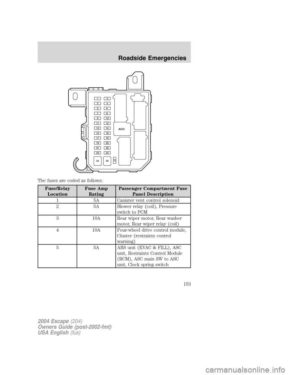
The fuses are coded as follows:
Fuse/Relay
LocationFuse Amp
RatingPassenger Compartment Fuse
Panel Description
1 5A Canister vent control solenoid
2 5A Blower relay (coil), Pressure
switch to PCM
3 10A Rear wiper motor, Rear washer
motor, Rear wiper relay (coil)
4 10A Four-wheel drive control module,
Cluster (restraints control
warning)
5 5A ABS unit (EVAC & FILL), ASC
unit, Restraints Control Module
(RCM), ASC main SW to ASC
unit, Clock spring switch
ACC
12
34
56
78
910
11 12
13 14
15 16
17 18
19 20
21 22
23 24
25 26
27
2004 Escape(204)
Owners Guide (post-2002-fmt)
USA English(fus)
Roadside Emergencies
153
Page 155 of 240
Fuse/Relay
LocationFuse Amp
RatingPassenger Compartment Fuse
Panel Description
22 15A Not used
23 20A Horn relay
24 15A Stoplamps, High mounted
stoplamp, Trailer stoplamp, ABS
unit, ASC unit (Brake Pedal
Position Switch), PCM, Shift
solenoid
25 30A Power window motors
26 30A Power door lock motors, GEM
(door lock relay coil), Power seat,
4WD relay
27 10A GEM, Audio, Cluster, Interior
lamp, Map lamp, Cargo lamp,
Datalink connector
ACC — Accessory relay
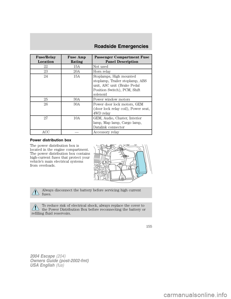
Power distribution box
The power distribution box is
located in the engine compartment.
The power distribution box contains
high-current fuses that protect your
vehicle’s main electrical systems
from overloads.
Always disconnect the battery before servicing high current
fuses.
To reduce risk of electrical shock, always replace the cover to
the Power Distribution Box before reconnecting the battery or
refilling fluid reservoirs.
2004 Escape(204)
Owners Guide (post-2002-fmt)
USA English(fus)
Roadside Emergencies
155
Page 156 of 240
If the battery has been disconnected and reconnected, refer to the
Batterysection of theMaintenance and specificationschapter.
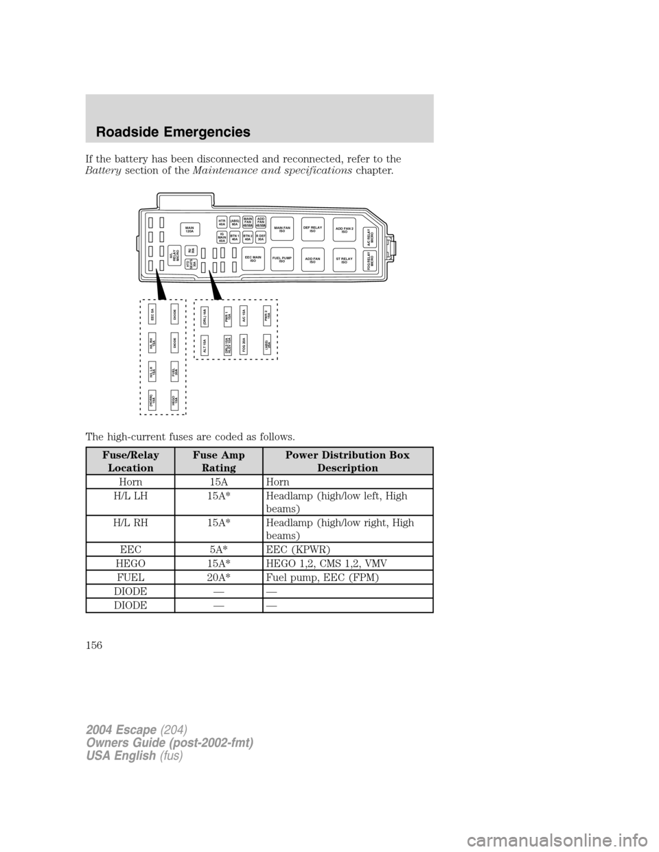
The high-current fuses are coded as follows.
Fuse/Relay
LocationFuse Amp
RatingPower Distribution Box
Description
Horn 15A Horn
H/L LH 15A* Headlamp (high/low left, High
beams)
H/L RH 15A* Headlamp (high/low right, High
beams)
EEC 5A* EEC (KPWR)
HEGO 15A* HEGO 1,2, CMS 1,2, VMV
FUEL 20A* Fuel pump, EEC (FPM)
DIODE — —
DIODE — —
MAIN
120A
HEGO
15A (HORN)
15A
FUEL
20ADIODE DIODE H/L LH
15AH/L RH
15AEEC 5A
INJ
30A
HTR
40A
BTN 1
40ABTN 240AR DEF30AIG
MAIN
40A
H/L
RELAY
MICRO
MAIN
FAN(ABS)
60A
ST RELAY
ISO DEF RELAY
ISOADD FAN 2
ISO
A/C RELAY
MICRO FOG RELAY
MICRO
MAIN FAN
ISO
ADD FAN
ISO EEC MAIN
ISOFUEL PUMP
ISO
ALT 15A
FOG 20A(DRL) 15A
PWR 1
15A DRL2 15A
HLEV 10A
(ABS)
25APWR 2
15A A/C 15A
40/50AADD
FAN
40/50A
HTD
SEATS
30A
2004 Escape(204)
Owners Guide (post-2002-fmt)
USA English(fus)
Roadside Emergencies
156