display FORD ESCAPE 2019 Manual PDF
[x] Cancel search | Manufacturer: FORD, Model Year: 2019, Model line: ESCAPE, Model: FORD ESCAPE 2019Pages: 509, PDF Size: 6.69 MB
Page 201 of 509
Note:
The system may not alert you if a
vehicle quickly passes through the detection
zone.
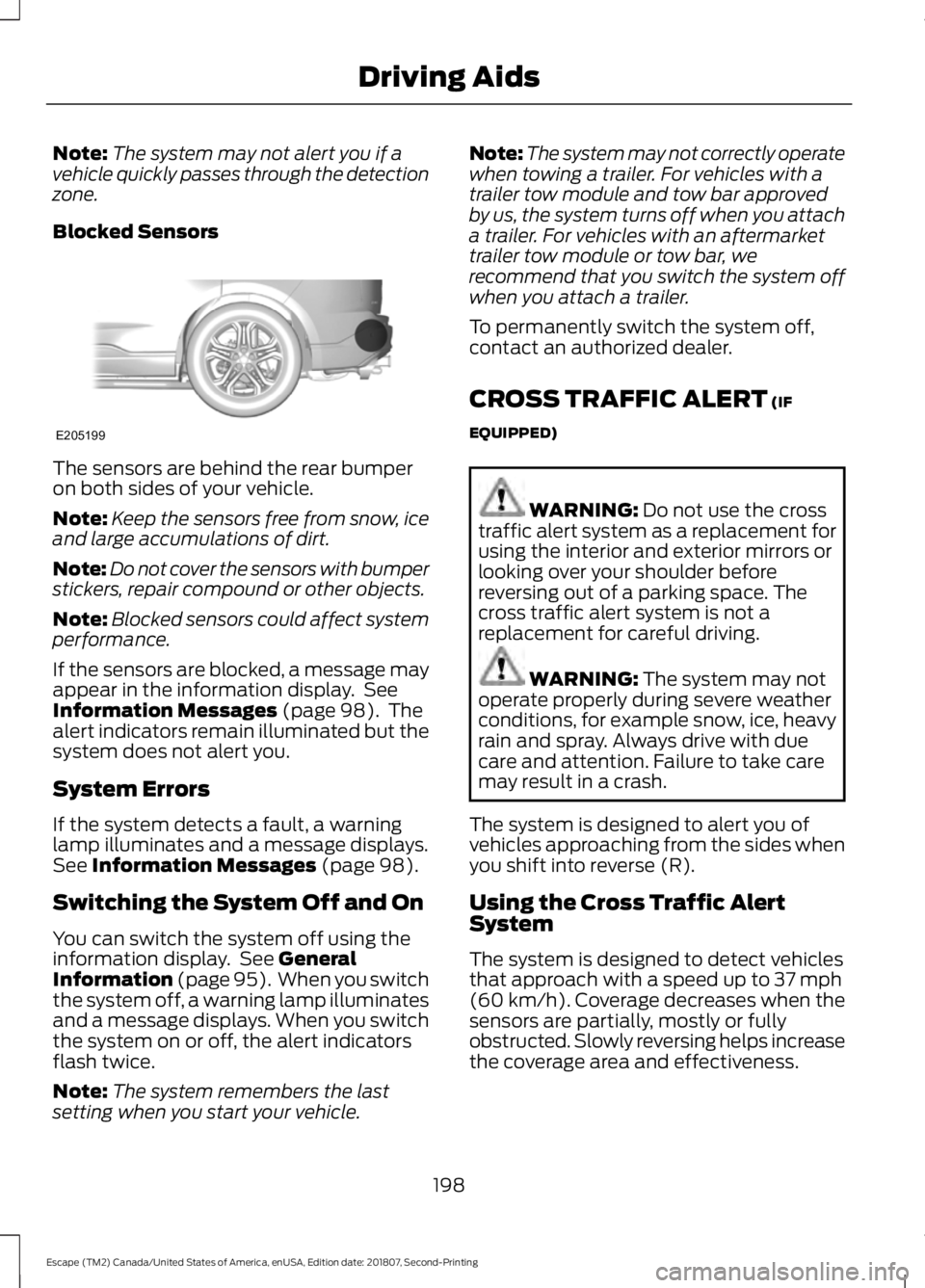
Blocked Sensors The sensors are behind the rear bumper
on both sides of your vehicle.
Note:
Keep the sensors free from snow, ice
and large accumulations of dirt.
Note: Do not cover the sensors with bumper
stickers, repair compound or other objects.
Note: Blocked sensors could affect system
performance.
If the sensors are blocked, a message may
appear in the information display. See
Information Messages (page 98). The
alert indicators remain illuminated but the
system does not alert you.
System Errors
If the system detects a fault, a warning
lamp illuminates and a message displays.
See
Information Messages (page 98).
Switching the System Off and On
You can switch the system off using the
information display. See
General
Information (page 95). When you switch
the system off, a warning lamp illuminates
and a message displays. When you switch
the system on or off, the alert indicators
flash twice.
Note: The system remembers the last
setting when you start your vehicle. Note:
The system may not correctly operate
when towing a trailer. For vehicles with a
trailer tow module and tow bar approved
by us, the system turns off when you attach
a trailer. For vehicles with an aftermarket
trailer tow module or tow bar, we
recommend that you switch the system off
when you attach a trailer.
To permanently switch the system off,
contact an authorized dealer.
CROSS TRAFFIC ALERT
(IF
EQUIPPED) WARNING:
Do not use the cross
traffic alert system as a replacement for
using the interior and exterior mirrors or
looking over your shoulder before
reversing out of a parking space. The
cross traffic alert system is not a
replacement for careful driving. WARNING:
The system may not
operate properly during severe weather
conditions, for example snow, ice, heavy
rain and spray. Always drive with due
care and attention. Failure to take care
may result in a crash.
The system is designed to alert you of
vehicles approaching from the sides when
you shift into reverse (R).
Using the Cross Traffic Alert
System
The system is designed to detect vehicles
that approach with a speed up to
37 mph
(60 km/h). Coverage decreases when the
sensors are partially, mostly or fully
obstructed. Slowly reversing helps increase
the coverage area and effectiveness.
198
Escape (TM2) Canada/United States of America, enUSA, Edition date: 201807, Second-Printing Driving AidsE205199
Page 203 of 509
Zone coverage also decreases when
parking at narrow angles. The sensor on
the left-hand side is mostly obstructed and
zone coverage on that side is severely
reduced.
System Lights, Messages and
Audible Alerts
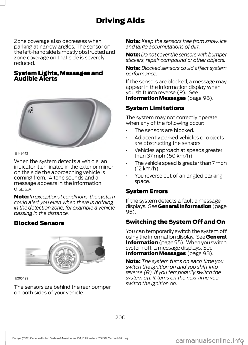
When the system detects a vehicle, an
indicator illuminates in the exterior mirror
on the side the approaching vehicle is
coming from. A tone sounds and a
message appears in the information
display.
Note:
In exceptional conditions, the system
could alert you even when there is nothing
in the detection zone, for example a vehicle
passing in the distance.
Blocked Sensors The sensors are behind the rear bumper
on both sides of your vehicle. Note:
Keep the sensors free from snow, ice
and large accumulations of dirt.
Note: Do not cover the sensors with bumper
stickers, repair compound or other objects.
Note: Blocked sensors could affect system
performance.
If the sensors are blocked, a message may
appear in the information display when
you shift into reverse (R). See
Information Messages (page 98).
System Limitations
The system may not correctly operate
when any of the following occur:
• The sensors are blocked.
• Adjacently parked vehicles or objects
are obstructing the sensors.
• Vehicles approach at speeds greater
than
37 mph (60 km/h).
• The vehicle speed is greater than 7 mph
(12 km/h)
.
• You reverse out of an angled parking
space.
System Errors
If the system detects a fault a message
displays. See General Information (page
95
).
Switching the System Off and On
You can temporarily switch the system off
using the information display. See
General
Information (page 95). When you switch
system off, a message displays. See
Information Messages (page 98).
Note: The system turns on each time you
switch the ignition on and you shift into
reverse (R). If you temporarily switch the
system off, it turns on the next time you
switch the ignition on.
200
Escape (TM2) Canada/United States of America, enUSA, Edition date: 201807, Second-Printing Driving AidsE142442 E205199
Page 204 of 509
Note:
The system may not correctly operate
when towing a trailer. For vehicles with a
trailer tow module and tow bar approved
by us, the system turns off when you attach
a trailer. For vehicles with an aftermarket
trailer tow module or tow bar, we
recommend that you switch the system off
when you attach a trailer.
To permanently switch the system off,
contact an authorized dealer.
STEERING
Electric Power Steering WARNING: The electric power
steering system has diagnostic checks
that continuously monitor the system. If
a fault is detected, a message displays
in the information display. Stop your
vehicle as soon as it is safe to do so.
Switch the ignition off. After at least 10
seconds, switch the ignition on and
watch the information display for a
steering system warning message. If a
steering system warning message
returns, have the system checked as
soon as possible. WARNING:
If the system detects
an error, you may not feel a difference in
the steering, however a serious condition
may exist. Have your vehicle checked as
soon as possible. Failure to do so may
result in loss of steering control.
Your vehicle is equipped with an electric
power-assisted steering system. There is
no fluid reservoir to check or fill.
If your vehicle loses electrical power while
you are driving (or if the ignition is turned
off), you can steer the vehicle manually,
but it takes more effort. Extreme
continuous steering may increase the effort
it takes for you to steer. This occurs to prevent internal overheating and
permanent damage to your steering
system. If this should occur, you will neither
lose the ability to steer the vehicle
manually nor will it cause permanent
damage. Typical steering and driving
maneuvers will allow the system to cool
down and steering assist will return to
normal.
Steering Tips
If the steering wanders or pulls, check for:
•
An improperly inflated tire.
• Uneven tire wear.
• Loose or worn suspension
components.
• Loose or worn steering components.
• Improper vehicle alignment.
A high crown in the road or high crosswinds
may also make the steering seem to
wander or pull.
COLLISION WARNING SYSTEM
(IF EQUIPPED)
PRINCIPLE OF OPERATION WARNING: This system is
designed to be a supplementary driving
aid. It is not intended to replace the
driver ’s attention, and judgment, or the
need to apply the brakes. This system
does NOT activate the brakes
automatically. Failure to press the brake
pedal to activate the brakes may result
in a collision.
201
Escape (TM2) Canada/United States of America, enUSA, Edition date: 201807, Second-Printing Driving Aids
Page 205 of 509
WARNING: The collision warning
system with brake support cannot help
prevent all collisions. Do not rely on this
system to replace driver judgment and
the need to maintain distance and
speed.
Note: The system does not detect, warn or
respond to potential collisions with vehicles
to the rear or sides of the vehicle.
Note: The collision warning system is active
at speeds above approximately
5 mph
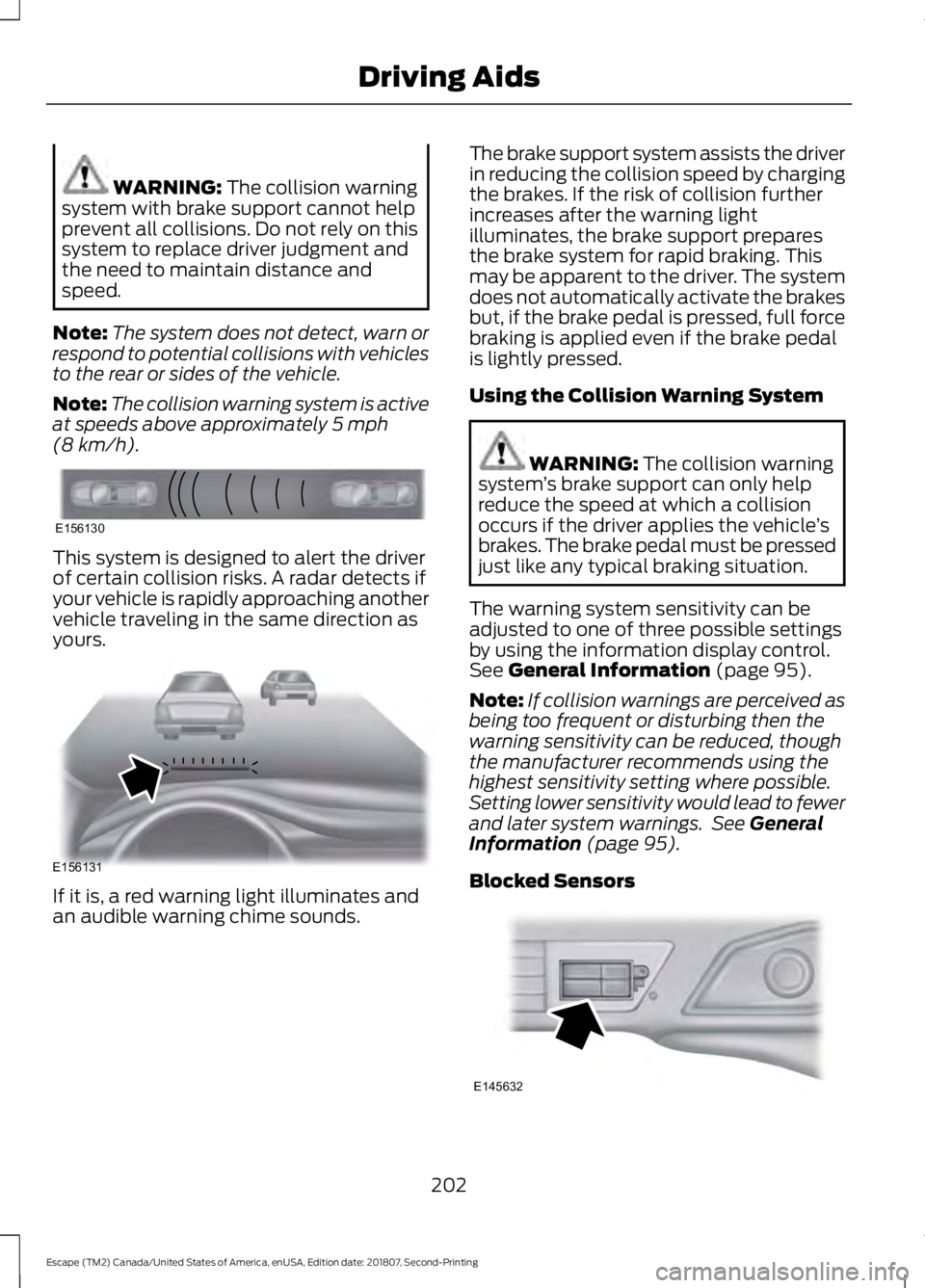
(8 km/h). This system is designed to alert the driver
of certain collision risks. A radar detects if
your vehicle is rapidly approaching another
vehicle traveling in the same direction as
yours.
If it is, a red warning light illuminates and
an audible warning chime sounds. The brake support system assists the driver
in reducing the collision speed by charging
the brakes. If the risk of collision further
increases after the warning light
illuminates, the brake support prepares
the brake system for rapid braking. This
may be apparent to the driver. The system
does not automatically activate the brakes
but, if the brake pedal is pressed, full force
braking is applied even if the brake pedal
is lightly pressed.
Using the Collision Warning System WARNING: The collision warning
system ’s brake support can only help
reduce the speed at which a collision
occurs if the driver applies the vehicle ’s
brakes. The brake pedal must be pressed
just like any typical braking situation.
The warning system sensitivity can be
adjusted to one of three possible settings
by using the information display control.
See
General Information (page 95).
Note: If collision warnings are perceived as
being too frequent or disturbing then the
warning sensitivity can be reduced, though
the manufacturer recommends using the
highest sensitivity setting where possible.
Setting lower sensitivity would lead to fewer
and later system warnings. See
General
Information (page 95).
Blocked Sensors 202
Escape (TM2) Canada/United States of America, enUSA, Edition date: 201807, Second-Printing Driving AidsE156130 E156131 E145632
Page 206 of 509
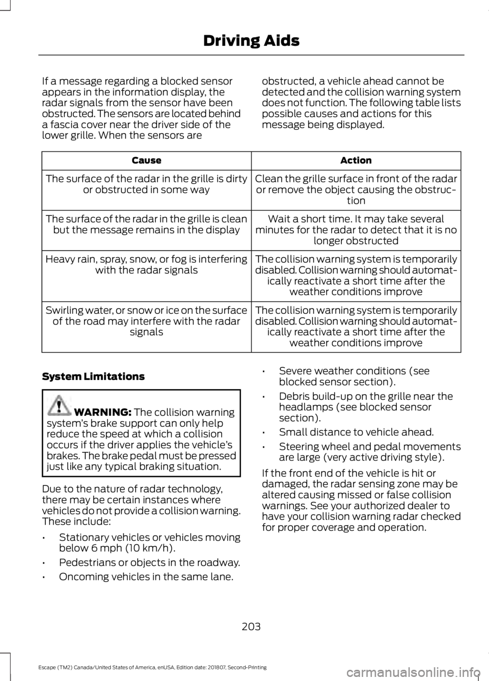
If a message regarding a blocked sensor
appears in the information display, the
radar signals from the sensor have been
obstructed. The sensors are located behind
a fascia cover near the driver side of the
lower grille. When the sensors are
obstructed, a vehicle ahead cannot be
detected and the collision warning system
does not function. The following table lists
possible causes and actions for this
message being displayed. Action
Cause
Clean the grille surface in front of the radaror remove the object causing the obstruc- tion
The surface of the radar in the grille is dirty
or obstructed in some way
Wait a short time. It may take several
minutes for the radar to detect that it is no longer obstructed
The surface of the radar in the grille is clean
but the message remains in the display
The collision warning system is temporarily
disabled. Collision warning should automat-ically reactivate a short time after the weather conditions improve
Heavy rain, spray, snow, or fog is interfering
with the radar signals
The collision warning system is temporarily
disabled. Collision warning should automat-ically reactivate a short time after the weather conditions improve
Swirling water, or snow or ice on the surface
of the road may interfere with the radar signals
System Limitations WARNING: The collision warning
system ’s brake support can only help
reduce the speed at which a collision
occurs if the driver applies the vehicle ’s
brakes. The brake pedal must be pressed
just like any typical braking situation.
Due to the nature of radar technology,
there may be certain instances where
vehicles do not provide a collision warning.
These include:
• Stationary vehicles or vehicles moving
below 6 mph (10 km/h).
• Pedestrians or objects in the roadway.
• Oncoming vehicles in the same lane. •
Severe weather conditions (see
blocked sensor section).
• Debris build-up on the grille near the
headlamps (see blocked sensor
section).
• Small distance to vehicle ahead.
• Steering wheel and pedal movements
are large (very active driving style).
If the front end of the vehicle is hit or
damaged, the radar sensing zone may be
altered causing missed or false collision
warnings. See your authorized dealer to
have your collision warning radar checked
for proper coverage and operation.
203
Escape (TM2) Canada/United States of America, enUSA, Edition date: 201807, Second-Printing Driving Aids
Page 215 of 509
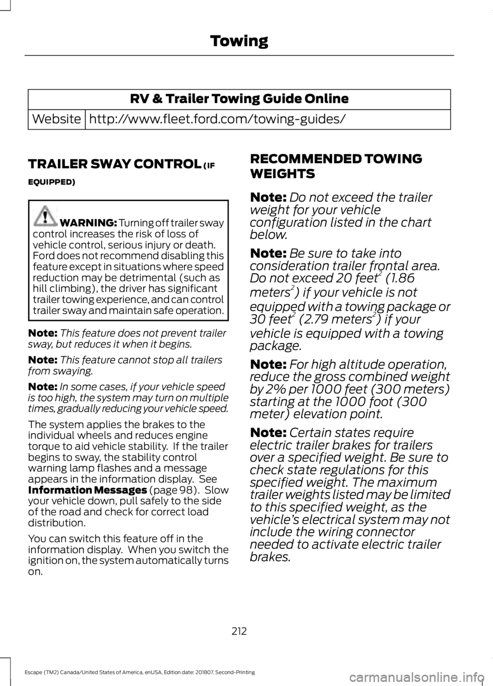
RV & Trailer Towing Guide Online
http://www.fleet.ford.com/towing-guides/
Website
TRAILER SWAY CONTROL (IF
EQUIPPED) WARNING: Turning off trailer sway
control increases the risk of loss of
vehicle control, serious injury or death.
Ford does not recommend disabling this
feature except in situations where speed
reduction may be detrimental (such as
hill climbing), the driver has significant
trailer towing experience, and can control
trailer sway and maintain safe operation.
Note: This feature does not prevent trailer
sway, but reduces it when it begins.
Note: This feature cannot stop all trailers
from swaying.
Note: In some cases, if your vehicle speed
is too high, the system may turn on multiple
times, gradually reducing your vehicle speed.
The system applies the brakes to the
individual wheels and reduces engine
torque to aid vehicle stability. If the trailer
begins to sway, the stability control
warning lamp flashes and a message
appears in the information display. See
Information Messages
(page 98). Slow
your vehicle down, pull safely to the side
of the road and check for correct load
distribution.
You can switch this feature off in the
information display. When you switch the
ignition on, the system automatically turns
on. RECOMMENDED TOWING
WEIGHTS
Note:
Do not exceed the trailer
weight for your vehicle
configuration listed in the chart
below.
Note: Be sure to take into
consideration trailer frontal area.
Do not exceed 20 feet 2
(1.86
meters 2
) if your vehicle is not
equipped with a towing package or
30 feet 2
(2.79 meters 2
) if your
vehicle is equipped with a towing
package.
Note: For high altitude operation,
reduce the gross combined weight
by 2% per 1000 feet (300 meters)
starting at the 1000 foot (300
meter) elevation point.
Note: Certain states require
electric trailer brakes for trailers
over a specified weight. Be sure to
check state regulations for this
specified weight. The maximum
trailer weights listed may be limited
to this specified weight, as the
vehicle ’s electrical system may not
include the wiring connector
needed to activate electric trailer
brakes.
212
Escape (TM2) Canada/United States of America, enUSA, Edition date: 201807, Second-Printing Towing
Page 241 of 509
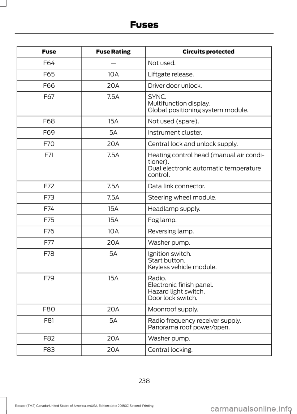
Circuits protected
Fuse Rating
Fuse
Not used.
—
F64
Liftgate release.
10A
F65
Driver door unlock.
20A
F66
SYNC.
7.5A
F67
Multifunction display.
Global positioning system module.
Not used (spare).
15A
F68
Instrument cluster.
5A
F69
Central lock and unlock supply.
20A
F70
Heating control head (manual air condi-
tioner).
7.5A
F71
Dual electronic automatic temperature
control.
Data link connector.
7.5A
F72
Steering wheel module.
7.5A
F73
Headlamp supply.
15A
F74
Fog lamp.
15A
F75
Reversing lamp.
10A
F76
Washer pump.
20A
F77
Ignition switch.
5A
F78
Start button.
Keyless vehicle module.
Radio.
15A
F79
Electronic finish panel.
Hazard light switch.
Door lock switch.
Moonroof supply.
20A
F80
Radio frequency receiver supply.
5A
F81
Panorama roof power/open.
Washer pump.
20A
F82
Central locking.
20A
F83
238
Escape (TM2) Canada/United States of America, enUSA, Edition date: 201807, Second-Printing Fuses
Page 253 of 509
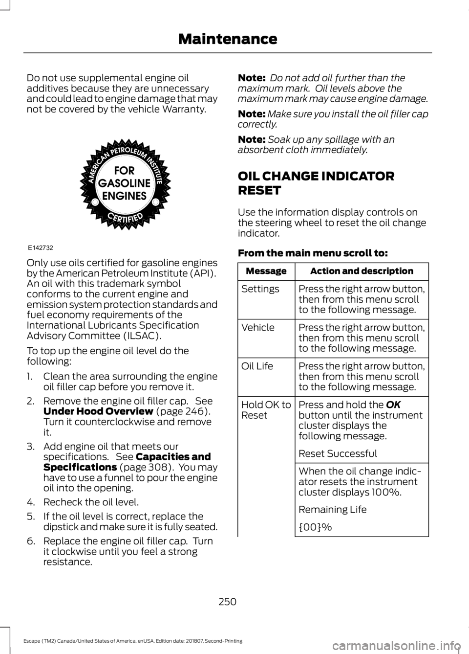
Do not use supplemental engine oil
additives because they are unnecessary
and could lead to engine damage that may
not be covered by the vehicle Warranty.
Only use oils certified for gasoline engines
by the American Petroleum Institute (API).
An oil with this trademark symbol
conforms to the current engine and
emission system protection standards and
fuel economy requirements of the
International Lubricants Specification
Advisory Committee (ILSAC).
To top up the engine oil level do the
following:
1. Clean the area surrounding the engine
oil filler cap before you remove it.
2. Remove the engine oil filler cap. See Under Hood Overview (page 246).
Turn it counterclockwise and remove
it.
3. Add engine oil that meets our specifications. See
Capacities and
Specifications (page 308). You may
have to use a funnel to pour the engine
oil into the opening.
4. Recheck the oil level.
5. If the oil level is correct, replace the dipstick and make sure it is fully seated.
6. Replace the engine oil filler cap. Turn it clockwise until you feel a strong
resistance. Note:
Do not add oil further than the
maximum mark. Oil levels above the
maximum mark may cause engine damage.
Note: Make sure you install the oil filler cap
correctly.
Note: Soak up any spillage with an
absorbent cloth immediately.
OIL CHANGE INDICATOR
RESET
Use the information display controls on
the steering wheel to reset the oil change
indicator.
From the main menu scroll to: Action and description
Message
Press the right arrow button,
then from this menu scroll
to the following message.
Settings
Press the right arrow button,
then from this menu scroll
to the following message.
Vehicle
Press the right arrow button,
then from this menu scroll
to the following message.
Oil Life
Press and hold the
OK
button until the instrument
cluster displays the
following message.
Hold OK to
Reset
Reset Successful
When the oil change indic-
ator resets the instrument
cluster displays 100%.
Remaining Life
{00}%
250
Escape (TM2) Canada/United States of America, enUSA, Edition date: 201807, Second-Printing MaintenanceE142732
Page 254 of 509
Action and description
Message
If the instrument cluster
displays one of the following
messages, repeat the
process.
Not Reset
Reset Cancelled
ENGINE COOLANT CHECK WARNING: Do not remove the
coolant reservoir cap when the engine is
on or the cooling system is hot. Wait 10
minutes for the cooling system to cool
down. Cover the coolant reservoir cap
with a thick cloth to prevent the
possibility of scalding and slowly remove
the cap. Failure to follow this instruction
could result in personal injury. WARNING:
Do not put coolant in
the windshield washer reservoir. If
sprayed on the windshield, coolant could
make it difficult to see through the
windshield. WARNING:
To reduce the risk of
personal injury, make sure the engine is
cool before unscrewing the coolant
pressure relief cap. The cooling system
is under pressure. Steam and hot liquid
can come out forcefully when you loosen
the cap slightly. WARNING:
Do not add coolant
further than the MAX mark.
When the engine is cold, check the
concentration and level of the coolant at
the intervals listed in the scheduled
maintenance information. See Scheduled
Maintenance
(page 448). Note:
Make sure that the coolant level is
between the
MIN and MAX marks on the
coolant reservoir.
Note: Coolant expands when it is hot. The
level may extend beyond the
MAX mark.
Maintain coolant concentration within
48% to 50%, which equates to a freeze
point between
-29°F (-34°C) and -35°F
(-37°C). Coolant concentration should be
checked using a refractometer. We do not
recommend the use of hydrometers or
coolant test strips for measuring coolant
concentration.
Adding Coolant WARNING:
Do not add engine
coolant when the engine is hot. Failure
to follow this instruction could result in
personal injury. WARNING:
Do not remove the
coolant reservoir cap when the engine is
on or the cooling system is hot. Wait 10
minutes for the cooling system to cool
down. Cover the coolant reservoir cap
with a thick cloth to prevent the
possibility of scalding and slowly remove
the cap. Failure to follow this instruction
could result in personal injury. WARNING:
Do not put coolant in
the windshield washer reservoir. If
sprayed on the windshield, coolant could
make it difficult to see through the
windshield.
Note: Do not use stop leak pellets, cooling
system sealants, or non-specified additives
as they can cause damage to the engine
cooling or heating systems. Resulting
component damage may not be covered by
the vehicle Warranty.
Note: Automotive fluids are not
interchangeable.
251
Escape (TM2) Canada/United States of America, enUSA, Edition date: 201807, Second-Printing Maintenance
Page 256 of 509
Follow your community's regulations and
standards for recycling and disposing of
automotive fluids.
Severe Climates
If you drive in extremely cold climates:
•
It may be necessary to increase the
coolant concentration above 50%.
• A coolant concentration of 60%
provides improved freeze point
protection. Coolant concentrations
above 60% decrease the overheat
protection characteristics of the
coolant and may cause engine
damage.
If you drive in extremely hot climates:
• You can decrease the coolant
concentration to 40%.
• Coolant concentrations below 40%
decrease the freeze and corrosion
protection characteristics of the
coolant and may cause engine
damage.
Vehicles driven year-round in non-extreme
climates should use prediluted coolant for
optimum cooling system and engine
protection.
Coolant Change
At specific mileage intervals, as listed in
the scheduled maintenance information,
the coolant should be changed. Add
prediluted coolant approved to the correct
specification. See Capacities and
Specifications (page 301).
Fail-Safe Cooling
Fail-safe cooling allows you to temporarily
drive your vehicle before any incremental
component damage occurs. The fail-safe
distance depends on ambient
temperature, vehicle load and terrain. How Fail-Safe Cooling Works If the engine begins to overheat,
the coolant temperature gauge
moves toward the red zone:
A warning lamp illuminates and
a message may appear in the
information display.
If the engine reaches a preset
over-temperature condition, the engine
automatically switches to alternating
cylinder operation. Each disabled cylinder
acts as an air pump and cools the engine.
When this occurs, your vehicle still
operates, however:
• Engine power is limited.
• The air conditioning system turns off.
Continued operation increases the engine
temperature, causing the engine to
completely shut down. Your steering and
braking effort increases in this situation.
When the engine temperature cools, you
can re-start the engine. Have your vehicle
checked as soon as possible to minimize
engine damage.
When Fail-Safe Mode Is Activated WARNING:
Fail-safe mode is for
use during emergencies only. Operate
your vehicle in fail-safe mode only as
long as necessary to bring your vehicle
to rest in a safe location and seek
immediate repairs. When in fail-safe
mode, your vehicle will have limited
power, will not be able to maintain
high-speed operation, and may
completely shut down without warning,
potentially losing engine power, power
steering assist, and power brake assist,
which may increase the possibility of a
crash resulting in serious injury.
253
Escape (TM2) Canada/United States of America, enUSA, Edition date: 201807, Second-Printing Maintenance