service indicator FORD ESCAPE 2020 User Guide
[x] Cancel search | Manufacturer: FORD, Model Year: 2020, Model line: ESCAPE, Model: FORD ESCAPE 2020Pages: 553, PDF Size: 7.73 MB
Page 203 of 553
What to Do
What it Means
Convenience Cord LED
Indicators
Check
Outlet
(Amber)
Fault
(Red)
Power
(Green)
Request vehicleservice.
The convenience cord is experiencing a
ground fault at the charge port. The
cordset retry mode has been exhausted. Your vehicle is not charging. Call for service.
Off
On
On
Connect to a prop-erly grounded AC outlet.
Missing ground at AC outlet. Your
vehicle is not charging. The convenience cord is in retry mode.
Two
flash
interval
On/Two
flash
interval
On
Request cordsetservice. Replace the cordset.
The convenience cord is experiencing
an internal fault. Call for service.
Off
On/
Flashing
On
Note: If charging for your plug-in vehicle
fails, please call the Customer Relationship
Center, or click on Call for support or Live
chat at our website.
Charge Port
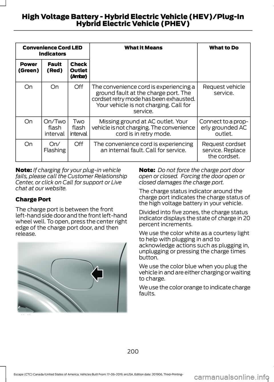
The charge port is between the front
left-hand side door and the front left-hand
wheel well. To open, press the center right
edge of the charge port door, and then
release. Note:
Do not force the charge port door
open or closed. Forcing the door open or
closed damages the charge port.
The charge status indicator around the
charge port indicates the charge status of
the high voltage battery in your vehicle.
Divided into five zones, the charge status
indicator displays the state of charge in 20
percent increments.
We use the color white as a courtesy light
to help with plugging in and to
acknowledge actions such as plugging in,
unplugging or pressing the charge times
button.
We use the color blue when you plug the
vehicle in and are either charging or waiting
to charge.
We use the color orange to indicate charge
faults.
200
Escape (CTC) Canada/United States of America, Vehicles Built From: 17-06-2019, enUSA, Edition date: 201906, Third-Printing- High Voltage Battery - Hybrid Electric Vehicle (HEV)/Plug-In
Hybrid Electric Vehicle (PHEV)E295258
Page 225 of 553
PRINCIPLE OF OPERATION
The traction control system helps avoid
drive wheel spin and loss of traction.
If your vehicle begins to slide, the system
applies the brakes to individual wheels
and, when needed, reduces engine power
at the same time. If the wheels spin when
accelerating on slippery or loose surfaces,
the system reduces engine power in order
to increase traction.
USING TRACTION CONTROL
WARNING: The stability and
traction control light illuminates steadily
if the system detects a failure. Make sure
you did not manually disable the traction
control system using the information
display controls or the switch. If the
stability control and traction control light
is still illuminating steadily, have the
system serviced by an authorized dealer
immediately. Operating your vehicle with
the traction control disabled could lead
to an increased risk of loss of vehicle
control, vehicle rollover, personal injury
and death.
The system automatically turns on each
time you switch the ignition on.
If your vehicle is stuck in mud or snow,
switching traction control off may be
beneficial as this allows the wheels to spin.
Note: When you switch traction control off,
stability control remains fully active.
Switching the System Off
When you switch the system off or on, a
message appears in the information
display showing system status. You can switch the system off by either
using the information display controls or
the switch.
Using the Information Display
Controls
You can switch this feature off or on in the
information display.
See General
Information (page 110).
Using a Switch
(If Equipped)
Use the traction control switch on the
instrument panel to switch the system off
or on.
System Indicator Lights and
Messages The stability and traction control
light:
• Temporarily illuminates on engine
start-up.
• Flashes when a driving condition
activates either of the systems.
• Illuminates if a problem occurs in either
of the systems. The stability and traction control
off light temporarily illuminates
on engine start-up and stays on
when you switch the traction control
system off.
222
Escape (CTC) Canada/United States of America, Vehicles Built From: 17-06-2019, enUSA, Edition date: 201906, Third-Printing- Traction ControlE138639 E130458
Page 282 of 553
ESSENTIAL TOWING CHECKS
Follow these guidelines for safe towing:
•
Do not tow a trailer until you drive your
vehicle at least 1,000 mi (1,600 km).
• Consult your local motor vehicle laws
for towing a trailer.
• See the instructions included with
towing accessories for the proper
installation and adjustment
specifications.
• Service your vehicle more frequently if
you tow a trailer. See your scheduled
maintenance information.
• If you use a rental trailer, follow the
instructions the rental agency gives
you.
You can find information on load
specification terms found on the tire label
and Safety Compliance label as well as
instructions on calculating your vehicle's
load in the Load Carrying chapter. See
Load Limit
(page 270).
Remember to account for the trailer
tongue weight as part of your vehicle load
when calculating the total vehicle weight.
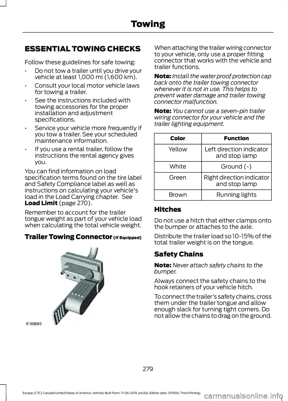
Trailer Towing Connector
(If Equipped) When attaching the trailer wiring connector
to your vehicle, only use a proper fitting
connector that works with the vehicle and
trailer functions.
Note:
Install the water proof protection cap
back onto the trailer towing connector
whenever it is not in use. This helps to
prevent water damage and trailer towing
connector malfunction.
Note: You cannot use a seven-pin trailer
wiring connector for your vehicle and the
trailer lighting equipment. Function
Color
Left direction indicatorand stop lamp
Yellow
Ground (-)
White
Right direction indicatorand stop lamp
Green
Running lights
Brown
Hitches
Do not use a hitch that either clamps onto
the bumper or attaches to the axle.
Distribute the trailer load so 10-15% of the
total trailer weight is on the tongue.
Safety Chains
Note: Never attach safety chains to the
bumper.
Always connect the safety chains to the
hook retainers of your vehicle hitch.
To connect the trailer ’s safety chains, cross
them under the trailer tongue and allow
enough slack for turning tight corners. Do
not allow the chains to drag on the ground.
279
Escape (CTC) Canada/United States of America, Vehicles Built From: 17-06-2019, enUSA, Edition date: 201906, Third-Printing- TowingE168683
Page 291 of 553
Vehicles Sold in Canada: Getting
Roadside Assistance
To fully assist you should you have a
vehicle concern, Ford Motor Company of
Canada, Limited offers a complimentary
roadside assistance program. This program
is eligible within Canada or the continental
United States.
The service is available 24 hours a day,
seven days a week.
This program is separate from the New
Vehicle Limited Warranty, but the coverage
is concurrent with the powertrain coverage
period of your vehicle. Canadian roadside
coverage and benefits may differ from the
U.S. coverage.
If you require more information, please call
us in Canada at 1-800-665-2006, or visit
our website at www.ford.ca.
HAZARD FLASHERS
Note:
The hazard flashers operate when
the ignition is in any position, or if the key is
not in the ignition. If used when the vehicle
is not running, the battery loses charge. As
a result, there may be insufficient power to
restart your vehicle. The flasher control is on the
instrument panel. Use your
hazard flashers when your
vehicle is creating a safety hazard for other
motorists.
• Press the flasher control and all front
and rear direction indicators flash.
• Press the button again to switch them
off. FUEL SHUTOFF WARNING: If your vehicle has been
involved in a crash, have the fuel system
checked. Failure to follow this instruction
could result in fire, personal injury or
death.
Note: When you try to restart your vehicle
after a fuel shutoff, the vehicle makes sure
that various systems are safe to restart.
Once the vehicle determines the systems
are safe, then the vehicle allows you to
restart.
Note: In the event that your vehicle does
not restart after your third attempt, contact
a qualified technician.
The fuel pump shutoff stops the flow of
fuel to the engine in the event of a
moderate to severe crash. Not every
impact causes a shutoff.
Should your vehicle shut off after a crash,
you may restart your vehicle.
If your vehicle has a key system:
1. Switch off the ignition.
2. Switch to start position.
3. Switch off the ignition.
4. Switch on the ignition to re-enable the
fuel pump.
5. If the vehicle does not start, repeat steps 1 through 4.
If your vehicle has a push button start
system:
1. Press START/STOP to switch off your
vehicle.
2. Press the brake pedal and START/STOP
to switch on your
vehicle.
3. Remove your foot from the brake pedal
and press
START/STOP to switch off
your vehicle.
288
Escape (CTC) Canada/United States of America, Vehicles Built From: 17-06-2019, enUSA, Edition date: 201906, Third-Printing- Roadside Emergencies
Page 336 of 553
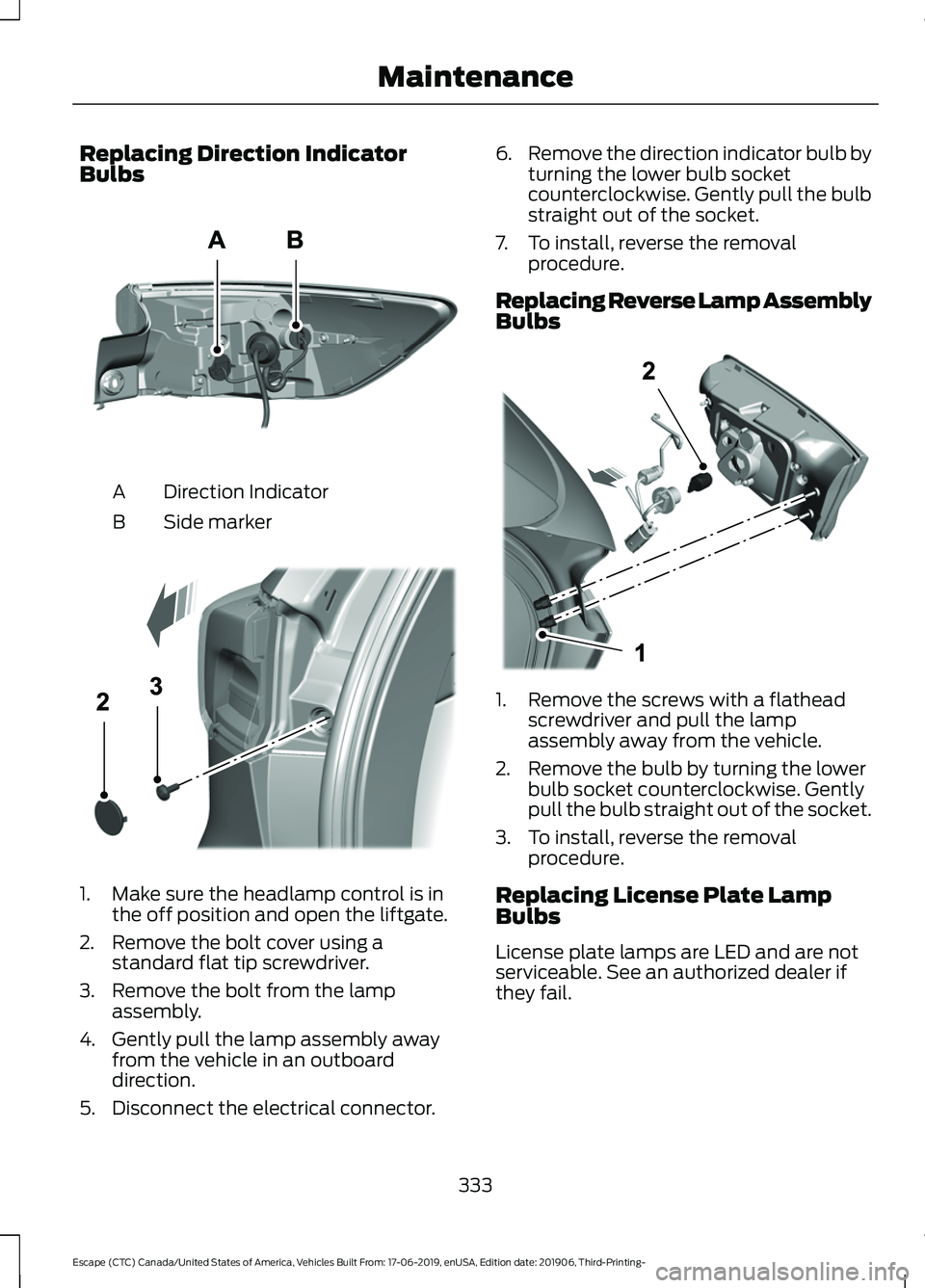
Replacing Direction Indicator
Bulbs
Direction Indicator
A
Side marker
B 1. Make sure the headlamp control is in
the off position and open the liftgate.
2. Remove the bolt cover using a standard flat tip screwdriver.
3. Remove the bolt from the lamp assembly.
4. Gently pull the lamp assembly away from the vehicle in an outboard
direction.
5. Disconnect the electrical connector. 6.
Remove the direction indicator bulb by
turning the lower bulb socket
counterclockwise. Gently pull the bulb
straight out of the socket.
7. To install, reverse the removal procedure.
Replacing Reverse Lamp Assembly
Bulbs 1. Remove the screws with a flathead
screwdriver and pull the lamp
assembly away from the vehicle.
2. Remove the bulb by turning the lower bulb socket counterclockwise. Gently
pull the bulb straight out of the socket.
3. To install, reverse the removal procedure.
Replacing License Plate Lamp
Bulbs
License plate lamps are LED and are not
serviceable. See an authorized dealer if
they fail.
333
Escape (CTC) Canada/United States of America, Vehicles Built From: 17-06-2019, enUSA, Edition date: 201906, Third-Printing- MaintenanceE307885 E307886 E307887
Page 365 of 553
WARNING: To reduce the
risk of serious injury, when
mounting replacement tires and
wheels, you should not exceed
the maximum pressure indicated
on the sidewall of the tire to set
the beads without additional
precautions listed below. If the
beads do not seat at the
maximum pressure indicated,
re-lubricate and try again. WARNING: For a mounting
pressure more than
20 psi
(1.38 bar) greater than the
maximum pressure, a Ford
dealer or other tire service
professional should do the
mounting. WARNING:
Always inflate
steel carcass tires with a remote
air fill with the person inflating
standing at a minimum of
12 ft
(3.66 m) away from the wheel
and tire assembly. WARNING:
When inflating
the tire for mounting pressures
up to
20 psi (1.38 bar) greater
than the maximum pressure on
the tire sidewall, the following
precautions must be taken to
protect the person mounting the
tire:
• Make sure that you have the
correct tire and wheel size.
• Lubricate the tire bead and
wheel bead seat area again. •
Stand at a minimum of
12 ft
(3.66 m) away from the wheel
and tire assembly.
• Use both eye and ear
protection.
Important: Remember to replace
the wheel valve stems when the
road tires are replaced on your
vehicle.
It is recommended that the two
front tires or two rear tires
generally be replaced as a pair.
The tire pressure sensors mounted
in the wheels (originally installed
on your vehicle) are not designed
to be used in aftermarket wheels.
The use of wheels or tires not
recommended may affect the
operation of your tire pressure
monitoring system.
If the tire pressure monitoring
system indicator is flashing, your
system is malfunctioning. Your
replacement tire might be
incompatible with your tire
pressure monitoring system, or
some component of the system
may be damaged.
Safety Practices WARNING:
If your vehicle
is stuck in snow, mud or sand, do
not rapidly spin the tires;
spinning the tires can tear the
tire and cause an explosion. A
tire can explode in as little as
three to five seconds.
362
Escape (CTC) Canada/United States of America, Vehicles Built From: 17-06-2019, enUSA, Edition date: 201906, Third-Printing- Wheels and Tires
Page 369 of 553
them to the proper pressure. Driving on a
significantly under-inflated tire causes the
tire to overheat and can lead to tire failure.
Under-inflation also reduces fuel efficiency
and tire tread life, and may affect the
vehicle
’s handling and stopping ability.
Please note that the TPMS is not a
substitute for proper tire maintenance, and
it is the driver ’s responsibility to maintain
correct tire pressure, even if under-inflation
has not reached the level to trigger
illumination of the TPMS low tire pressure
telltale.
Your vehicle has also been equipped with
a TPMS malfunction indicator to indicate
when the system is not operating properly.
The TPMS malfunction indicator is
combined with the low tire pressure
telltale. When the system detects a
malfunction, the telltale will flash for
approximately one minute and then remain
continuously illuminated. This sequence
will continue upon subsequent vehicle
start-ups as long as the malfunction exists.
When the malfunction indicator is
illuminated, the system may not be able
to detect or signal low tire pressure as
intended. TPMS malfunctions may occur
for a variety of reasons, including the
installation of replacement or alternate
tires or wheels on the vehicle that prevent
the TPMS from functioning properly.
Always check the TPMS malfunction
telltale after replacing one or more tires or
wheels on your vehicle to ensure that the
replacement or alternate tires and wheels
allow the TPMS to continue to function
properly.
This device complies with Part 15 of the
FCC Rules and with License exempt RSS
Standards of Industry Canada. Operation
is subject to the following two conditions:
1. This device may not cause harmful interference, and 2. This device must accept any
interference received, including
interference that may cause undesired
operation. WARNING: Changes or
modifications not expressively approved
by the party responsible for compliance
could void the user's authority to operate
the equipment. The term "IC:" before the
radio certification number only signifies
that Industry Canada technical
specifications were met.
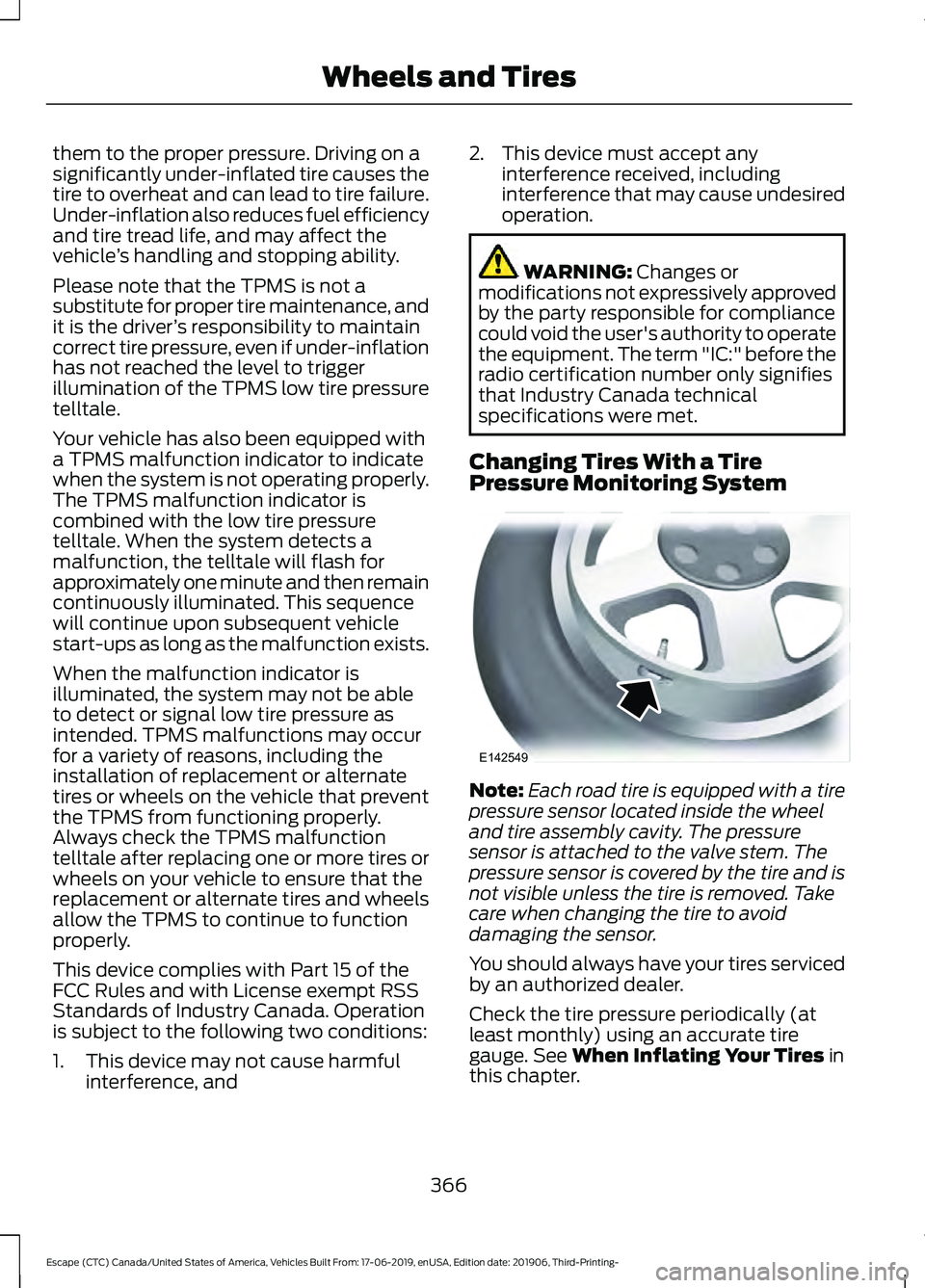
Changing Tires With a Tire
Pressure Monitoring System Note:
Each road tire is equipped with a tire
pressure sensor located inside the wheel
and tire assembly cavity. The pressure
sensor is attached to the valve stem. The
pressure sensor is covered by the tire and is
not visible unless the tire is removed. Take
care when changing the tire to avoid
damaging the sensor.
You should always have your tires serviced
by an authorized dealer.
Check the tire pressure periodically (at
least monthly) using an accurate tire
gauge. See
When Inflating Your Tires in
this chapter.
366
Escape (CTC) Canada/United States of America, Vehicles Built From: 17-06-2019, enUSA, Edition date: 201906, Third-Printing- Wheels and TiresE142549
Page 372 of 553
How Temperature Affects Your Tire
Pressure
The tire pressure monitoring system
monitors tire pressure in each pneumatic
tire. While driving in a normal manner, a
typical passenger tire inflation pressure
may increase about 2
–4 psi (14– 28 kPa)
from a cold start situation. If the vehicle is
stationary overnight with the outside
temperature significantly lower than the
daytime temperature, the tire pressure may
decrease about 3 psi (21 kPa) for a drop of
30°F (17°C) in ambient temperature. This
lower pressure value may be detected by
the tire pressure monitoring system as
being significantly lower than the
recommended inflation pressure and
activate the system warning light for low
tire pressure. If the low tire pressure
warning light is on, visually check each tire
to verify that no tire is flat. If one or more
tires are flat, repair as necessary. Check
the air pressure in the road tires. If any tire
is under-inflated, carefully drive the vehicle
to the nearest location where air can be
added to the tires. Inflate all the tires to
the recommended inflation pressure.
CHANGING A ROAD WHEEL
(IF
EQUIPPED) WARNING:
The tire pressure
monitoring system is not a substitute for
manually checking tire pressures. You
should periodically check tire pressures
using a pressure gauge. Failure to
correctly maintain tire pressures could
increase the risk of tire failure, loss of
control, vehicle rollover and personal
injury. WARNING:
If the tire pressure
monitor sensor becomes damaged it
may not function. Note:
Only use tire sealants in roadside
emergencies as they may cause damage to
the tire pressure monitoring system sensor.
Note: The tire pressure monitoring system
indicator light illuminates when the spare
tire is in use. To restore the full function of
the monitoring system, all road wheels
equipped with tire pressure monitoring
sensors must be mounted on the vehicle.
If you get a flat tire when driving, do not
apply the brake heavily. Instead, gradually
decrease your speed. Hold the steering
wheel firmly and slowly move to a safe
place on the side of the road.
Have a flat serviced by an authorized
dealer in order to prevent damage to the
tire pressure monitoring system sensors.
See
Tire Pressure Monitoring System
(page 365). Replace the spare tire with a
road tire as soon as possible. During
repairing or replacing of the flat tire, have
the authorized dealer inspect the tire
pressure monitoring system sensor for
damage.
Dissimilar Spare Wheel and Tire
Assembly Information WARNING:
Failure to follow these
guidelines could result in an increased
risk of loss of vehicle control, injury or
death.
If you have a dissimilar spare wheel and
tire, then it is intended for temporary use
only. This means that if you need to use it,
you should replace it as soon as possible
with a road wheel and tire assembly that
is the same size and type as the road tires
and wheels that we provided with the
vehicle. If the dissimilar spare tire or wheel
is damaged, replace it instead of repairing
it.
369
Escape (CTC) Canada/United States of America, Vehicles Built From: 17-06-2019, enUSA, Edition date: 201906, Third-Printing- Wheels and Tires
Page 490 of 553
When the oil change message appears in
the information display, it is time for an oil
change. Make sure you perform the oil
change within two weeks or 500 mi
(800 km) of the message appearing. Make
sure you reset the Intelligent Oil-Life
Monitor after each oil change. See
Oil
Change Indicator Reset (page 318).
If your information display resets
prematurely or becomes inoperative, you
should perform the oil change interval at
six months or
5,000 mi (8,000 km) from
your last oil change. Never exceed one year
or
10,000 mi (16,000 km) between oil
change intervals,
Your vehicle is very sophisticated and built
with multiple, complex, performance
systems. Every manufacturer develops
these systems using different
specifications and performance features.
That is why it is important to rely upon your
dealership to properly diagnose and repair
your vehicle.
We have recommended maintenance
intervals for various parts and component
systems based upon engineering testing.
We rely upon this testing to determine the
most appropriate mileage for replacement
of oils and fluids to protect your vehicle at
the lowest overall cost to you and
recommends against maintenance
schedules that deviate from the scheduled
maintenance information.
We strongly recommend the use of only
genuine Ford, Motorcraft or
Ford-authorized re-manufactured
replacement parts engineered for your
vehicle. Additives and Chemicals
This owner's manual and the our
Workshop Manual list the recommended
additives and chemicals for your vehicle.
We do not recommend using chemicals or
additives not approved by us as part of
your vehicle
’s normal maintenance. Please
consult your warranty information.
Oils, Fluids and Flushing
In many cases, fluid discoloration is a
normal operating characteristic and, by
itself, does not necessarily indicate a
concern or that the fluid needs to be
changed. However, a qualified expert, such
as the factory-trained technicians at your
dealership, should inspect discolored fluids
that also show signs of overheating or
foreign material contamination
immediately.
Make sure to change your vehicle ’s oils and
fluids at the specified intervals or in
conjunction with a repair. Flushing is a
viable way to change fluid for many vehicle
sub-systems during scheduled
maintenance. It is critical that systems are
flushed only with new fluid that is the same
as that required to fill and operate the
system or using a Ford-approved flushing
chemical.
Owner Checks and Services
Make sure you perform the following basic
maintenance checks and inspections every
month or at six-month intervals. Check Every Month
Engine oil level.
Function of all interior and exterior lights.
Tires (including spare) for wear and proper pressure.
487
Escape (CTC) Canada/United States of America, Vehicles Built From: 17-06-2019, enUSA, Edition date: 201906, Third-Printing- Scheduled Maintenance
Page 540 of 553
Auto-Start-Stop............................................175
Disabling Auto-Start-Stop.............................. 176
Enabling Auto-Start-Stop............................... 175
Autowipers.......................................................83 Autowipers Settings........................................... 84
Auxiliary Power Points................................163 110 Volt AC Power Point................................... 163
12 Volt DC Power Point..................................... 163
Locations............................................................... 163
AWD See: All-Wheel Drive.......................................... 212
B
Battery See: Changing the 12V Battery..................... 326
Blind Spot Information System..............255
Switching the System On and Off...............257
System Errors....................................................... 257
Using the Blind Spot Information System.............................................................. 256
BLIS See: Blind Spot Information System..........255
Body Styling Kits
..........................................342
Bonnet Lock See: Opening and Closing the Hood...........312
Booster Seats
..................................................29
Types of Booster Seats...................................... 30
Brake Fluid Check........................................325 Brake Fluid Service Interval............................ 326
Brakes................................................................217 General Information........................................... 217
Breaking-In....................................................284
Bulb Specification Chart..........................402
C
Cabin Air Filter...............................................146
Canceling the Set Speed..........................238
Capacities and Specifications - 1.5L EcoBoost™.................................................383
Air Conditioning System................................. 383
Alternative Engine Oil for Extremely Cold Climates........................................................... 386
Automatic Transmission................................. 383
Engine Coolant................................................... 384
Engine Oil............................................................. 385
Fuel Tank.............................................................. 386Grease....................................................................386
Hydraulic Brake System..................................
387
Locks....................................................................... 387
Power Transfer Unit.......................................... 388
Rear Axle.............................................................. 388
Washer Reservoir...............................................389
Capacities and Specifications - 2.0L EcoBoost™
.................................................389
Air Conditioning System................................. 389
Alternative Engine Oil for Extremely Cold Climates........................................................... 392
Automatic Transmission................................ 390
Engine Coolant.................................................... 391
Engine Oil............................................................... 391
Fuel Tank............................................................... 393
Grease.................................................................... 393
Hydraulic Brake System.................................. 393
Locks...................................................................... 394
Power Transfer Unit.......................................... 394
Rear Axle............................................................... 395
Washer Reservoir............................................... 395
Capacities and Specifications - 2.5L, Hybrid Electric Vehicle (HEV)/Plug-In
Hybrid Electric Vehicle (PHEV)...........396
Air Conditioning System................................. 396
Automatic Transmission................................. 397
Engine Coolant................................................... 398
Engine Oil............................................................. 398
Fuel Tank.............................................................. 399
Grease.................................................................... 399
Hydraulic Brake System.................................. 399
Locks..................................................................... 400
Power Transfer Unit......................................... 400
Rear Axle............................................................... 401
Washer Reservoir............................................... 401
Capacities and Specifications
................376
Car Wash See: Cleaning the Exterior.............................. 336
Catalytic Converter......................................193 On-Board Diagnostics (OBD-II)................... 194
Readiness for Inspection and Maintenance (I/M) Testing................................................... 194
Changing a Bulb
............................................331
LED Bulbs (If Equipped)................................. 332
Replacing Direction Indicator Bulbs...........333
Replacing Fog Lamp Bulbs............................ 332
Replacing Headlamp Bulbs............................ 331
537
Escape (CTC) Canada/United States of America, Vehicles Built From: 17-06-2019, enUSA, Edition date: 201906, Third-Printing- Index