light FORD ESCORT 2003 6.G Owners Manual
[x] Cancel search | Manufacturer: FORD, Model Year: 2003, Model line: ESCORT, Model: FORD ESCORT 2003 6.GPages: 184, PDF Size: 1.28 MB
Page 1 of 184
Introduction 4
Instrument Cluster 10
Warning and control lights 10
Gauges 12
Entertainment Systems 14
AM/FM stereo cassette 14
AM/FM stereo with CD 19
Climate Controls 28
Heater only 28
Manual heating and air conditioning 29
Lights 33
Headlamps 33
Turn signal control 36
Bulb replacement 37
Driver Controls 43
Windshield wiper/washer control 43
Steering wheel adjustment 44
Power windows 44
Mirrors 45
Speed control 45
Locks and Security 51
Keys 51
Locks 51
Anti-theft system53
Table of Contents
1
Page 5 of 184
Fuel pump shut-off switchIn the event of an accident the
safety switch will automatically cut off the fuel supply to the
engine. The switch can also be activated through sudden vibration (e.g.
collision when parking). To reset the switch, refer to theFuel pump
shut-off switchin theRoadside emergencieschapter.
SAFETY AND ENVIRONMENT PROTECTION
Warning symbols in this guide
How can you reduce the risk of personal injury and prevent possible
damage to others, your vehicle and its equipment? In this guide, answers
to such questions are contained in comments highlighted by the warning
triangle symbol. These comments should be read and observed.
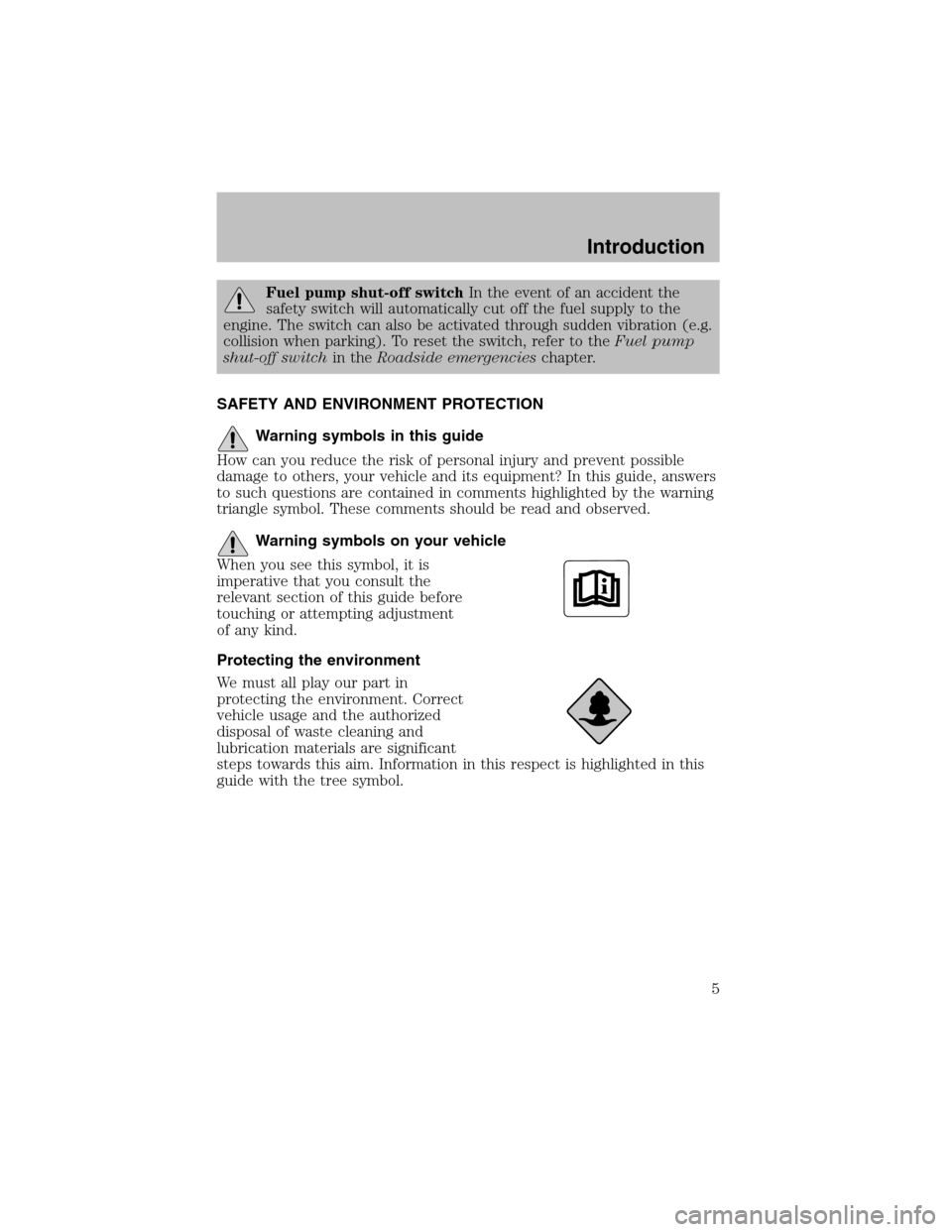
Warning symbols on your vehicle
When you see this symbol, it is
imperative that you consult the
relevant section of this guide before
touching or attempting adjustment
of any kind.
Protecting the environment
We must all play our part in
protecting the environment. Correct
vehicle usage and the authorized
disposal of waste cleaning and
lubrication materials are significant
steps towards this aim. Information in this respect is highlighted in this
guide with the tree symbol.
Introduction
5
Page 8 of 184
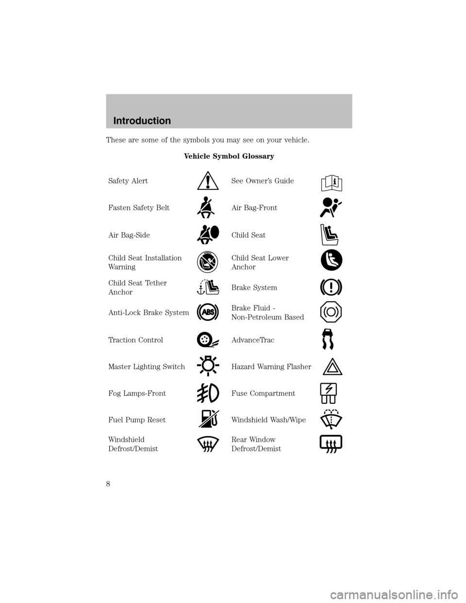
These are some of the symbols you may see on your vehicle.
Vehicle Symbol Glossary
Safety Alert
See Owner’s Guide
Fasten Safety BeltAir Bag-Front
Air Bag-SideChild Seat
Child Seat Installation
WarningChild Seat Lower
Anchor
Child Seat Tether
AnchorBrake System
Anti-Lock Brake SystemBrake Fluid -
Non-PetroleumBased
Traction ControlAdvanceTrac
Master Lighting SwitchHazard Warning Flasher
Fog Lamps-FrontFuse Compartment
Fuel Pump ResetWindshield Wash/Wipe
Windshield
Defrost/DemistRear Window
Defrost/Demist
Introduction
8
Page 10 of 184
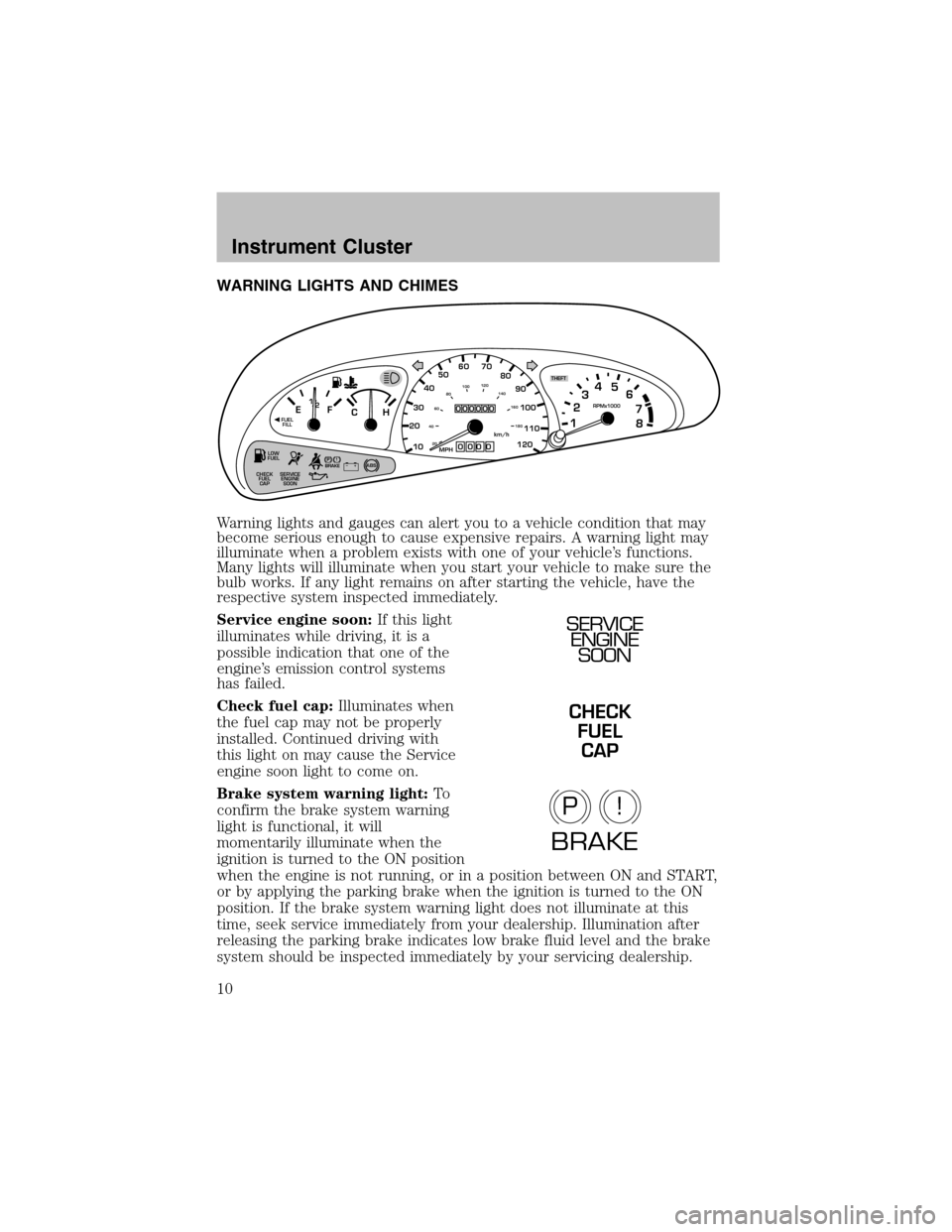
WARNING LIGHTS AND CHIMES
Warning lights and gauges can alert you to a vehicle condition that may
become serious enough to cause expensive repairs. A warning light may
illuminate when a problem exists with one of your vehicle’s functions.
Many lights will illuminate when you start your vehicle to make sure the
bulb works. If any light remains on after starting the vehicle, have the
respective system inspected immediately.
Service engine soon:If this light
illuminates while driving, it is a
possible indication that one of the
engine’s emission control systems
has failed.
Check fuel cap:Illuminates when
the fuel cap may not be properly
installed. Continued driving with
this light on may cause the Service
engine soon light to come on.
Brake system warning light:To
confirmthe brake systemwarning
light is functional, it will
momentarily illuminate when the
ignition is turned to the ON position
when the engine is not running, or in a position between ON and START,
or by applying the parking brake when the ignition is turned to the ON
position. If the brake systemwarning light does not illuminate at this
time, seek service immediately from your dealership. Illumination after
releasing the parking brake indicates low brake fluid level and the brake
system should be inspected immediately by your servicing dealership.
!
THEFT
LOW
FUEL
SERVICE
ENGINE
SOON CHECK
FUEL
CAP
PBRAKEABS+ –MPH
205060 70FUEL
FILLEF
CH1
2 /RPMx1000
1234
5
6
7
8
304080
90
100
110
120
10
20 406080100120
140
160
180km/h
0
000000
00 0
SERVICE
ENGINE
SOON
CHECK
FUEL
CAP
P!
BRAKE
Instrument Cluster
10
Page 11 of 184
Driving a vehicle with the brake systemwarning light on is
dangerous. A significant decrease in braking performance may
occur. It will take you longer to stop the vehicle. Have the vehicle
checked by your dealer immediately.
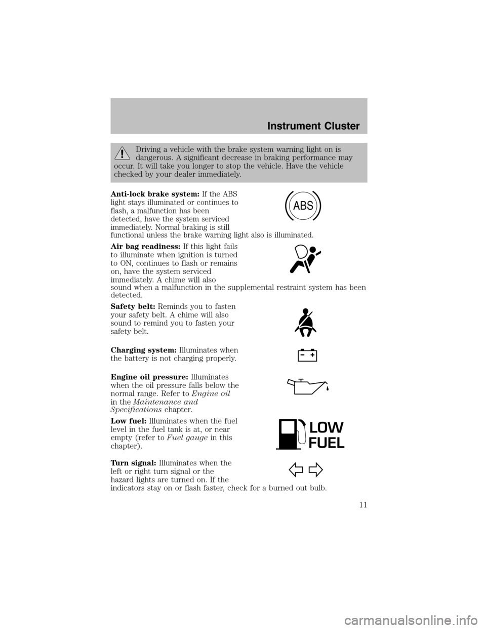
Anti-lock brake system:If the ABS
light stays illuminated or continues to
flash, a malfunction has been
detected, have the systemserviced
immediately. Normal braking is still
functional unless the brake warning light also is illuminated.
Air bag readiness:If this light fails
to illuminate when ignition is turned
to ON, continues to flash or remains
on, have the systemserviced
immediately. A chime will also
sound when a malfunction in the supplemental restraint system has been
detected.
Safety belt:Reminds you to fasten
your safety belt. A chime will also
sound to remind you to fasten your
safety belt.
Charging system:Illuminates when
the battery is not charging properly.
Engine oil pressure:Illuminates
when the oil pressure falls below the
normal range. Refer toEngine oil
in theMaintenance and
Specificationschapter.
Low fuel:Illuminates when the fuel
level in the fuel tank is at, or near
empty (refer toFuel gaugein this
chapter).
Turn signal:Illuminates when the
left or right turn signal or the
hazard lights are turned on. If the
indicators stay on or flash faster, check for a burned out bulb.
ABS
LOW
FUEL
Instrument Cluster
11
Page 18 of 184
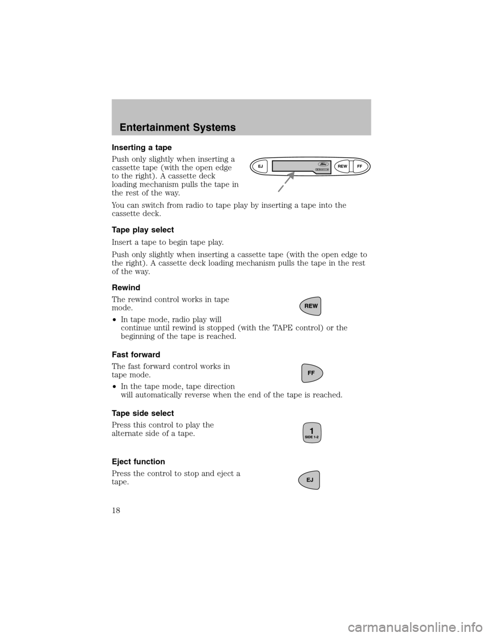
Inserting a tape
Push only slightly when inserting a
cassette tape (with the open edge
to the right). A cassette deck
loading mechanism pulls the tape in
the rest of the way.
You can switch fromradio to tape play by inserting a tape into the
cassette deck.
Tape play select
Insert a tape to begin tape play.
Push only slightly when inserting a cassette tape (with the open edge to
the right). A cassette deck loading mechanism pulls the tape in the rest
of the way.
Rewind
The rewind control works in tape
mode.
•In tape mode, radio play will
continue until rewind is stopped (with the TAPE control) or the
beginning of the tape is reached.
Fast forward
The fast forward control works in
tape mode.
•In the tape mode, tape direction
will automatically reverse when the end of the tape is reached.
Tape side select
Press this control to play the
alternate side of a tape.
Eject function
Press the control to stop and eject a
tape.
EJREW
FFDOLBY B NR
EJ
Entertainment Systems
18
Page 26 of 184
RADIO FREQUENCIES
AM and FM frequencies are established by the Federal Communications
Commission (FCC) and the Canadian Radio and Telecommunications
Commission (CRTC). Those frequencies are:
AM - 530, 540–1700, 1710 kHz
FM- 87.7, 87.9–107.7, 107.9 MHz
RADIO RECEPTION FACTORS
There are three factors that can effect radio reception:
•Distance/strength: The further you travel froman FM station, the
weaker the signal and the weaker the reception.
•Terrain: Hills, mountains, tall buildings, power lines, electric fences,
traffic lights and thunderstorms can interfere with your reception.
•Station overload: When you pass a broadcast tower, a stronger signal
may overtake a weaker one and play while the weak station frequency
is displayed.
CASSETTE/PLAYER CARE
Do:
•Use only cassettes that are 90 minutes long or less.
•Tighten very loose tapes by inserting a finger or pencil into the hole
and turning the hub.
•Remove loose labels before inserting tapes.
•Allow tapes which have been subjected to extreme heat, humidity or
cold to reach a moderate temperature before playing.
•Clean the cassette player head with a cassette cleaning cartridge after
10–12 hours of play to maintain good sound/operation.
Don’t:
•Expose tapes to direct sunlight, extreme humidity, heat or cold.
•Leave tapes in the cassette player for a long time when not being
played.
Entertainment Systems
26
Page 27 of 184

CD/CD PLAYER CARE
Do:
•Handle discs by their edges only. Never touch the playing surface.
•Inspect discs before playing. Clean only with an approved CD cleaner
and wipe fromthe center out.
Don’t:
•Expose discs to direct sunlight or heat sources for extended periods
of time.
•Insert more than one disc into each slot of the CD changer magazine.
•Clean using a circular motion.
CD units are designed to play commercially pressed 12 cm (4.75
in) audio compact discs only. Due to technical incompatibility,
certain recordable and re-recordable compact discs may not
function correctly when used in Ford CD players. Irregular
shaped CDs, CDs with a scratch protection film attached, and CDs
with homemade paper (adhesive) labels should not be inserted
into the CD player. The label may peel and cause the CD to
become jammed. It is recommended that homemade CDs be
identified with permanent felt tip marker rather than adhesive
labels. Ball point pens may damage CDs. Please contact your
dealer for further information.
AUDIO SYSTEM WARRANTY AND SERVICE
Refer to theWarranty Guidefor audio systemwarranty information. If
service is necessary, see your dealer or qualified technician.
Entertainment Systems
27
Page 30 of 184
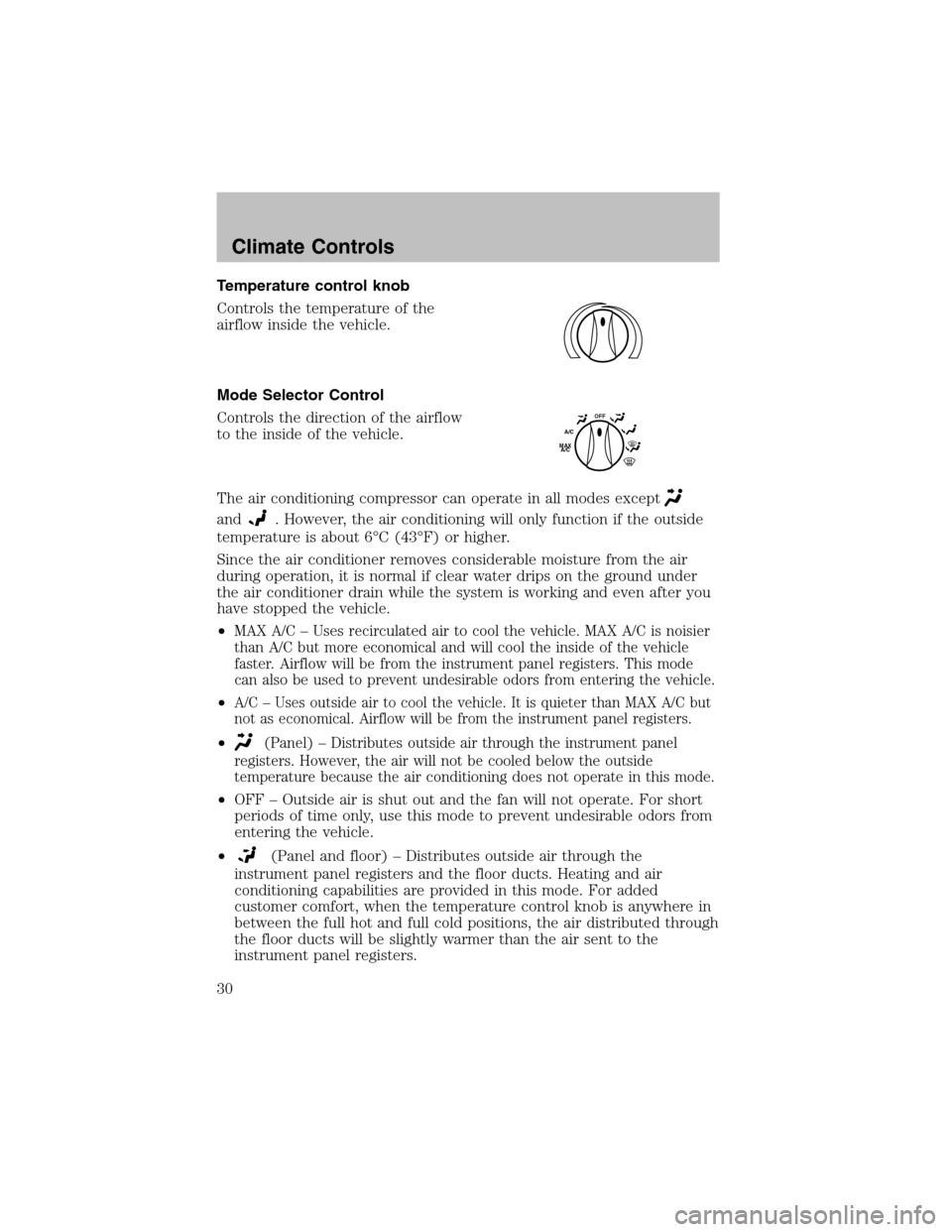
Temperature control knob
Controls the temperature of the
airflow inside the vehicle.
Mode Selector Control
Controls the direction of the airflow
to the inside of the vehicle.
The air conditioning compressor can operate in all modes except
and. However, the air conditioning will only function if the outside
temperature is about 6°C (43°F) or higher.
Since the air conditioner removes considerable moisture from the air
during operation, it is normal if clear water drips on the ground under
the air conditioner drain while the systemis working and even after you
have stopped the vehicle.
•
MAX A/C – Uses recirculated air to cool the vehicle. MAX A/C is noisier
than A/C but more economical and will cool the inside of the vehicle
faster. Airflow will be from the instrument panel registers. This mode
can also be used to prevent undesirable odors fromentering the vehicle.
•A/C – Uses outside air to cool the vehicle. It is quieter than MAX A/C but
not as economical. Airflow will be from the instrument panel registers.
•(Panel) – Distributes outside air through the instrument panel
registers. However, the air will not be cooled below the outside
temperature because the air conditioning does not operate in this mode.
•OFF – Outside air is shut out and the fan will not operate. For short
periods of time only, use this mode to prevent undesirable odors from
entering the vehicle.
•
(Panel and floor) – Distributes outside air through the
instrument panel registers and the floor ducts. Heating and air
conditioning capabilities are provided in this mode. For added
customer comfort, when the temperature control knob is anywhere in
between the full hot and full cold positions, the air distributed through
the floor ducts will be slightly warmer than the air sent to the
instrument panel registers.
OFF
A/C
MAX
A/C
Climate Controls
30
Page 31 of 184

•(Floor) – Distributes outside air through the floor ducts.
However, the air will not be cooled below the outside temperature
because the air conditioning does not operate in this mode.
•
(Floor and defrost) – Distributes outside air through the
windshield defroster ducts and the floor ducts. Heating and air
conditioning capabilities are provided in this mode. For added
customer comfort, the air distributed through the floor ducts will be
slightly warmer than the air sent to the windshield defroster ducts. If
the temperature is about 6°C (43°F) or higher, the air conditioner will
automatically dehumidify the air to reduce fogging.
•
(Defrost) – Distributes outside air through the windshield
defroster ducts. It can be used to clear ice or fog fromthe windshield.
If the temperature is about 6°C (43°F) or higher, the air conditioner
will automatically dehumidify the air to reduce fogging.
Operating tips
•In humid weather conditions, place the climate control system in
Defrost mode before driving. This will reduce fogging on your
windshield. Once the windshield has been cleared, operate the climate
control systemas desired.
•To reduce humidity buildup inside the vehicle in cold weather
conditions, don’t drive with the climate control system in the OFF or
MAX A/C position.
•To reduce humidity buildup inside the vehicle in warm weather
conditions, don’t drive with the climate control system in the OFF
position.
•Under normal weather conditions, your vehicle’s climate control
systemshould be left in any position other than the MAX A/C or OFF
when the vehicle is parked. This allows the vehicle to “breathe”
through the outside air inlet duct.
•Under snowy or dirty weather conditions, your vehicle’s climate
control systemshould be left in the OFF position when the vehicle is
parked. This allows the climate control system to be free from
contamination of outside pollutants.
•If your vehicle has been parked with the windows closed during warm
weather conditions, the air conditioner will performmore efficiently in
cooling the vehicle if driven for two or three minutes with the
windows open. This will force most of the hot, stale air out of the
vehicle. Once the vehicle has been “aired out”, operate the climate
control systemas desired.
Climate Controls
31