ABS FORD ESCORT 2003 7.G Owners Manual
[x] Cancel search | Manufacturer: FORD, Model Year: 2003, Model line: ESCORT, Model: FORD ESCORT 2003 7.GPages: 184, PDF Size: 1.28 MB
Page 10 of 184
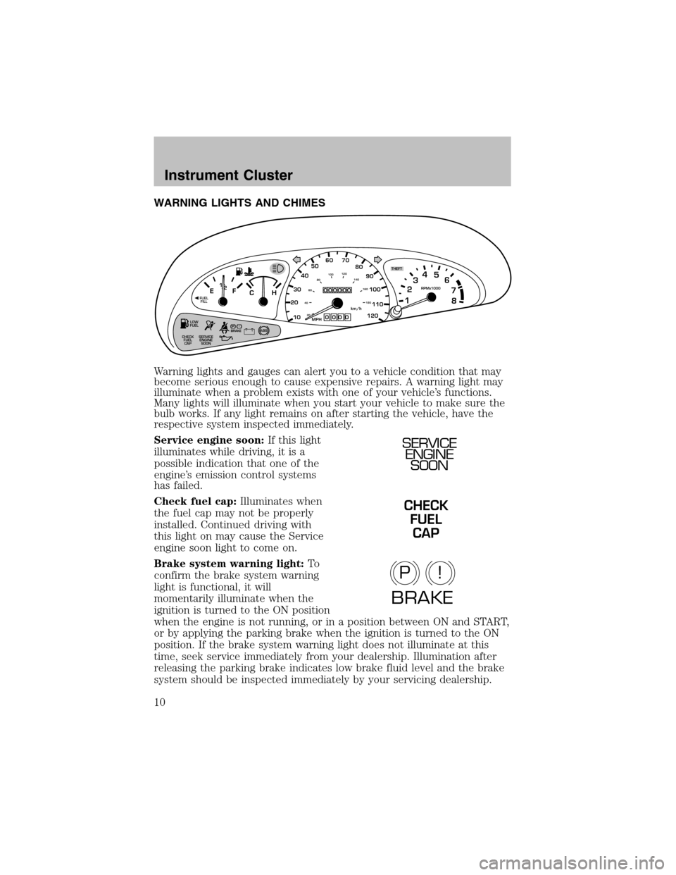
WARNING LIGHTS AND CHIMES
Warning lights and gauges can alert you to a vehicle condition that may
become serious enough to cause expensive repairs. A warning light may
illuminate when a problem exists with one of your vehicle’s functions.
Many lights will illuminate when you start your vehicle to make sure the
bulb works. If any light remains on after starting the vehicle, have the
respective system inspected immediately.
Service engine soon:If this light
illuminates while driving, it is a
possible indication that one of the
engine’s emission control systems
has failed.
Check fuel cap:Illuminates when
the fuel cap may not be properly
installed. Continued driving with
this light on may cause the Service
engine soon light to come on.
Brake system warning light:To
confirmthe brake systemwarning
light is functional, it will
momentarily illuminate when the
ignition is turned to the ON position
when the engine is not running, or in a position between ON and START,
or by applying the parking brake when the ignition is turned to the ON
position. If the brake systemwarning light does not illuminate at this
time, seek service immediately from your dealership. Illumination after
releasing the parking brake indicates low brake fluid level and the brake
system should be inspected immediately by your servicing dealership.
!
THEFT
LOW
FUEL
SERVICE
ENGINE
SOON CHECK
FUEL
CAP
PBRAKEABS+ –MPH
205060 70FUEL
FILLEF
CH1
2 /RPMx1000
1234
5
6
7
8
304080
90
100
110
120
10
20 406080100120
140
160
180km/h
0
000000
00 0
SERVICE
ENGINE
SOON
CHECK
FUEL
CAP
P!
BRAKE
Instrument Cluster
10
Page 11 of 184
Driving a vehicle with the brake systemwarning light on is
dangerous. A significant decrease in braking performance may
occur. It will take you longer to stop the vehicle. Have the vehicle
checked by your dealer immediately.
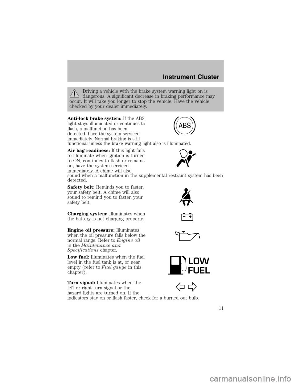
Anti-lock brake system:If the ABS
light stays illuminated or continues to
flash, a malfunction has been
detected, have the systemserviced
immediately. Normal braking is still
functional unless the brake warning light also is illuminated.
Air bag readiness:If this light fails
to illuminate when ignition is turned
to ON, continues to flash or remains
on, have the systemserviced
immediately. A chime will also
sound when a malfunction in the supplemental restraint system has been
detected.
Safety belt:Reminds you to fasten
your safety belt. A chime will also
sound to remind you to fasten your
safety belt.
Charging system:Illuminates when
the battery is not charging properly.
Engine oil pressure:Illuminates
when the oil pressure falls below the
normal range. Refer toEngine oil
in theMaintenance and
Specificationschapter.
Low fuel:Illuminates when the fuel
level in the fuel tank is at, or near
empty (refer toFuel gaugein this
chapter).
Turn signal:Illuminates when the
left or right turn signal or the
hazard lights are turned on. If the
indicators stay on or flash faster, check for a burned out bulb.
ABS
LOW
FUEL
Instrument Cluster
11
Page 12 of 184
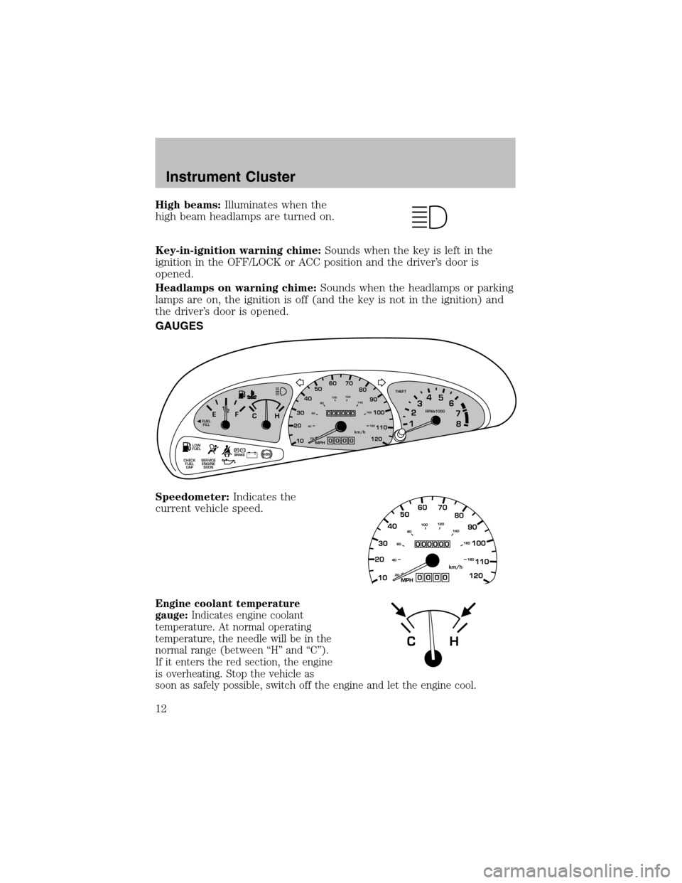
High beams:Illuminates when the
high beamheadlamps are turned on.
Key-in-ignition warning chime:Sounds when the key is left in the
ignition in the OFF/LOCK or ACC position and the driver’s door is
opened.
Headlamps on warning chime:Sounds when the headlamps or parking
lamps are on, the ignition is off (and the key is not in the ignition) and
the driver’s door is opened.
GAUGES
Speedometer:Indicates the
current vehicle speed.
Engine coolant temperature
gauge:Indicates engine coolant
temperature. At normal operating
temperature, the needle will be in the
normal range (between “H” and “C”).
If it enters the red section, the engine
is overheating. Stop the vehicle as
soon as safely possible, switch off the engine and let the engine cool.
THEFT
LOW
FUEL
SERVICE
ENGINE
SOON CHECK
FUEL
CAP
ABS+ –MPH
205060 70FUEL
FILLEF
CH1
2 /RPMx1000
1234
5
6
7
8
304080
90
100
110
120
10
20 406080100120
140
160
180km/h
0
000000
000! PBRAKE
Instrument Cluster
12
Page 38 of 184
Function Trade Number
Front park/turn lamps 3157K
Foglamps (if equipped) 881
Headlamps-aero high and low beam 9007
Rear license plate lamps 168
High-mount brake lamp 921
Backup lamps 3156K
Brake lamps 3157K
Interior overhead lamp 12V/10W
All replacement bulbs are clear in color except where noted.
To replace all instrument panel lights - see your dealer
INTERIOR BULBS
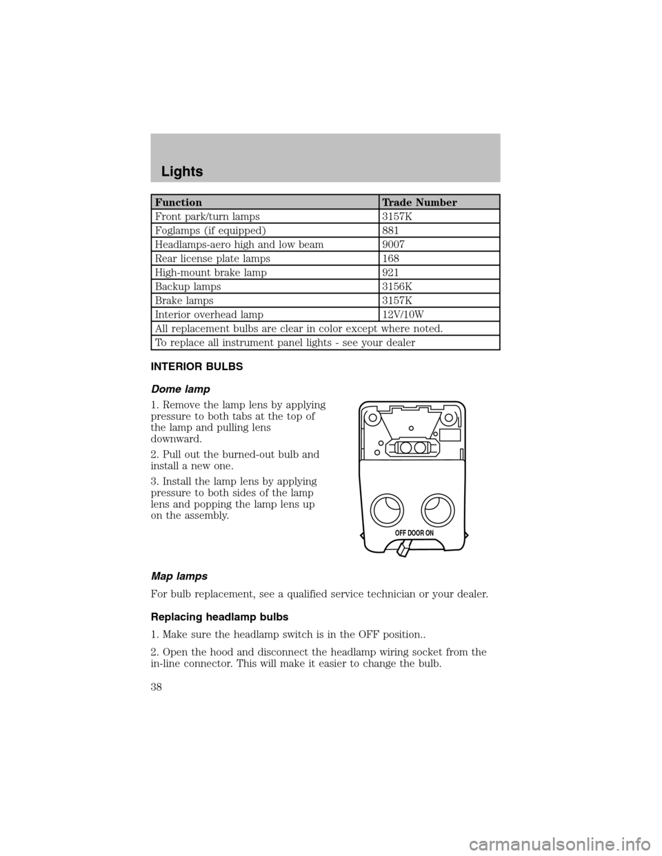
Dome lamp
1. Remove the lamp lens by applying
pressure to both tabs at the top of
the lamp and pulling lens
downward.
2. Pull out the burned-out bulb and
install a new one.
3. Install the lamp lens by applying
pressure to both sides of the lamp
lens and popping the lamp lens up
on the assembly.
Map lamps
For bulb replacement, see a qualified service technician or your dealer.
Replacing headlamp bulbs
1. Make sure the headlamp switch is in the OFF position..
2. Open the hood and disconnect the headlamp wiring socket from the
in-line connector. This will make it easier to change the bulb.
OFF DOOR ON
Lights
38
Page 39 of 184
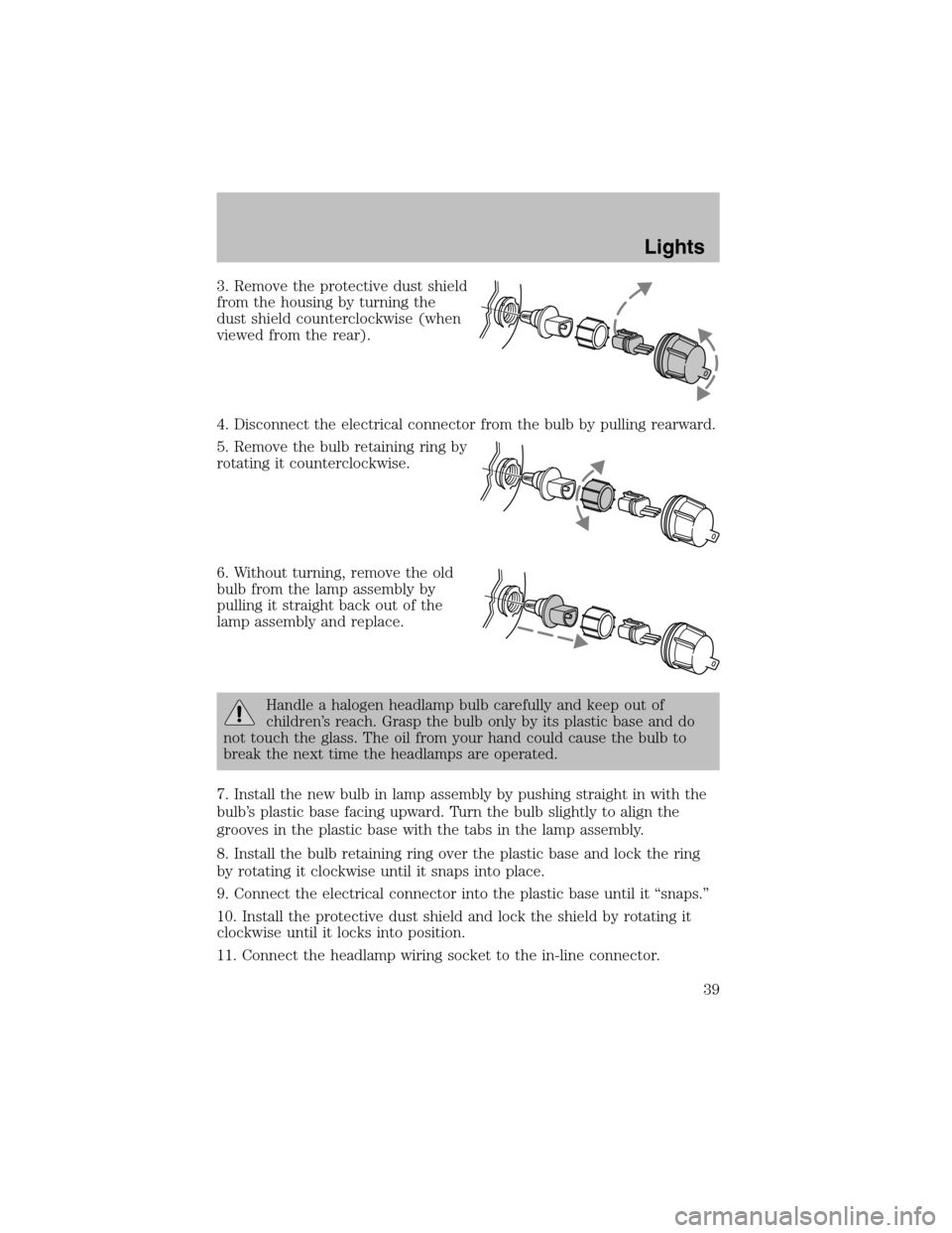
3. Remove the protective dust shield
fromthe housing by turning the
dust shield counterclockwise (when
viewed fromthe rear).
4. Disconnect the electrical connector fromthe bulb by pulling rearward.
5. Remove the bulb retaining ring by
rotating it counterclockwise.
6. Without turning, remove the old
bulb from the lamp assembly by
pulling it straight back out of the
lamp assembly and replace.
Handle a halogen headlamp bulb carefully and keep out of
children’s reach. Grasp the bulb only by its plastic base and do
not touch the glass. The oil fromyour hand could cause the bulb to
break the next time the headlamps are operated.
7. Install the new bulb in lamp assembly by pushing straight in with the
bulb’s plastic base facing upward. Turn the bulb slightly to align the
grooves in the plastic base with the tabs in the lamp assembly.
8. Install the bulb retaining ring over the plastic base and lock the ring
by rotating it clockwise until it snaps into place.
9. Connect the electrical connector into the plastic base until it “snaps.”
10. Install the protective dust shield and lock the shield by rotating it
clockwise until it locks into position.
11. Connect the headlamp wiring socket to the in-line connector.
Lights
39
Page 87 of 184
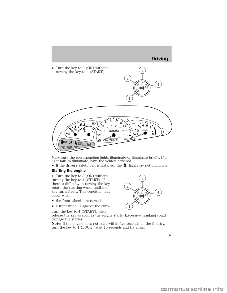
•Turn the key to 3 (ON) without
turning the key to 4 (START).
Make sure the corresponding lights illuminate or illuminate briefly. If a
light fails to illuminate, have the vehicle serviced.
•If the driver’s safety belt is fastened, the
light may not illuminate.
Starting the engine
1. Turn the key to 3 (ON) without
turning the key to 4 (START). If
there is difficulty in turning the key,
rotate the steering wheel until the
key turns freely. This condition may
occur when:
•the front wheels are turned
•a front wheel is against the curb
Turn the key to 4 (START), then
release the key as soon as the engine starts. Excessive cranking could
damage the starter.
Note:If the engine does not start within five seconds on the first try,
turn the key to 1 (LOCK), wait 10 seconds and try again.
LOCKACCONSTART0IIIIII4
3
2
1
!
THEFT
LOW
FUEL
SERVICE
ENGINE
SOON CHECK
FUEL
CAP
PBRAKEABS+ –MPH
205060 70FUEL
FILLEF
CH1
2 /RPMx1000
1234
5
6
7
8
304080
90
100
110
120
10
20 406080100120
140
160
180km/h
0
000000
00 0
LOCKACCONSTART0IIIIII4
3
2
1
Driving
87
Page 89 of 184
If you are driving down a long or steep hill, shift to a lower gear.
Do not apply your brakes continuously, as they may overheat
and become less effective.
Under normal operating conditions, brake dust may accumulate on the
wheels. Some brake dust is inevitable as brakes wear and does not
contribute to brake noise. The use of modern friction materials with
emphasis on improved performance and environmental considerations
can lead to more dust than in the past. Brake dust can be cleaned by
weekly washing with soapy water and a soft sponge. Heavier deposits can
be removed with Motorcraft Wheel and Tire Cleaner (ZC-37–A).
Anti-lock brake system (ABS) (if equipped)
On vehicles equipped with an anti-lock braking system(ABS), a noise
from the hydraulic pump motor and pulsation in the pedal may be
observed during ABS braking events. Pedal pulsation coupled with noise
while braking under panic conditions or on loose gravel, bumps, wet or
snowy roads is normal and indicates proper functioning of the vehicle’s
anti-lock brake system. The ABS performs a self-check after you start
the engine and begin to drive away. A brief mechanical noise may be
heard during this test. This is normal. If a malfunction is found, the ABS
warning light will come on. If the vehicle has continuous vibration or
shudder in the steering wheel while braking, the vehicle should be
inspected by a qualified service technician.
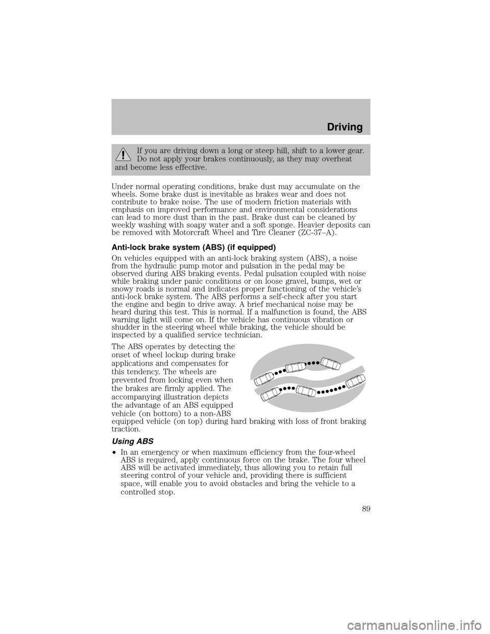
The ABS operates by detecting the
onset of wheel lockup during brake
applications and compensates for
this tendency. The wheels are
prevented fromlocking even when
the brakes are firmly applied. The
accompanying illustration depicts
the advantage of an ABS equipped
vehicle (on bottom) to a non-ABS
equipped vehicle (on top) during hard braking with loss of front braking
traction.
Using ABS
•In an emergency or when maximum efficiency from the four-wheel
ABS is required, apply continuous force on the brake. The four wheel
ABS will be activated immediately, thus allowing you to retain full
steering control of your vehicle and, providing there is sufficient
space, will enable you to avoid obstacles and bring the vehicle to a
controlled stop.
Driving
89
Page 90 of 184
•The anti-lock systemdoes not reduce stopping distance. Always leave
enough roombetween your vehicle and the vehicle in front of you to
stop.
•We recommend that you familiarize yourself with this braking
technique. However, avoid taking any unnecessary risks.
ABS warning lamp
ABS
TheABSwarning lamp in the instrument cluster momentarily illuminates
when the ignition is turned to the ON position. If the light does not
illuminate momentarily at start up, remains on or continues to flash, the
ABS needs to be serviced.
With the ABS light on, the anti-lock
brake systemis disabled and normal
braking is still effective unless the
brake warning light also remains
illuminated with parking brake
released. (If your brake warning lamp illuminates, have your vehicle
serviced immediately.)
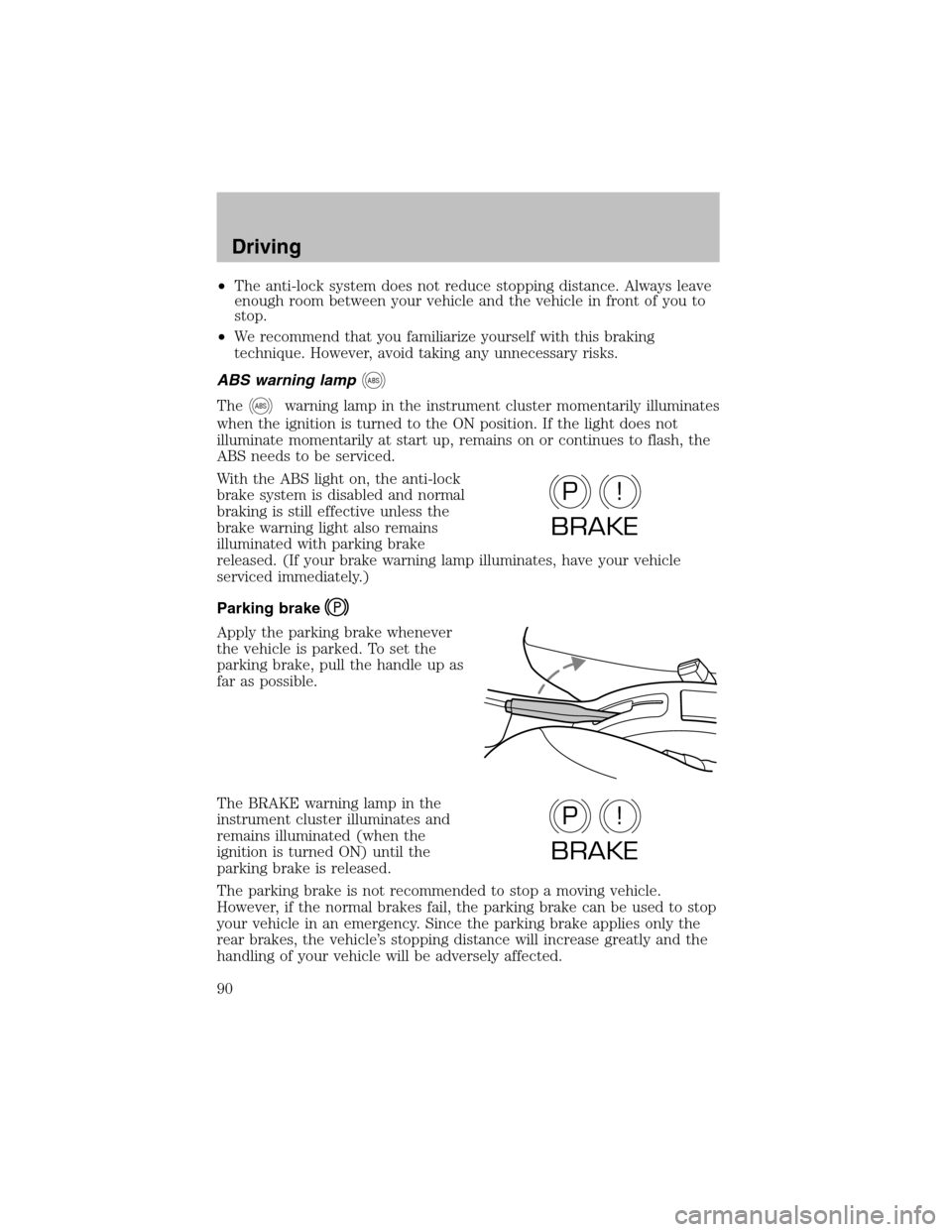
Parking brake
Apply the parking brake whenever
the vehicle is parked. To set the
parking brake, pull the handle up as
far as possible.
The BRAKE warning lamp in the
instrument cluster illuminates and
remains illuminated (when the
ignition is turned ON) until the
parking brake is released.
The parking brake is not recommended to stop a moving vehicle.
However, if the normal brakes fail, the parking brake can be used to stop
your vehicle in an emergency. Since the parking brake applies only the
rear brakes, the vehicle’s stopping distance will increase greatly and the
handling of your vehicle will be adversely affected.
P!
BRAKE
P!
BRAKE
Driving
90
Page 107 of 184

Passenger compartment fuse panel
The fuses are coded as follows:
Fuse/Relay
LocationFuse Amp
RatingPassenger Compartment Fuse
Panel Description
DRL 10A Daytime Running Lamps (DRL)
HAZARD 15A Hazard flasher
ROOM 10A Engine controls, RAP system,
Radio, Shift lock, Courtesy lamps,
Starting system, Warning chime,
Instrument cluster
ENGINE 15A Electronic automatic transaxle,
Ignition system, Constant control
relay module (PCM relay)
RADIO 5A Power mirrors, Radio, RAP system
DOOR LOCK 30A Power door locks
HORN 15A Horn, Shift lock
AIR COND 15A A/C-heater, ABS
METER 10A Backup lamps, Engine coolant
level switch, Instrument cluster,
Rear window defrost, Shift lock,
Warning chime, Turn signal switch
(DRL) (DOOR LK)
STOP
HAZARD HORN
TAIL
ROOM(AIR COND) (SUN ROOF)
ENGINE METER(ASC)
RADIO
WIPER
–P. Window (C.B.)
(FOG) CIGAR
(AUDIO)
AIR BAGFUEL INJ
HEATER
–
Roadside Emergencies
107
Page 109 of 184
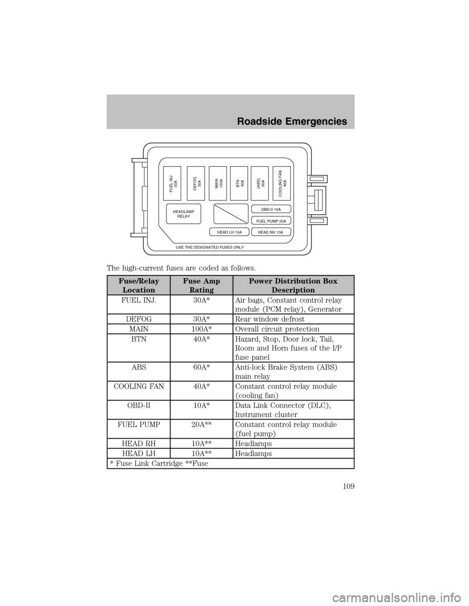
The high-current fuses are coded as follows.
Fuse/Relay
LocationFuse Amp
RatingPower Distribution Box
Description
FUEL INJ. 30A* Air bags, Constant control relay
module (PCM relay), Generator
DEFOG 30A* Rear window defrost
MAIN 100A* Overall circuit protection
BTN 40A* Hazard, Stop, Door lock, Tail,
Roomand Horn fuses of the I/P
fuse panel
ABS 60A* Anti-lock Brake System(ABS)
main relay
COOLING FAN 40A* Constant control relay module
(cooling fan)
OBD-II 10A* Data Link Connector (DLC),
Instrument cluster
FUEL PUMP 20A** Constant control relay module
(fuel pump)
HEAD RH 10A** Headlamps
HEAD LH 10A** Headlamps
* Fuse Link Cartridge **Fuse
USE THE DESIGNATED FUSES ONLY
FUEL INJ
30A
DEFOG
30A
MAIN
100A
COOLING FAN
40A (ABS)
60A BTN
40A
HEADLAMP
RELAY
FUEL PUMP 20AOBD-II 10A
HEAD RH 10A HEAD LH 10A
Roadside Emergencies
109