FORD EXCURSION 2005 1.G Owners Manual
Manufacturer: FORD, Model Year: 2005, Model line: EXCURSION, Model: FORD EXCURSION 2005 1.GPages: 280, PDF Size: 2.76 MB
Page 201 of 280
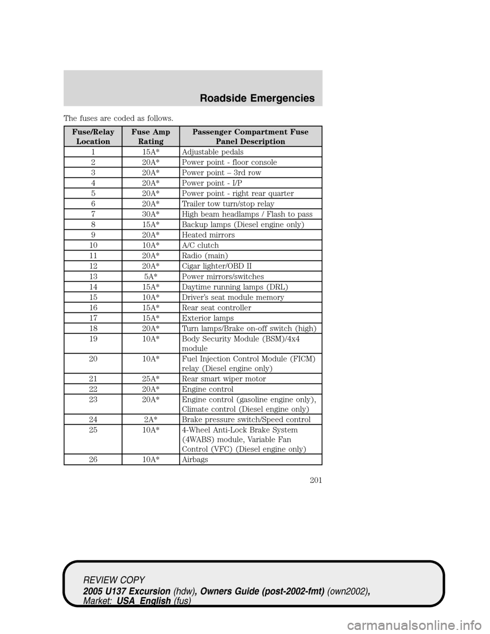
The fuses are coded as follows.
Fuse/Relay
LocationFuse Amp
RatingPassenger Compartment Fuse
Panel Description
1 15A* Adjustable pedals
2 20A* Power point - floor console
3 20A* Power point–3rd row
4 20A* Power point - I/P
5 20A* Power point - right rear quarter
6 20A* Trailer tow turn/stop relay
7 30A* High beam headlamps / Flash to pass
8 15A* Backup lamps (Diesel engine only)
9 20A* Heated mirrors
10 10A* A/C clutch
11 20A* Radio (main)
12 20A* Cigar lighter/OBD II
13 5A* Power mirrors/switches
14 15A* Daytime running lamps (DRL)
15 10A* Driver’s seat module memory
16 15A* Rear seat controller
17 15A* Exterior lamps
18 20A* Turn lamps/Brake on-off switch (high)
19 10A* Body Security Module (BSM)/4x4
module
20 10A* Fuel Injection Control Module (FICM)
relay (Diesel engine only)
21 25A* Rear smart wiper motor
22 20A* Engine control
23 20A* Engine control (gasoline engine only),
Climate control (Diesel engine only)
24 2A* Brake pressure switch/Speed control
25 10A* 4-Wheel Anti-Lock Brake System
(4WABS) module, Variable Fan
Control (VFC) (Diesel engine only)
26 10A* Airbags
REVIEW COPY
2005 U137 Excursion(hdw), Owners Guide (post-2002-fmt)(own2002),
Market:USA_English(fus)
Roadside Emergencies
201
Page 202 of 280
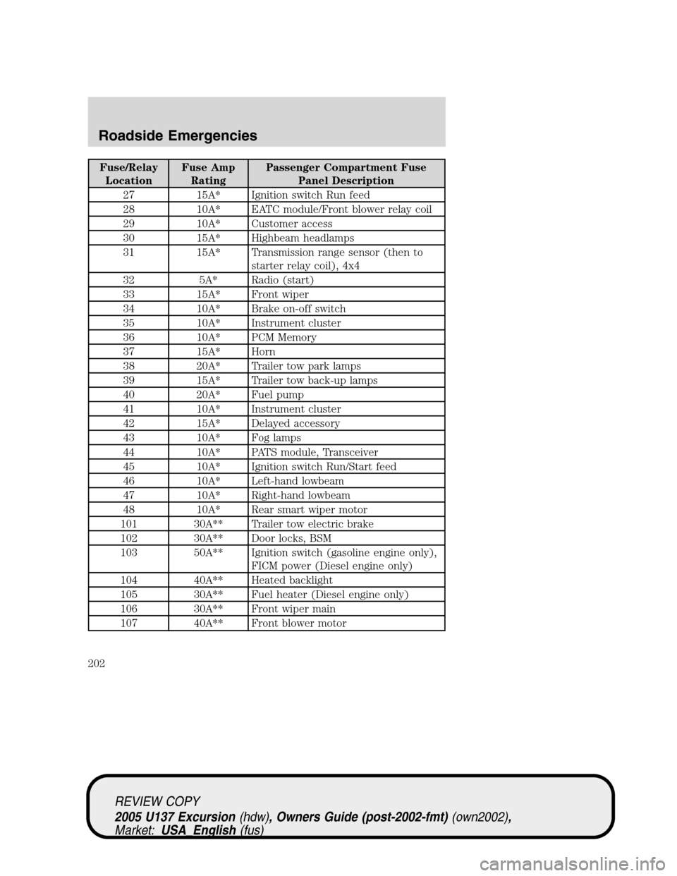
Fuse/Relay
LocationFuse Amp
RatingPassenger Compartment Fuse
Panel Description
27 15A* Ignition switch Run feed
28 10A* EATC module/Front blower relay coil
29 10A* Customer access
30 15A* Highbeam headlamps
31 15A* Transmission range sensor (then to
starter relay coil), 4x4
32 5A* Radio (start)
33 15A* Front wiper
34 10A* Brake on-off switch
35 10A* Instrument cluster
36 10A* PCM Memory
37 15A* Horn
38 20A* Trailer tow park lamps
39 15A* Trailer tow back-up lamps
40 20A* Fuel pump
41 10A* Instrument cluster
42 15A* Delayed accessory
43 10A* Fog lamps
44 10A* PATS module, Transceiver
45 10A* Ignition switch Run/Start feed
46 10A* Left-hand lowbeam
47 10A* Right-hand lowbeam
48 10A* Rear smart wiper motor
101 30A** Trailer tow electric brake
102 30A** Door locks, BSM
103 50A** Ignition switch (gasoline engine only),
FICM power (Diesel engine only)
104 40A** Heated backlight
105 30A** Fuel heater (Diesel engine only)
106 30A** Front wiper main
107 40A** Front blower motor
REVIEW COPY
2005 U137 Excursion(hdw), Owners Guide (post-2002-fmt)(own2002),
Market:USA_English(fus)
Roadside Emergencies
202
Page 203 of 280
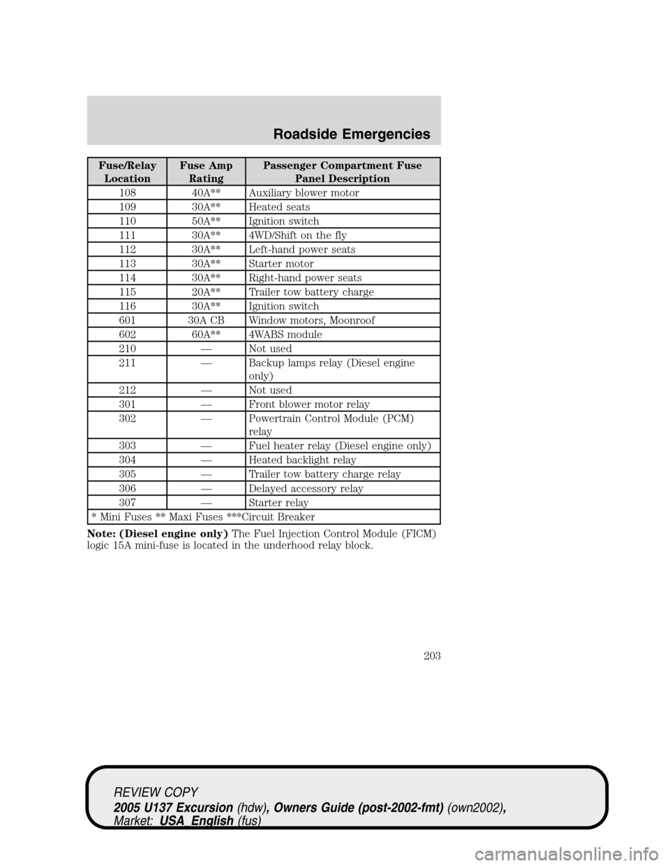
Fuse/Relay
LocationFuse Amp
RatingPassenger Compartment Fuse
Panel Description
108 40A** Auxiliary blower motor
109 30A** Heated seats
110 50A** Ignition switch
111 30A** 4WD/Shift on the fly
112 30A** Left-hand power seats
113 30A** Starter motor
114 30A** Right-hand power seats
115 20A** Trailer tow battery charge
116 30A** Ignition switch
601 30A CB Window motors, Moonroof
602 60A** 4WABS module
210—Not used
211—Backup lamps relay (Diesel engine
only)
212—Not used
301—Front blower motor relay
302—Powertrain Control Module (PCM)
relay
303—Fuel heater relay (Diesel engine only)
304—Heated backlight relay
305—Trailer tow battery charge relay
306—Delayed accessory relay
307—Starter relay
* Mini Fuses ** Maxi Fuses ***Circuit Breaker
Note: (Diesel engine only)The Fuel Injection Control Module (FICM)
logic 15A mini-fuse is located in the underhood relay block.
REVIEW COPY
2005 U137 Excursion(hdw), Owners Guide (post-2002-fmt)(own2002),
Market:USA_English(fus)
Roadside Emergencies
203
Page 204 of 280
JUMP STARTING YOUR VEHICLE
The gases around the battery can explode if exposed to flames,
sparks, or lit cigarettes. An explosion could result in injury or
vehicle damage.
Batteries contain sulfuric acid which can burn skin, eyes and
clothing, if contacted.
Do not attempt to push-start your vehicle. Automatic
transmissions do not have push-start capability; doing so may
damage the catalytic converter.
Preparing your vehicle
When the battery is disconnected or a new battery is installed, the
transmission must relearn its shift strategy. As a result, the transmission
may have firm and/or soft shifts. This operation is considered normal and
will not affect function or durability of the transmission. Over time, the
adaptive learning process will fully update transmission operation.
1.Use only a 12–volt supply to start your vehicle.
2. Do not disconnect the battery of the disabled vehicle as this could
damage the vehicle’s electrical system.
3. Park the booster vehicle close to the hood of the disabled vehicle
making sure the two vehiclesdo nottouch. Set the parking brake on
both vehicles and stay clear of the engine cooling fan and other moving
parts.
4. Check all battery terminals and remove any excessive corrosion before
you attach the battery cables. Ensure that vent caps are tight and level.
5. Turn the heater fan on in both vehicles to protect any electrical
surges. Turn all other accessories off.
REVIEW COPY
2005 U137 Excursion(hdw), Owners Guide (post-2002-fmt)(own2002),
Market:USA_English(fus)
Roadside Emergencies
204
Page 205 of 280
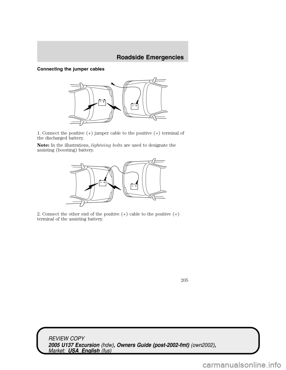
Connecting the jumper cables
1. Connect the positive (+) jumper cable to the positive (+) terminal of
the discharged battery.
Note:In the illustrations,lightning boltsare used to designate the
assisting (boosting) battery.
2. Connect the other end of the positive (+) cable to the positive (+)
terminal of the assisting battery.
+–+–
+–+–
REVIEW COPY
2005 U137 Excursion(hdw), Owners Guide (post-2002-fmt)(own2002),
Market:USA_English(fus)
Roadside Emergencies
205
Page 206 of 280
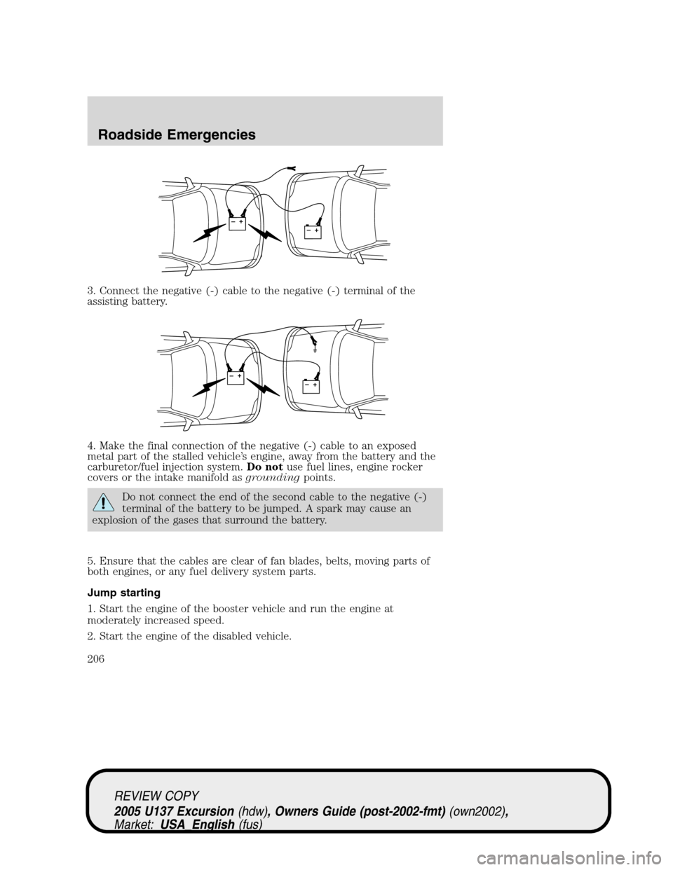
3. Connect the negative (-) cable to the negative (-) terminal of the
assisting battery.
4. Make the final connection of the negative (-) cable to an exposed
metal part of the stalled vehicle’s engine, away from the battery and the
carburetor/fuel injection system.Do notuse fuel lines, engine rocker
covers or the intake manifold asgroundingpoints.
Do not connect the end of the second cable to the negative (-)
terminal of the battery to be jumped. A spark may cause an
explosion of the gases that surround the battery.
5. Ensure that the cables are clear of fan blades, belts, moving parts of
both engines, or any fuel delivery system parts.
Jump starting
1. Start the engine of the booster vehicle and run the engine at
moderately increased speed.
2. Start the engine of the disabled vehicle.
+–+–
+–+–
REVIEW COPY
2005 U137 Excursion(hdw), Owners Guide (post-2002-fmt)(own2002),
Market:USA_English(fus)
Roadside Emergencies
206
Page 207 of 280
3. Once the disabled vehicle has been started, run both engines for an
additional three minutes before disconnecting the jumper cables.
Removing the jumper cables
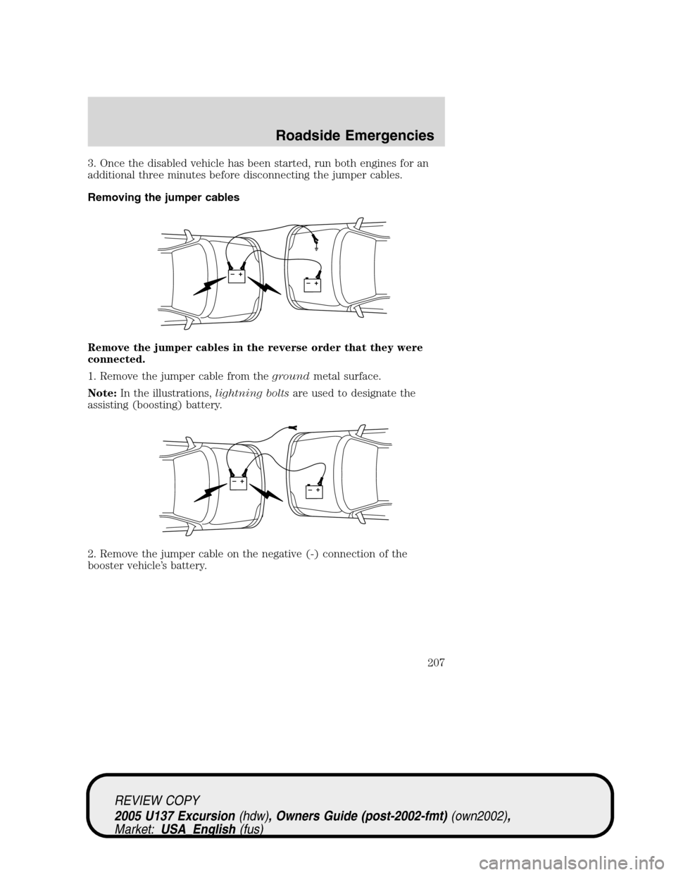
Remove the jumper cables in the reverse order that they were
connected.
1. Remove the jumper cable from thegroundmetal surface.
Note:In the illustrations,lightning boltsare used to designate the
assisting (boosting) battery.
2. Remove the jumper cable on the negative (-) connection of the
booster vehicle’s battery.
+–+–
+–+–
REVIEW COPY
2005 U137 Excursion(hdw), Owners Guide (post-2002-fmt)(own2002),
Market:USA_English(fus)
Roadside Emergencies
207
Page 208 of 280
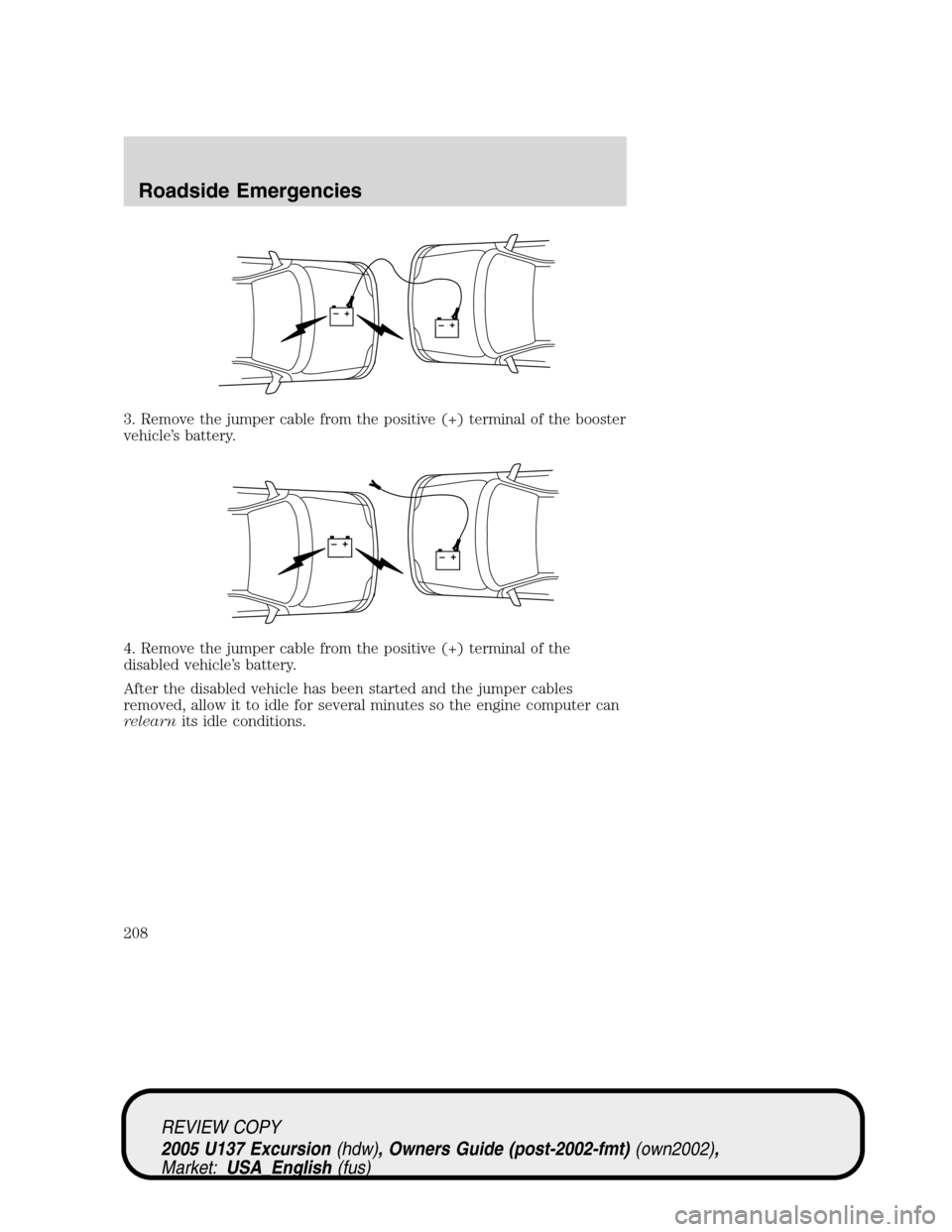
3. Remove the jumper cable from the positive (+) terminal of the booster
vehicle’s battery.
4. Remove the jumper cable from the positive (+) terminal of the
disabled vehicle’s battery.
After the disabled vehicle has been started and the jumper cables
removed, allow it to idle for several minutes so the engine computer can
relearnits idle conditions.
+–+–
+–+–
REVIEW COPY
2005 U137 Excursion(hdw), Owners Guide (post-2002-fmt)(own2002),
Market:USA_English(fus)
Roadside Emergencies
208
Page 209 of 280
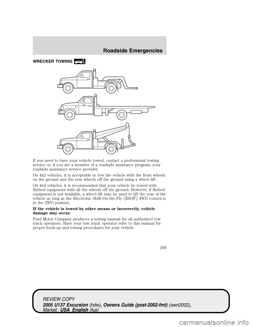
WRECKER TOWING
If you need to have your vehicle towed, contact a professional towing
service or, if you are a member of a roadside assistance program, your
roadside assistance service provider.
On 4x2 vehicles, it is acceptable to tow the vehicle with the front wheels
on the ground and the rear wheels off the ground using a wheel lift.
On 4x4 vehicles, it is recommended that your vehicle be towed with
flatbed equipment with all the wheels off the ground. However, if flatbed
equipment is not available, a wheel lift may be used to lift the rear of the
vehicle as long as the Electronic Shift-On-the-Fly (ESOF) 4WD control is
in the 2WD position.
If the vehicle is towed by other means or incorrectly, vehicle
damage may occur.
Ford Motor Company produces a towing manual for all authorized tow
truck operators. Have your tow truck operator refer to this manual for
proper hook-up and towing procedures for your vehicle.
REVIEW COPY
2005 U137 Excursion(hdw), Owners Guide (post-2002-fmt)(own2002),
Market:USA_English(fus)
Roadside Emergencies
209
Page 210 of 280
GETTING THE SERVICES YOU NEED
At home
You must take your Ford vehicle to an authorized Ford dealer for
warranty repairs. While any Ford dealership handling your vehicle line
will provide warranty service, we recommend you return to your selling
dealer who wants to ensure your continued satisfaction. Please note that
certain warranty repairs require special training and/or equipment, so not
all dealers are authorized to perform all warranty repairs. This means
that, depending on the warranty repair needed, you may have to take
your vehicle to another dealer. A reasonable time must be allowed to
perform a repair after taking your vehicle to the dealership. Repairs will
be made using Ford or Motorcraft parts, or remanufactured or other
parts that are authorized by Ford.
If you have questions or concerns, or are unsatisfied with the service you
are receiving, follow these steps:
1. Contact your Sales Representative or Service Advisor at your
selling/servicing dealership.
2. If your inquiry or concern remains unresolved, contact the Sales
Manager, Service Manager or Customer Relations Manager.
3. If you require assistance or clarification on Ford Motor Company
policies or procedures, please contact the Ford Customer Relationship
Center at the number below.
Away from home
If you own a Ford or Mercury vehicle and are away from home when
your vehicle needs service, or if you need more help than the dealership
could provide, after following the steps described above, contact the
Ford Customer Relationship Center to find an authorized dealership to
help you.
In the United States:
Ford Motor Company
Customer Relationship Center
P.O. Box 6248
Dearborn, MI 48121
1-800-392-3673 (FORD)
(TDD for the hearing impaired: 1-800-232-5952)
www.customersaskford.com
In Canada:
Customer Relationship Centre
REVIEW COPY
2005 U137 Excursion(hdw), Owners Guide (post-2002-fmt)(own2002),
Market:USA_English(fus)
Customer Assistance
Customer Assistance
210