mirror FORD EXPEDITION 1997 1.G Owners Manual
[x] Cancel search | Manufacturer: FORD, Model Year: 1997, Model line: EXPEDITION, Model: FORD EXPEDITION 1997 1.GPages: 224, PDF Size: 2.2 MB
Page 51 of 224
Compass zone adjustment
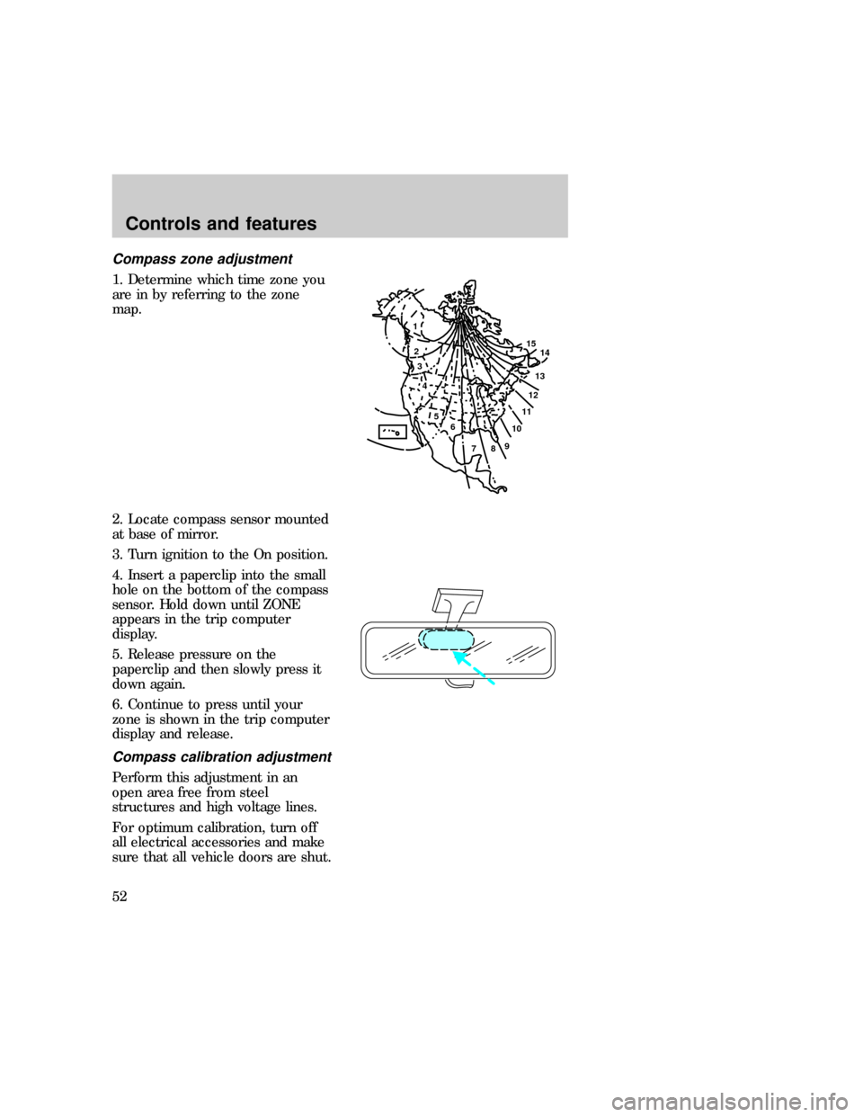
1. Determine which time zone you
are in by referring to the zone
map.
2. Locate compass sensor mounted
at base of mirror.
3. Turn ignition to the On position.
4. Insert a paperclip into the small
hole on the bottom of the compass
sensor. Hold down until ZONE
appears in the trip computer
display.
5. Release pressure on the
paperclip and then slowly press it
down again.
6. Continue to press until your
zone is shown in the trip computer
display and release.
Compass calibration adjustment
Perform this adjustment in an
open area free from steel
structures and high voltage lines.
For optimum calibration, turn off
all electrical accessories and make
sure that all vehicle doors are shut.
1
2
3
4
5
6
7891011121314 15
exd_claibration_adjust_compass
Controls and features
52
Page 52 of 224
1. Start the vehicle.
2. Locate compass sensor mounted
at base of mirror.
3. Insert a paperclip into the small
hole on the bottom of the compass
sensor. Hold down until ZONE
appears in the trip computer
display Continue to hold down
until ZONE disappears and CAL is
displayed.
4. Press and hold the MODE
control until CAL appears in the
display (approximately eight
seconds) and release.
5. Drive the vehicle slowly (less
than 5 km/h [3 mph] in circles until
CAL indicator turns off (4±5
complete circles).
6. The compass is now calibrated.
Trip computer (if equipped)
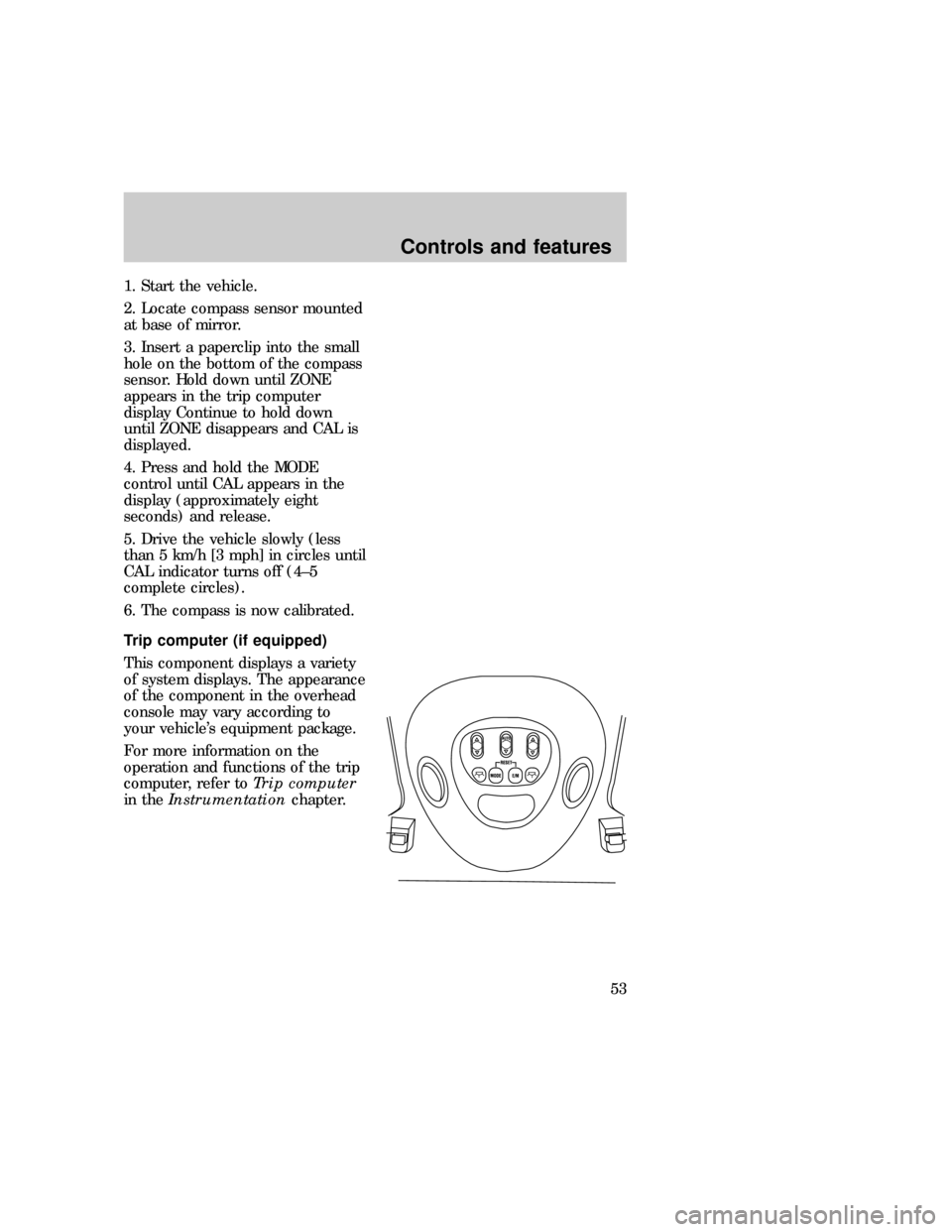
This component displays a variety
of system displays. The appearance
of the component in the overhead
console may vary according to
your vehicle's equipment package.
For more information on the
operation and functions of the trip
computer, refer toTrip computer
in theInstrumentationchapter.
exd_message_center
exd_lamps_overhead_title
Controls and features
53
Page 59 of 224
Power door locks
Driver and passenger controls
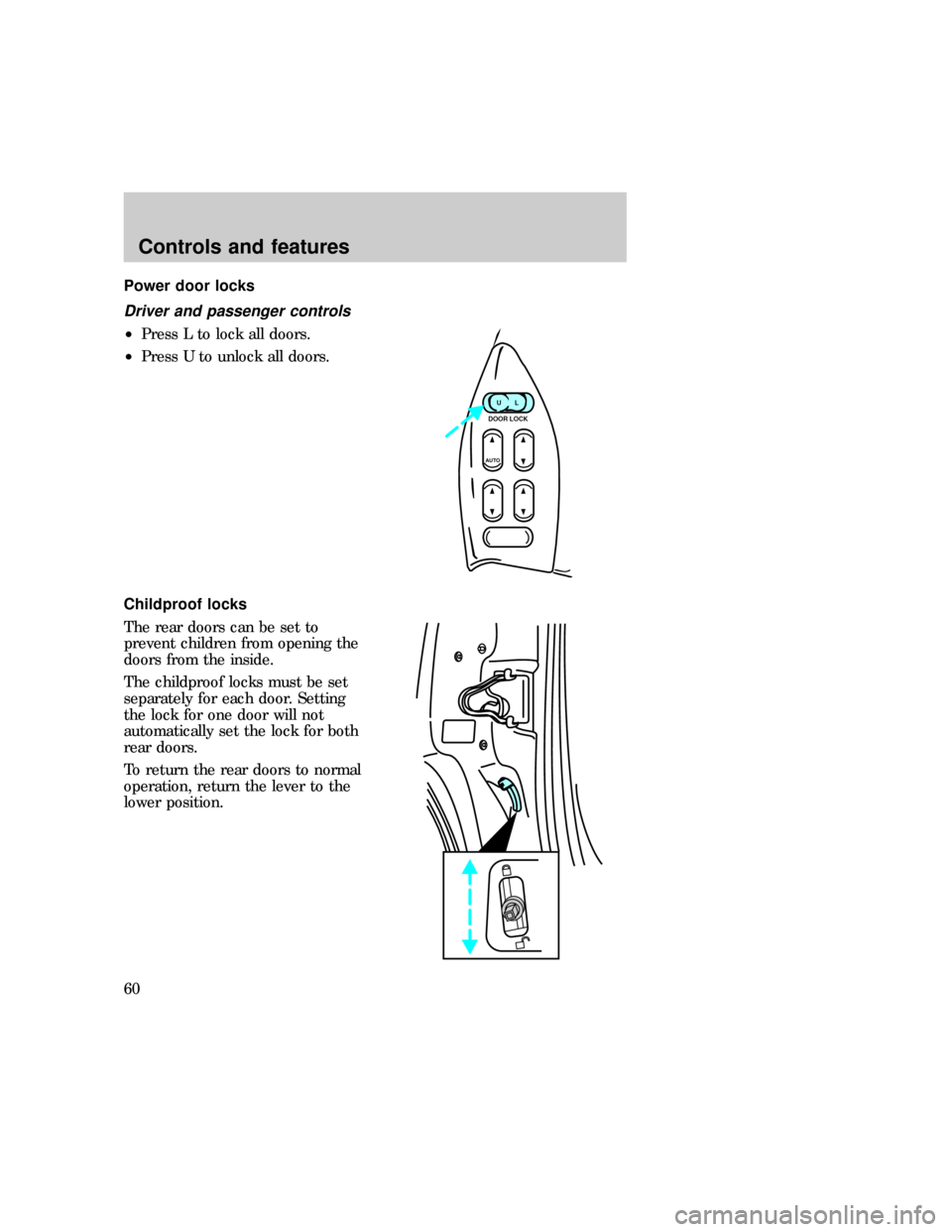
²Press L to lock all doors.
²Press U to unlock all doors.
Childproof locks
The rear doors can be set to
prevent children from opening the
doors from the inside.
The childproof locks must be set
separately for each door. Setting
the lock for one door will not
automatically set the lock for both
rear doors.
To return the rear doors to normal
operation, return the lever to the
lower position.
UL
DOOR LOCK
AUTO
exd_driver_controls exd_childproof_locks
exd_mirrors_power
Controls and features
60
Page 60 of 224
Power mirrors
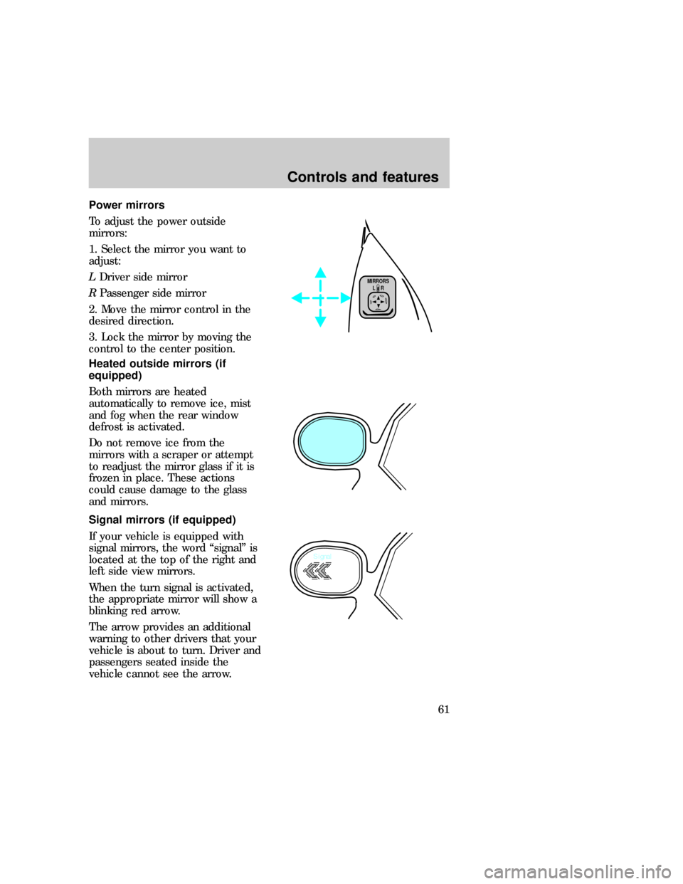
To adjust the power outside
mirrors:
1. Select the mirror you want to
adjust:
LDriver side mirror
RPassenger side mirror
2. Move the mirror control in the
desired direction.
3. Lock the mirror by moving the
control to the center position.
Heated outside mirrors (if
equipped)
Both mirrors are heated
automatically to remove ice, mist
and fog when the rear window
defrost is activated.
Do not remove ice from the
mirrors with a scraper or attempt
to readjust the mirror glass if it is
frozen in place. These actions
could cause damage to the glass
and mirrors.
Signal mirrors (if equipped)
If your vehicle is equipped with
signal mirrors, the word ªsignalº is
located at the top of the right and
left side view mirrors.
When the turn signal is activated,
the appropriate mirror will show a
blinking red arrow.
The arrow provides an additional
warning to other drivers that your
vehicle is about to turn. Driver and
passengers seated inside the
vehicle cannot see the arrow.
L MIRRORS
R
Signal
exd_heated_mirrors
exd_signal_mirrors
exd_liftgate_controls
Controls and features
61
Page 137 of 224

Slot number Fuse
amperage
ratingCircuits protected
13 30 amp Auxiliary blower
14 60 amp Four wheel anti-lock brake system
(4WABS)
15 50 amp Air suspension compressor
16 40 amp Trailer tow battery charge, engine
minifuse box fuse #2, engine minifuse
box fuse #4
17 30 amp Four-wheel drive (4WD) transfer case
motor and clutch
18 30 amp Driver power seat
19 20 amp Fuel pump
20 50 amp Junction box ignition switched feed
21 50 amp Junction box ignition switched feed
22 50 amp Junction box battery feed
23 40 amp Front blower
24 30 amp Powertrain control module power
25 30 C.B. Windows
26 - not used
27 40 amp Heated backlite and mirrors
28 30 amp Trailer tow electric brake
29 30 amp Hybrid fan, moon roof, flip windows
Slot number Description
1 - not used
2 - PCM diode
Slot number Description
1 - Windshield wipers high/low speed
2 - Windshield wipers run/park
3 - Front washer pump relay
4 - Fuel pump relay
Roadside emergencies
138
Page 140 of 224
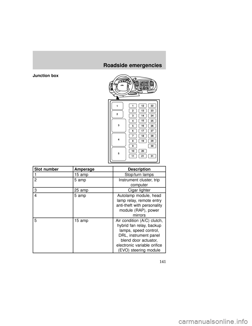
Junction box
Slot number Amperage Description
1 15 amp Stop/turn lamps
2 5 amp Instrument cluster, trip
computer
3 25 amp Cigar lighter
4 5 amp Autolamp module, head
lamp relay, remote entry
anti-theft with personality
module (RAP), power
mirrors
5 15 amp Air condition (A/C) clutch,
hybrid fan relay, backup
lamps, speed control,
DRL, instrument panel
blend door actuator,
electronic variable orifice
(EVO) steering module
1
1
2
3
4
512 22
21323
31424
4
16 15
25
526
61727
71828
81929
11 21 31930
10 20
exd_junction_box
Roadside emergencies
141
Page 141 of 224

Slot number Amperage Description
6 5 amp Generic electronic module
(GEM), shift interlock, air
suspension module,
heated backlite (HBL)
relay, steering sensor, trip
computer, compass
7 5 amp Console blower, auxiliary
blower relay coil
8 5 amp GEM, radio, RAP module
9 - Not used
10 - Not used
11 30 amp Front wiper motor, washer
motor
12 5 amp OBDII scan tool connector
13 15 amp Brake on/off switch, brake
pressure switch
14 15 amp Interior lamps, delayed
accessory relay, rear wiper
relays
15 5 amp GEM, passive anti-theft
system (PATS) module
16 20 amp High beam headlamps,
high beam indicator
17 10 amp Heated mirrors, heated
mirror switch
18 5 amp Instrument and switch
illumination
19 10 amp Airbag diagnostic monitor,
instrument cluster
20 5 amp GEM, air suspension
module
21 15 amp Starter relay, junction box
fuse #20
Roadside emergencies
142