air condition FORD EXPEDITION 1998 1.G Owners Manual
[x] Cancel search | Manufacturer: FORD, Model Year: 1998, Model line: EXPEDITION, Model: FORD EXPEDITION 1998 1.GPages: 216, PDF Size: 1.51 MB
Page 8 of 216
If theCheck Enginelight remains
on, have your vehicle serviced at
the first available opportunity.
Light is blinking:
Engine misfire is occurring which
could damage your catalytic
converter. You should drive in a
moderate fashion (avoid heavy
acceleration and deceleration) and
have your vehicle serviced at the
first available opportunity.
Under engine misfire
conditions, excessive
exhaust temperatures could
damage the catalytic converter,
the fuel system, interior floor
coverings or other vehicle
components, possibly causing a
fire.
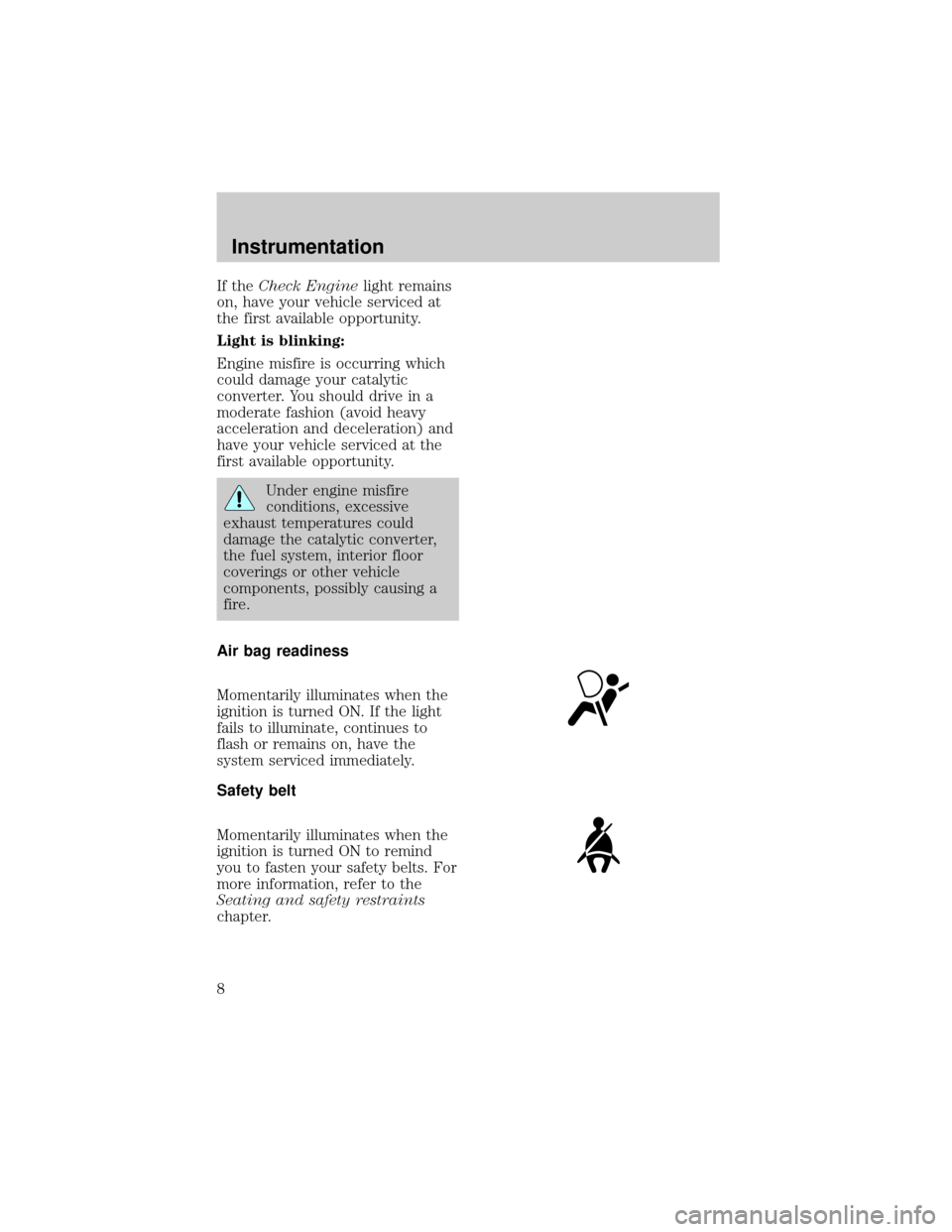
Air bag readiness
Momentarily illuminates when the
ignition is turned ON. If the light
fails to illuminate, continues to
flash or remains on, have the
system serviced immediately.
Safety belt
Momentarily illuminates when the
ignition is turned ON to remind
you to fasten your safety belts. For
more information, refer to the
Seating and safety restraints
chapter.
Instrumentation
8
Page 23 of 216
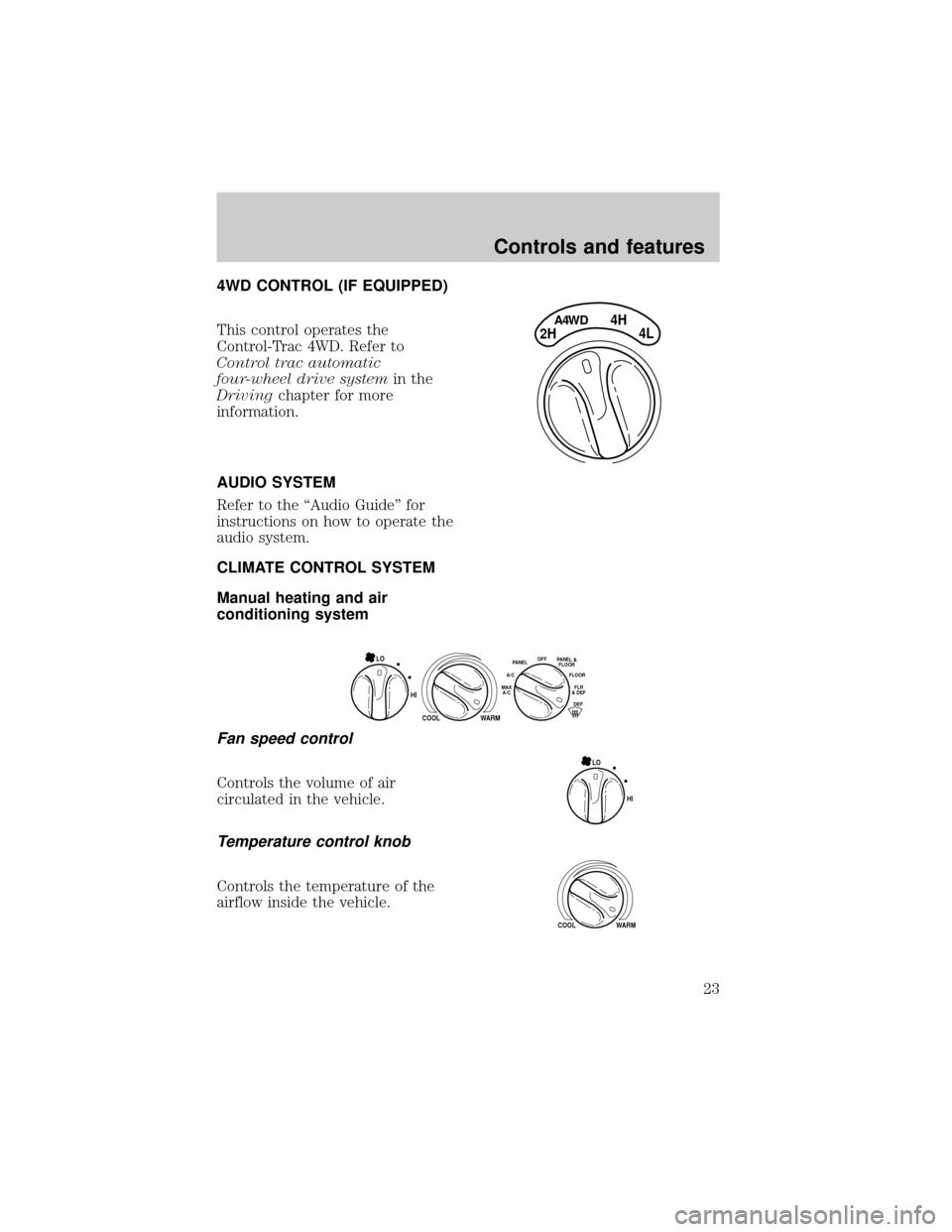
4WD CONTROL (IF EQUIPPED)
This control operates the
Control-Trac 4WD. Refer to
Control trac automatic
four-wheel drive systemin the
Drivingchapter for more
information.
AUDIO SYSTEM
Refer to the ªAudio Guideº for
instructions on how to operate the
audio system.
CLIMATE CONTROL SYSTEM
Manual heating and air
conditioning system
Fan speed control
Controls the volume of air
circulated in the vehicle.
Temperature control knob
Controls the temperature of the
airflow inside the vehicle.
4H
2HA4WD4L
HI
COOL WARM
OFFPANELFLOOR
DEFFLR
& DEF A/C
MAX
A/CPANEL &
FLOOR
LO
HI LO
COOL WARM
Controls and features
23
Page 24 of 216

Mode selector control
Controls the direction of the
airflow to the inside of the vehicle.
The air conditioning compressor
will operate in all modes except
PANEL and FLOOR. However, the
air conditioning will only function
if the outside temperature is about
10ÉC (50ÉF) or above.
Since the air conditioner removes
considerable moisture from the air
during operation, it is normal if
clear water drips on the ground
under the air conditioner drain
while the system is working and
even after you have stopped the
vehicle.
Under normal conditions, your
vehicle's climate control system
should be left in any position other
than MAX A/C or OFF when the
vehicle is parked. This allows the
vehicle to ªbreatheº through the
outside air inlet duct.
²MAX A/C-Uses recirculated air
to cool the vehicle. MAX A/C is
noisier than A/C but more
economical and will cool the
inside of the vehicle faster.
Airflow will be from the
instrument panel registers. This
mode can also be used to
prevent undesirable odors from
entering the vehicle.
²A/C-Uses outside air to cool the
OFFPANEL
A/CFLOOR
DEFFLR
& DEFMAX
A/C
PANEL &
FLOOR
Controls and features
24
Page 25 of 216

vehicle. It is quieter than MAX
A/C but not as economical.
Airflow will be from the
instrument panel registers.
²PANEL-Distributes outside air
through the instrument panel
registers. However, the air will
not be cooled below the outside
temperature because the air
conditioning does not operate in
this mode.
²OFF-Outside air is shut out and
the fan will not operate. For
short periods of time only, use
this mode to prevent
undesirable odors from entering
the vehicle.
²PANEL & FLOOR-Distributes
outside air through the
instrument panel registers and
the floor ducts. Heating and air
conditioning capabilities are
provided in this mode. For
added customer comfort, when
the temperature control knob is
anywhere in between the full
hot and full cold positions, the
air distributed through the floor
ducts will be slightly warmer
than the air sent to the
instrument panel registers.
²FLOOR-Allows for maximum
heating by distributing outside
air through the floor ducts.
However, the air will not be
cooled below the outside
temperature because the air
conditioning does not operate in
this mode.
Controls and features
25
Page 26 of 216

²FLR & DEF-Distributes outside
air through the windshield
defroster ducts and the floor
ducts. Heating and air
conditioning capabilities are
provided in this mode. For
added customer comfort, the air
distributed through the floor
ducts will be slightly warmer
than the air sent to the
windshield defroster ducts. If
the temperature is about 10ÉC
(50ÉF) or higher, the air
conditioner will automatically
dehumidify the air to prevent
fogging.
²DEF
-Distributes outside
air through the windshield
defroster ducts. It can be used
to clear ice or fog from the
windshield. If the temperature is
about 10ÉC (50ÉF) or higher, the
air conditioner will automatically
dehumidify the air to prevent
fogging.
Operating tips
²In humid weather, select DEF
before driving. This will
prevent your windshield from
fogging. After a few minutes,
select any desired position.
²To prevent humidity buildup
inside the vehicle, don't drive
with the climate control system
in the OFF position.
²Don't put objects under the
front seat that will interfere with
the airflow to the back seats (if
equipped).
Controls and features
26
Page 27 of 216
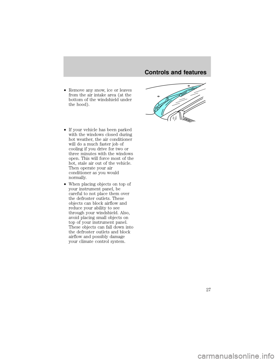
²Remove any snow, ice or leaves
from the air intake area (at the
bottom of the windshield under
the hood).
²If your vehicle has been parked
with the windows closed during
hot weather, the air conditioner
will do a much faster job of
cooling if you drive for two or
three minutes with the windows
open. This will force most of the
hot, stale air out of the vehicle.
Then operate your air
conditioner as you would
normally.
²When placing objects on top of
your instrument panel, be
careful to not place them over
the defroster outlets. These
objects can block airflow and
reduce your ability to see
through your windshield. Also,
avoid placing small objects on
top of your instrument panel.
These objects can fall down into
the defroster outlets and block
airflow and possibly damage
your climate control system.
Controls and features
27
Page 44 of 216
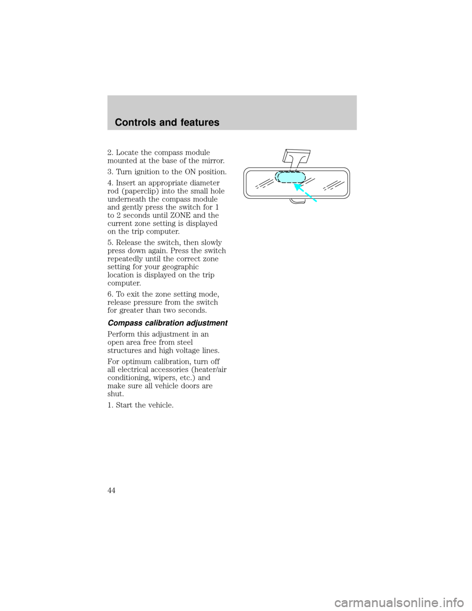
2. Locate the compass module
mounted at the base of the mirror.
3. Turn ignition to the ON position.
4. Insert an appropriate diameter
rod (paperclip) into the small hole
underneath the compass module
and gently press the switch for 1
to 2 seconds until ZONE and the
current zone setting is displayed
on the trip computer.
5. Release the switch, then slowly
press down again. Press the switch
repeatedly until the correct zone
setting for your geographic
location is displayed on the trip
computer.
6. To exit the zone setting mode,
release pressure from the switch
for greater than two seconds.
Compass calibration adjustment
Perform this adjustment in an
open area free from steel
structures and high voltage lines.
For optimum calibration, turn off
all electrical accessories (heater/air
conditioning, wipers, etc.) and
make sure all vehicle doors are
shut.
1. Start the vehicle.
Controls and features
44
Page 78 of 216
Safety belt assemblies not in use
during a collision should also be
inspected and replaced if either
damage or improper operation is
noted.
Failure to replace the
safety belt assembly under
the above conditions could result
in severe personal injuries in the
event of a collision.
Refer toCleaning and
maintaining the safety beltsin
theMaintenance and care
section.
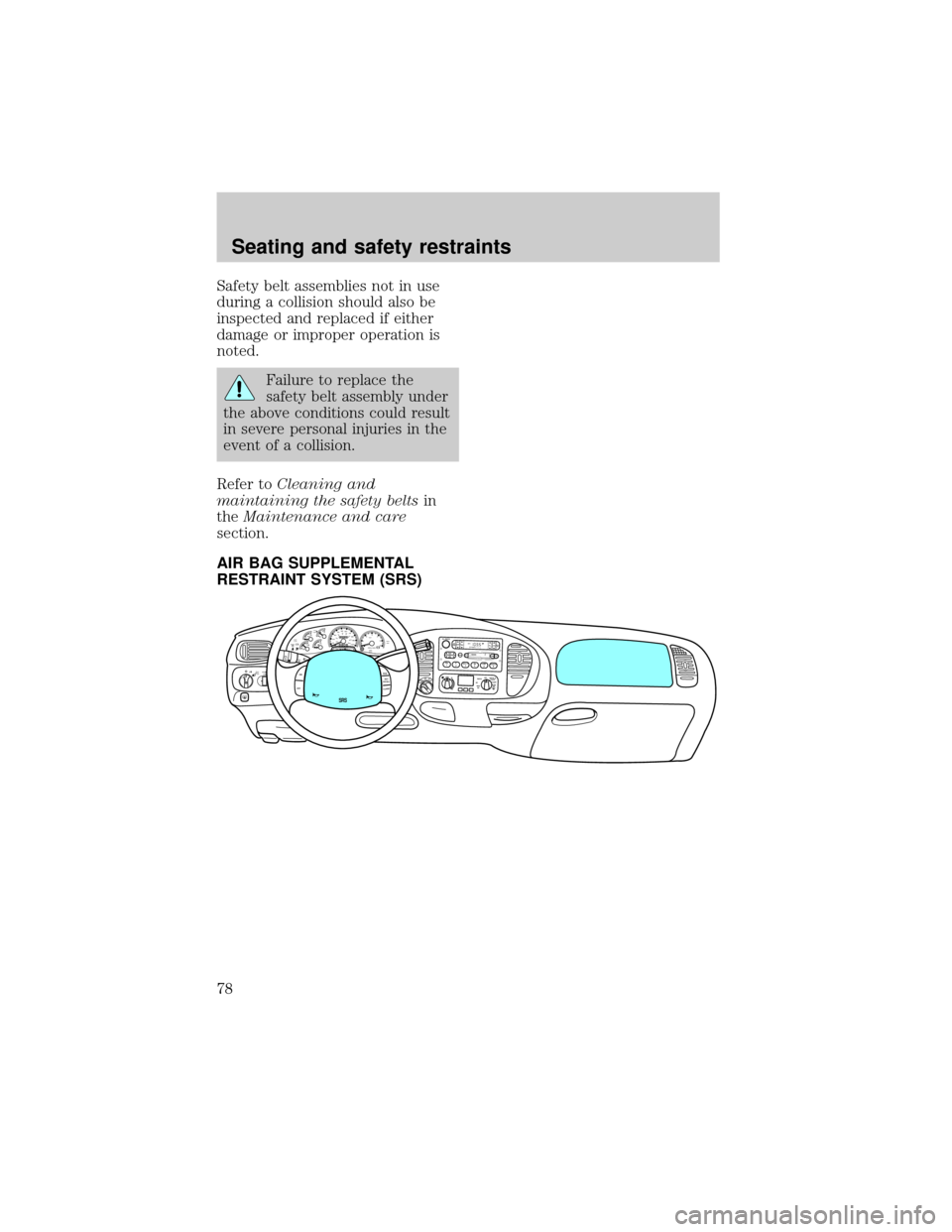
AIR BAG SUPPLEMENTAL
RESTRAINT SYSTEM (SRS)
FOR
SCANEJ
REWFF SIDE 1-2COMPSHUFFLETAPECDDISCSBASS
TREB
BAL
FADEAUTO
SETVOL - PUSH ONS
E
E
KTUNEAM
FM
12 3456fwDOLBY B NRFM1S
TDOOR
AJAR
BRAKEF
E
H H
18
820
10304050
60
70
80
90
10020 406080
100
120
140
160
MPH km/h00000000
012PRN 21RPMx1000CHECK
ENGINE THEFT3
4
5
6CHECK
SUSPLOW
FUEL
ABS
PPULL
FOGPANEL
DIM4H
A4WD4LFLOOR
PANELLO
HICOOLW
ARMDEF FLR&
DEF PANEL &
FLOOR OFFPAN
ELLO
HIFLR&
DEF PAN
EL &
FLOOR OFF
M
AX
AC AC FLOORFAN
OVERDRIVE
SRS
ON
OFFRES
SET
ACCELCOAST
Seating and safety restraints
78
Page 82 of 216
If the air bag is inflated,
the air bag will not
function again and must be
replaced immediately.Ifthe
air bag is not replaced, the
unrepaired area will increase the
risk of injury in a collision.
The SRS consists of:
²driver and passenger air bag
modules (which include the
inflators and air bags),
²one or more impact and safing
sensors,
²a readiness light and tone
²and the electrical wiring which
connects the components.
The diagnostic module monitors its
own internal circuits and the
supplemental air bag electrical
system warning (including the
impact sensors), the system wiring,
the air bag system readiness light,
the air bag back up power and the
air bag ignitors.
Determining if the system is
operational
The SRS uses a readiness light in
the instrument cluster or a tone to
indicate the condition of the
system. Refer to theAir bag
readinesssection in the
Instrumentationchapter. Routine
maintenance of the air bag is not
required.
Seating and safety restraints
82
Page 97 of 216

If you ever smell exhaust
fumes of any kind inside
your vehicle, have your dealer
inspect and fix your vehicle
immediately. Do not drive if you
smell exhaust fumes. These
fumes are harmful and could kill
you.
Have the exhaust and body
ventilation systems checked
whenever:
²the vehicle is raised for service
²the sound of the exhaust system
changes
²the vehicle has been damaged in
a collision
Important ventilating
information
If the engine is idling while the
vehicle is stopped in an open area
for long periods of time, open the
windows at least 2.5 cm (one
inch).
Adjust the heating or air
conditioning (if equipped) to bring
in fresh air.
Improve vehicle ventilation by
keeping all air inlet vents clear of
snow, leaves and other debris.
Starting
97