trip computer FORD EXPEDITION 1998 1.G Owners Manual
[x] Cancel search | Manufacturer: FORD, Model Year: 1998, Model line: EXPEDITION, Model: FORD EXPEDITION 1998 1.GPages: 216, PDF Size: 1.51 MB
Page 16 of 216
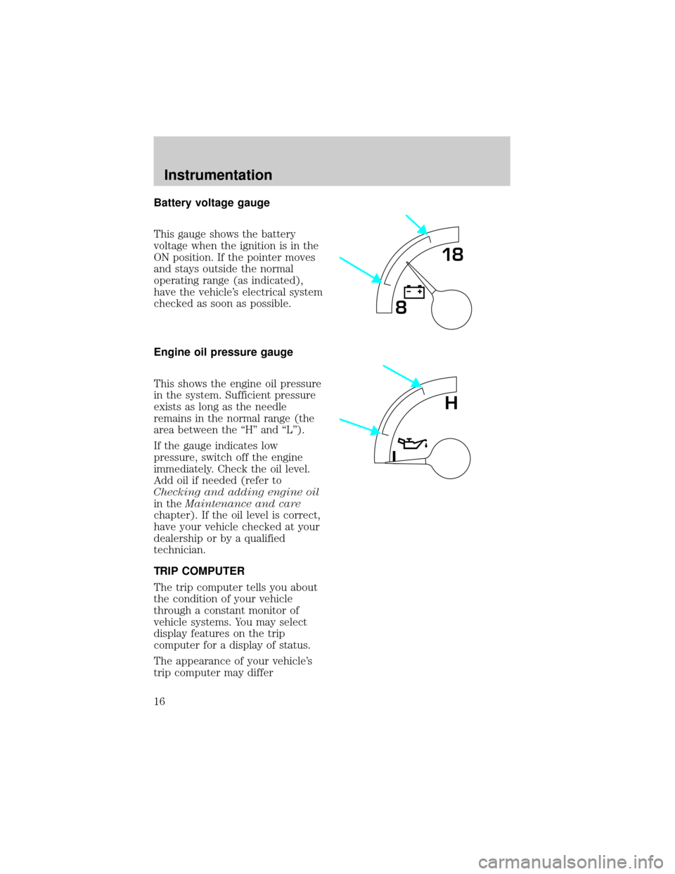
Battery voltage gauge
This gauge shows the battery
voltage when the ignition is in the
ON position. If the pointer moves
and stays outside the normal
operating range (as indicated),
have the vehicle's electrical system
checked as soon as possible.
Engine oil pressure gauge
This shows the engine oil pressure
in the system. Sufficient pressure
exists as long as the needle
remains in the normal range (the
area between the ªHº and ªLº).
If the gauge indicates low
pressure, switch off the engine
immediately. Check the oil level.
Add oil if needed (refer to
Checking and adding engine oil
in theMaintenance and care
chapter). If the oil level is correct,
have your vehicle checked at your
dealership or by a qualified
technician.
TRIP COMPUTER
The trip computer tells you about
the condition of your vehicle
through a constant monitor of
vehicle systems. You may select
display features on the trip
computer for a display of status.
The appearance of your vehicle's
trip computer may differ
818
L
H
Instrumentation
16
Page 17 of 216
depending on your vehicle's option
package, but the functions are the
same.
The trip computer only works
when the ignition is in the ON
position. Trip computer features
follow:
Selectable features
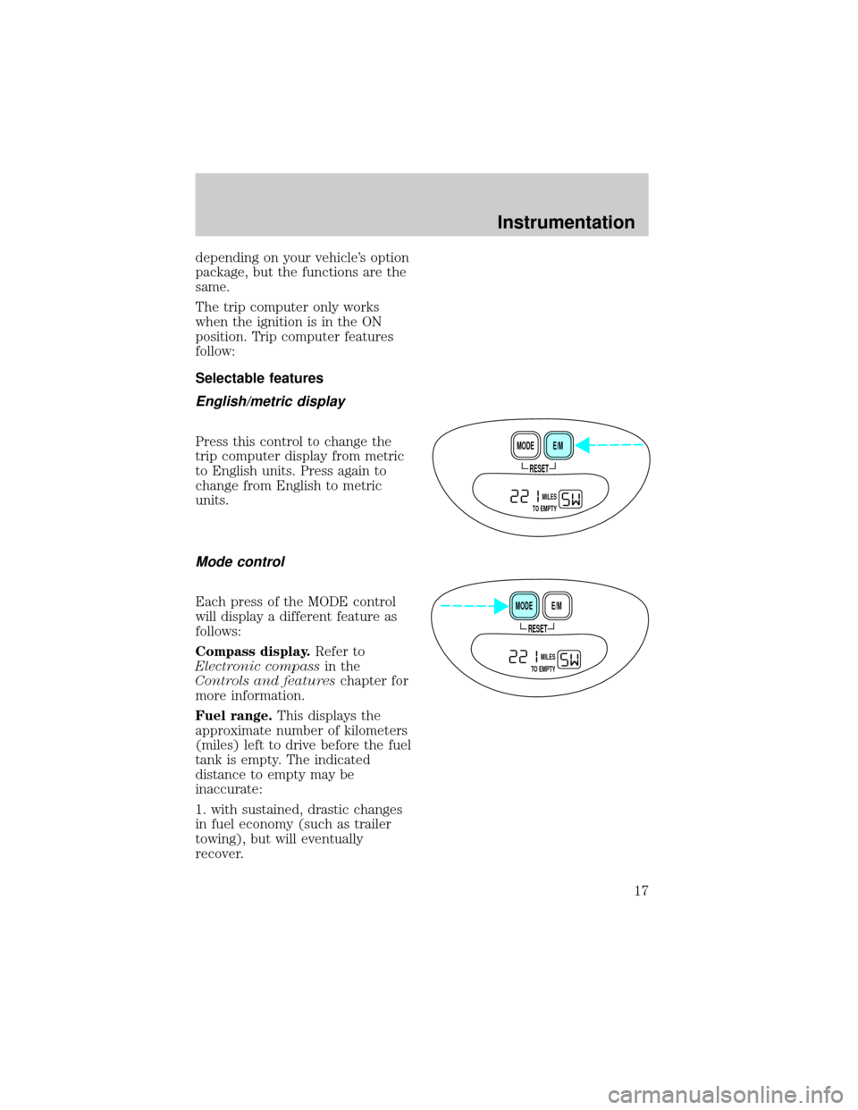
English/metric display
Press this control to change the
trip computer display from metric
to English units. Press again to
change from English to metric
units.
Mode control
Each press of the MODE control
will display a different feature as
follows:
Compass display.Refer to
Electronic compassin the
Controls and featureschapter for
more information.
Fuel range.This displays the
approximate number of kilometers
(miles) left to drive before the fuel
tank is empty. The indicated
distance to empty may be
inaccurate:
1. with sustained, drastic changes
in fuel economy (such as trailer
towing), but will eventually
recover.
RESET
E/M MODE
MILES
TO EMPTY
RESET
E/M MODE
MILES
TO EMPTY
Instrumentation
17
Page 19 of 216
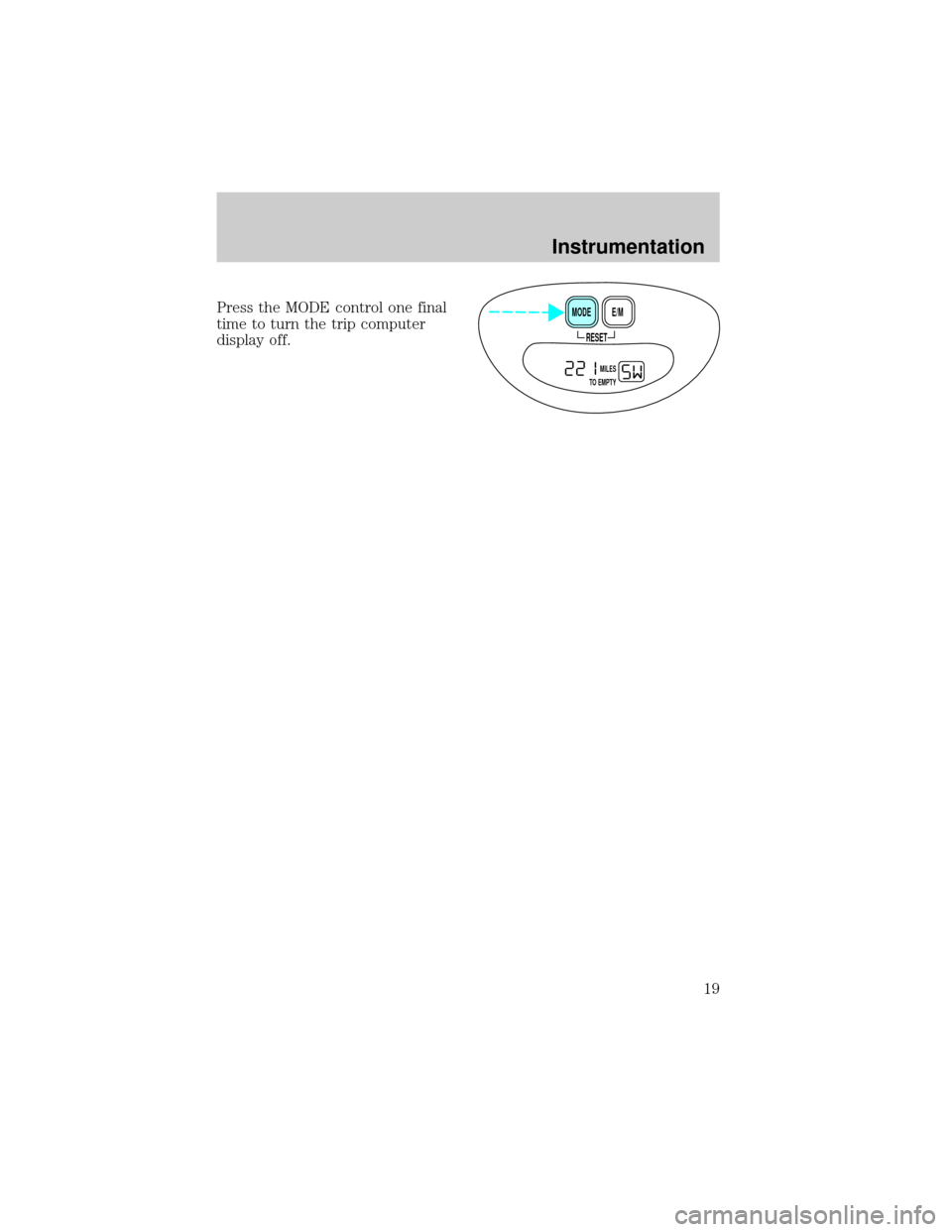
Press the MODE control one final
time to turn the trip computer
display off.
RESET
E/M MODE
MILES
TO EMPTY
Instrumentation
19
Page 44 of 216
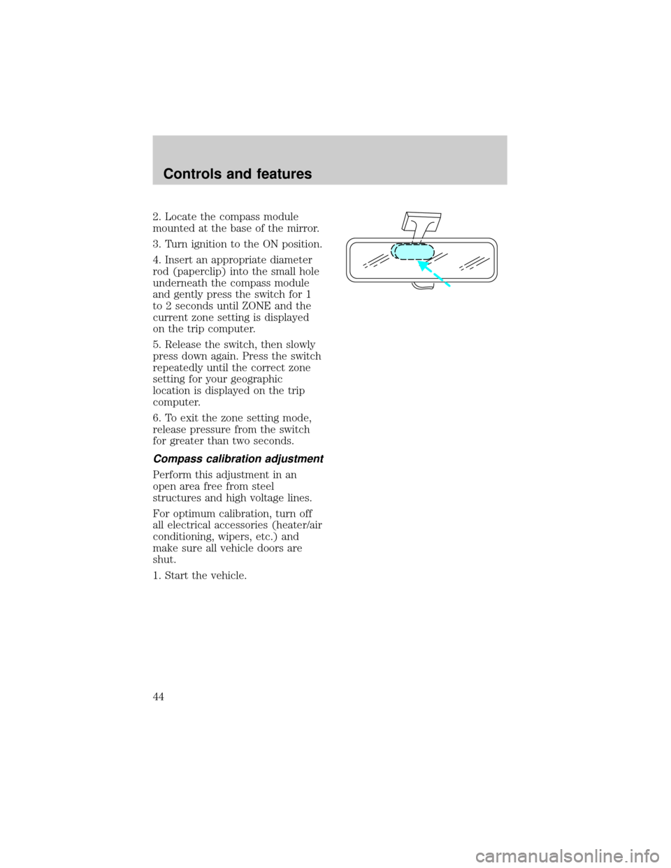
2. Locate the compass module
mounted at the base of the mirror.
3. Turn ignition to the ON position.
4. Insert an appropriate diameter
rod (paperclip) into the small hole
underneath the compass module
and gently press the switch for 1
to 2 seconds until ZONE and the
current zone setting is displayed
on the trip computer.
5. Release the switch, then slowly
press down again. Press the switch
repeatedly until the correct zone
setting for your geographic
location is displayed on the trip
computer.
6. To exit the zone setting mode,
release pressure from the switch
for greater than two seconds.
Compass calibration adjustment
Perform this adjustment in an
open area free from steel
structures and high voltage lines.
For optimum calibration, turn off
all electrical accessories (heater/air
conditioning, wipers, etc.) and
make sure all vehicle doors are
shut.
1. Start the vehicle.
Controls and features
44
Page 45 of 216
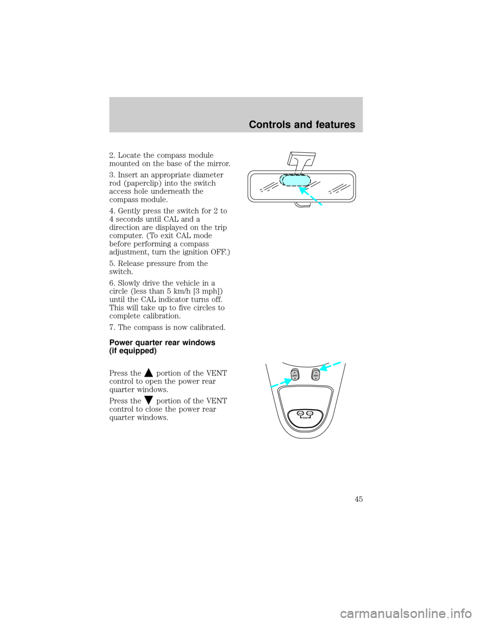
2. Locate the compass module
mounted on the base of the mirror.
3. Insert an appropriate diameter
rod (paperclip) into the switch
access hole underneath the
compass module.
4. Gently press the switch for 2 to
4 seconds until CAL and a
direction are displayed on the trip
computer. (To exit CAL mode
before performing a compass
adjustment, turn the ignition OFF.)
5. Release pressure from the
switch.
6. Slowly drive the vehicle in a
circle (less than 5 km/h [3 mph])
until the CAL indicator turns off.
This will take up to five circles to
complete calibration.
7. The compass is now calibrated.
Power quarter rear windows
(if equipped)
Press the
portion of the VENT
control to open the power rear
quarter windows.
Press the
portion of the VENT
control to close the power rear
quarter windows.
RESET
VENTVENT
MODE E/M
Controls and features
45
Page 130 of 216
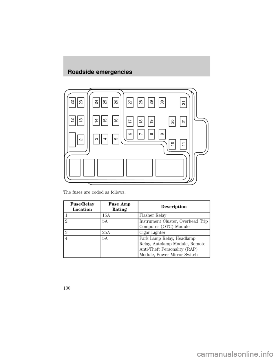
The fuses are coded as follows.
Fuse/Relay
LocationFuse Amp
RatingDescription
1 15A Flasher Relay
2 5A Instrument Cluster, Overhead Trip
Computer (OTC) Module
3 25A Cigar Lighter
4 5A Park Lamp Relay, Headlamp
Relay, Autolamp Module, Remote
Anti-Theft Personality (RAP)
Module, Power Mirror Switch
12 22
21323
617 27
718 28
819 29
930
20
31 21 11 10
31424
41525
51626
Roadside emergencies
130
Page 131 of 216
Fuse/Relay
LocationFuse Amp
RatingDescription
5 15A Digital Transmission Range (DTR)
Sensor, Daytime Running Lamps
(DRL) Module, Speed Control
Servo/Amplifier Assembly,
Heater-A/C Control Assembly,
Blend Door Actuator, Electronic
Variable Orifice (EVO) Module
6 5A Shift Lock Actuator, Generic
Electronic Module (GEM), 4
Wheel Air Suspension (4WAS)
Module, Compass Sensor, Steering
Wheel Rotation Sensor, Heated
Grid Relay, Overhead Trip
Computer (OTC) Module
7 5A Auxiliary A/C Relay, Console
Blower Motor
8 5A Radio, Main Light Switch, Remote
Anti-Theft Personality (RAP)
Module
9 Ð Not Used
10 Ð Not Used
11 30A Washer Pump Relay, Wiper
Run/Park Relay, Wiper Hi/Lo
Relay, Windshield Wiper Motor,
Rear Wiper Pump Relay
12 5A Data Link Connector (DLC)
13 15A Brake On/Off (BOO) Switch,
Brake Pressure Switch
14 15A Battery Saver Relay, Interior
Lamp Relay
15 5A Generic Electronic Module
(GEM), Passive Anti-Theft System
(PATS) Module
Roadside emergencies
131