battery location FORD EXPEDITION 1999 1.G Owners Manual
[x] Cancel search | Manufacturer: FORD, Model Year: 1999, Model line: EXPEDITION, Model: FORD EXPEDITION 1999 1.GPages: 216, PDF Size: 1.8 MB
Page 132 of 216
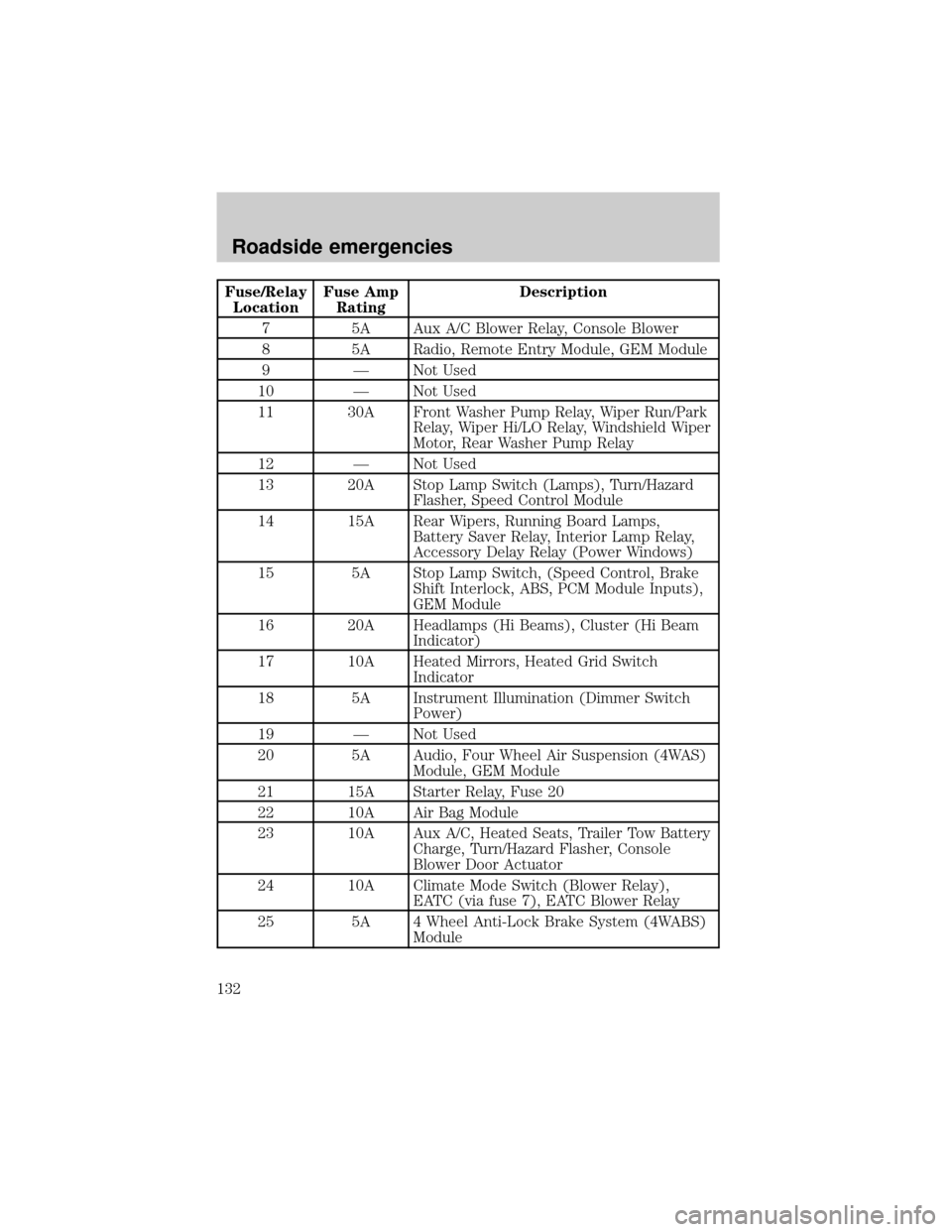
Fuse/Relay
LocationFuse Amp
RatingDescription
7 5A Aux A/C Blower Relay, Console Blower
8 5A Radio, Remote Entry Module, GEM Module
9 Ð Not Used
10 Ð Not Used
11 30A Front Washer Pump Relay, Wiper Run/Park
Relay, Wiper Hi/LO Relay, Windshield Wiper
Motor, Rear Washer Pump Relay
12 Ð Not Used
13 20A Stop Lamp Switch (Lamps), Turn/Hazard
Flasher, Speed Control Module
14 15A Rear Wipers, Running Board Lamps,
Battery Saver Relay, Interior Lamp Relay,
Accessory Delay Relay (Power Windows)
15 5A Stop Lamp Switch, (Speed Control, Brake
Shift Interlock, ABS, PCM Module Inputs),
GEM Module
16 20A Headlamps (Hi Beams), Cluster (Hi Beam
Indicator)
17 10A Heated Mirrors, Heated Grid Switch
Indicator
18 5A Instrument Illumination (Dimmer Switch
Power)
19 Ð Not Used
20 5A Audio, Four Wheel Air Suspension (4WAS)
Module, GEM Module
21 15A Starter Relay, Fuse 20
22 10A Air Bag Module
23 10A Aux A/C, Heated Seats, Trailer Tow Battery
Charge, Turn/Hazard Flasher, Console
Blower Door Actuator
24 10A Climate Mode Switch (Blower Relay),
EATC (via fuse 7), EATC Blower Relay
25 5A 4 Wheel Anti-Lock Brake System (4WABS)
Module
Roadside emergencies
132
Page 133 of 216
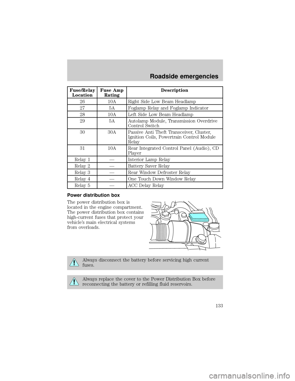
Fuse/Relay
LocationFuse Amp
RatingDescription
26 10A Right Side Low Beam Headlamp
27 5A Foglamp Relay and Foglamp Indicator
28 10A Left Side Low Beam Headlamp
29 5A Autolamp Module, Transmission Overdrive
Control Switch
30 30A Passive Anti Theft Transceiver, Cluster,
Ignition Coils, Powertrain Control Module
Relay
31 10A Rear Integrated Control Panel (Audio), CD
Player
Relay 1 Ð Interior Lamp Relay
Relay 2 Ð Battery Saver Relay
Relay 3 Ð Rear Window Defroster Relay
Relay 4 Ð One Touch Down Window Relay
Relay 5 Ð ACC Delay Relay
Power distribution box
The power distribution box is
located in the engine compartment.
The power distribution box contains
high-current fuses that protect your
vehicle's main electrical systems
from overloads.
Always disconnect the battery before servicing high current
fuses.
Always replace the cover to the Power Distribution Box before
reconnecting the battery or refilling fluid reservoirs.
Roadside emergencies
133
Page 134 of 216
If the battery has been disconnected and reconnected, refer to the
Batterysection of theMaintenance and Carechapter.
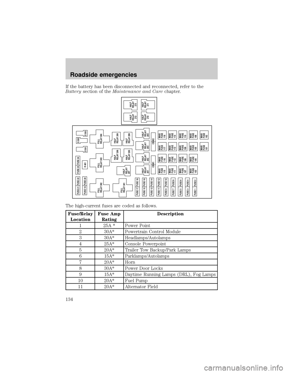
The high-current fuses are coded as follows.
Fuse/Relay
LocationFuse Amp
RatingDescription
1 25A * Power Point
2 30A* Powertrain Control Module
3 30A* Headlamps/Autolamps
4 25A* Console Powerpoint
5 20A* Trailer Tow Backup/Park Lamps
6 15A* Parklamps/Autolamps
7 20A* Horn
8 30A* Power Door Locks
9 15A* Daytime Running Lamps (DRL), Fog Lamps
10 20A* Fuel Pump
11 20A* Alternator Field
MAXI
FUSE
115MAXI
FUSE
116MAXI
FUSE
117
MAXI
FUSE
118
MAXI
FUSE
111MAXI
FUSE
112MAXI
FUSE
113
MAXI
FUSE
114
MAXI
FUSE
107MAXI
FUSE
108MAXI
FUSE
109
MAXI
FUSE
110
MAXI
FUSE
103MAXI
FUSE
104MAXI
FUSE
105
MAXI
FUSE
106
MAXI
FUSE
101MAXI
FUSE
102 CB601 CB602 FUSE 17 FUSE 18FUSE 21 FUSE 22
FUSE 19 FUSE 20FUSE 23
FULL
RELAY 302R 401
D 501 FUSE 24
FUSE 15 FUSE 16
FUSE 13 FUSE 14
FUSE 11 FUSE 12
FUSE 9 FUSE 10
FUSE 7 FUSE 8
FUSE 5 FUSE 6
FUSE 3 FUSE 4
FUSE 1 FUSE 2
D 503 D 502
FULL
RELAY 301HALF
RELAY
207
FULL
RELAY 303
FULL
RELAY 304
HALF
RELAY
201
HALF
RELAY
202HALF
RELAY 208
HALF
RELAY 209
HALF
RELAY 205
HALF
RELAY 206
HALF
RELAY
203
HALF
RELAY
204
HALF
RELAY
212
HALF
RELAY
210HALF
RELAY
213
HALF
RELAY
211
Roadside emergencies
134
Page 135 of 216
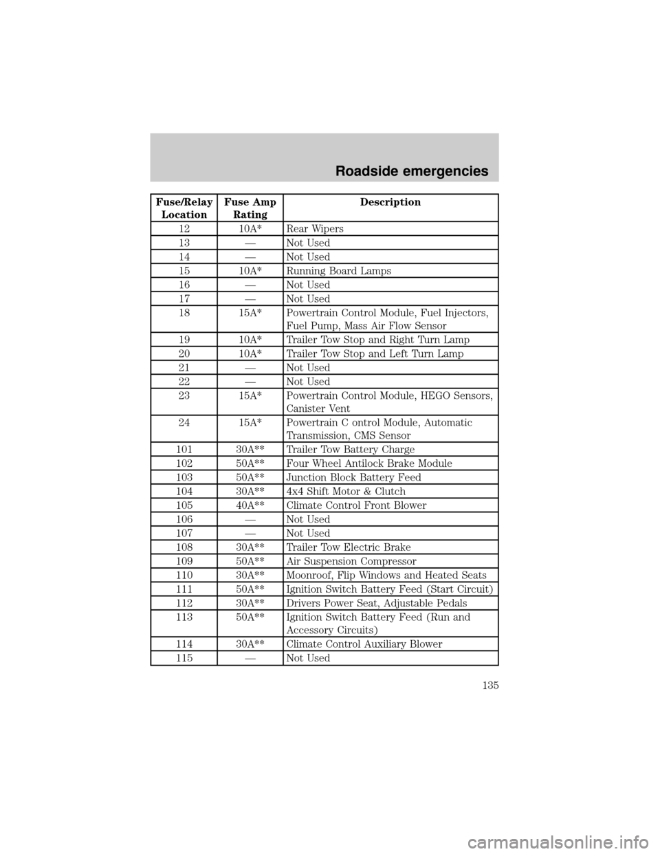
Fuse/Relay
LocationFuse Amp
RatingDescription
12 10A* Rear Wipers
13 Ð Not Used
14 Ð Not Used
15 10A* Running Board Lamps
16 Ð Not Used
17 Ð Not Used
18 15A* Powertrain Control Module, Fuel Injectors,
Fuel Pump, Mass Air Flow Sensor
19 10A* Trailer Tow Stop and Right Turn Lamp
20 10A* Trailer Tow Stop and Left Turn Lamp
21 Ð Not Used
22 Ð Not Used
23 15A* Powertrain Control Module, HEGO Sensors,
Canister Vent
24 15A* Powertrain C ontrol Module, Automatic
Transmission, CMS Sensor
101 30A** Trailer Tow Battery Charge
102 50A** Four Wheel Antilock Brake Module
103 50A** Junction Block Battery Feed
104 30A** 4x4 Shift Motor & Clutch
105 40A** Climate Control Front Blower
106 Ð Not Used
107 Ð Not Used
108 30A** Trailer Tow Electric Brake
109 50A** Air Suspension Compressor
110 30A** Moonroof, Flip Windows and Heated Seats
111 50A** Ignition Switch Battery Feed (Start Circuit)
112 30A** Drivers Power Seat, Adjustable Pedals
113 50A** Ignition Switch Battery Feed (Run and
Accessory Circuits)
114 30A** Climate Control Auxiliary Blower
115 Ð Not Used
Roadside emergencies
135
Page 136 of 216
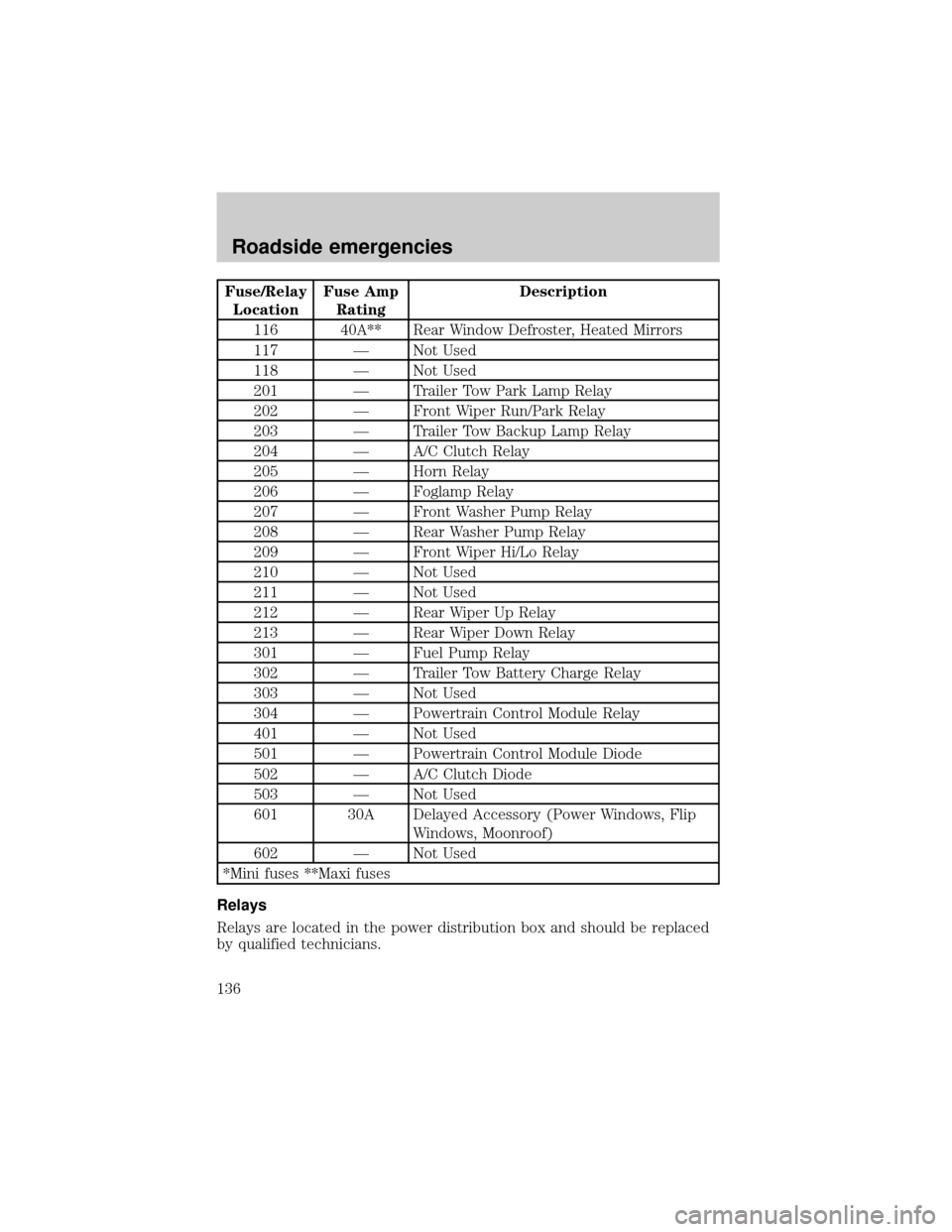
Fuse/Relay
LocationFuse Amp
RatingDescription
116 40A** Rear Window Defroster, Heated Mirrors
117 Ð Not Used
118 Ð Not Used
201 Ð Trailer Tow Park Lamp Relay
202 Ð Front Wiper Run/Park Relay
203 Ð Trailer Tow Backup Lamp Relay
204 Ð A/C Clutch Relay
205 Ð Horn Relay
206 Ð Foglamp Relay
207 Ð Front Washer Pump Relay
208 Ð Rear Washer Pump Relay
209 Ð Front Wiper Hi/Lo Relay
210 Ð Not Used
211 Ð Not Used
212 Ð Rear Wiper Up Relay
213 Ð Rear Wiper Down Relay
301 Ð Fuel Pump Relay
302 Ð Trailer Tow Battery Charge Relay
303 Ð Not Used
304 Ð Powertrain Control Module Relay
401 Ð Not Used
501 Ð Powertrain Control Module Diode
502 Ð A/C Clutch Diode
503 Ð Not Used
601 30A Delayed Accessory (Power Windows, Flip
Windows, Moonroof)
602 Ð Not Used
*Mini fuses **Maxi fuses
Relays
Relays are located in the power distribution box and should be replaced
by qualified technicians.
Roadside emergencies
136
Page 144 of 216
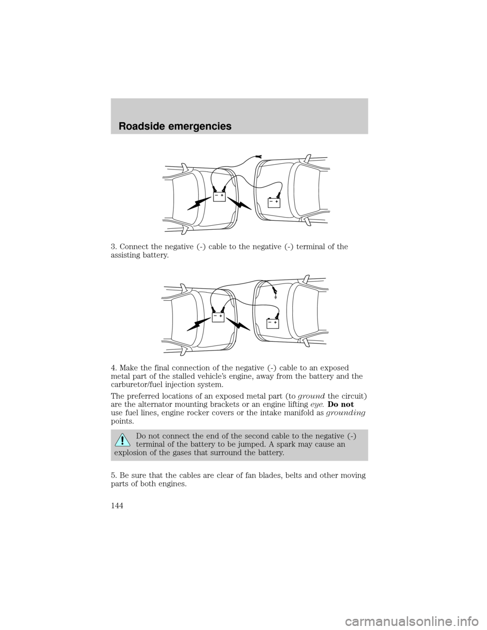
3. Connect the negative (-) cable to the negative (-) terminal of the
assisting battery.
4. Make the final connection of the negative (-) cable to an exposed
metal part of the stalled vehicle's engine, away from the battery and the
carburetor/fuel injection system.
The preferred locations of an exposed metal part (togroundthe circuit)
are the alternator mounting brackets or an engine liftingeye.Do not
use fuel lines, engine rocker covers or the intake manifold asgrounding
points.
Do not connect the end of the second cable to the negative (-)
terminal of the battery to be jumped. A spark may cause an
explosion of the gases that surround the battery.
5. Be sure that the cables are clear of fan blades, belts and other moving
parts of both engines.
+–+–
+–+–
Roadside emergencies
144
Page 148 of 216
SERVICE RECOMMENDATIONS
To help you service your vehicle:
²We highlight do-it-yourself items in the engine compartment for easy
location.
²We provide a Scheduled Maintenance Guide which makes tracking
routine service easy.
If your vehicle requires professional service, your dealership can provide
necessary parts and service. Check your ªWarranty Guideº to find out
which parts and services are covered.
Use only recommended fuels, lubricants, fluids and service parts
conforming to specifications. Motorcraft parts are designed and built to
provide the best performance in your vehicle.
PRECAUTIONS WHEN SERVICING YOUR VEHICLE
Be especially careful when inspecting or servicing your vehicle.
²Do not work on a hot engine.
²When the engine is running, make sure that loose clothing, jewelry or
long hair does not get caught up in moving parts.
²Do not work on a vehicle with the engine running in an enclosed
space, unless you are sure you have enough ventilation.
²Keep all lit cigarettes, open flames and other lit material away from
the battery and all fuel related parts.
If you disconnect the battery, the engine must ªrelearnº its idle
conditions before your vehicle will drive properly, as explained inBattery
in this chapter.
Working with the engine off
1. Set the parking brake and ensure the gearshift is securely latched in P
(Park).
2. Turn off the engine and remove the key.
3. Block the wheels to prevent the vehicle from moving unexpectedly.
Working with the engine on
1. Set the parking brake and ensure the gearshift is securely latched in P
(Park).
2. Block the wheels to prevent the vehicle from moving unexpectedly.
Maintenance and care
148