maintenance FORD EXPEDITION 2000 1.G Owners Manual
[x] Cancel search | Manufacturer: FORD, Model Year: 2000, Model line: EXPEDITION, Model: FORD EXPEDITION 2000 1.GPages: 256, PDF Size: 2.08 MB
Page 1 of 256
Before driving
Introduction 2
Instrumentation 6
Controls and features 19
Seating and safety restraints 92
Starting and driving
Starting 129
Driving 134
Roadside emergencies 159
Servicing
Maintenance and care 181
Capacities and specifications 226
Customer assistance 235
Reporting safety defects 247
Index 248
All rights reserved. Reproduction by any means, electronic or mechanical including
photocopying, recording or by any information storage and retrieval system or translation
in whole or part is not permitted without written authorization from Ford Motor Company.
Ford may change the contents without notice and without incurring obligation.
Copyright 1999 Ford Motor Company
Contents
1
Page 10 of 256
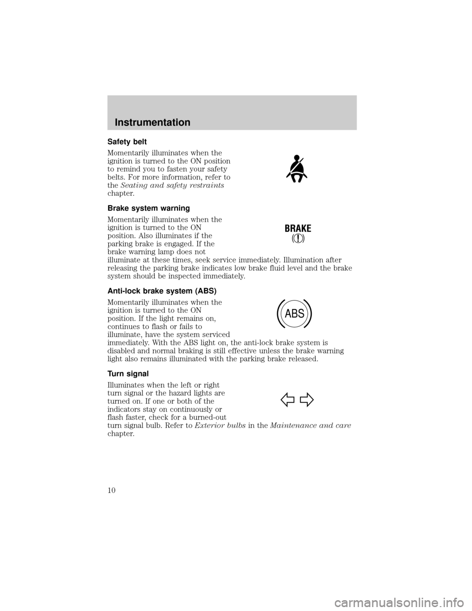
Safety belt
Momentarily illuminates when the
ignition is turned to the ON position
to remind you to fasten your safety
belts. For more information, refer to
theSeating and safety restraints
chapter.
Brake system warning
Momentarily illuminates when the
ignition is turned to the ON
position. Also illuminates if the
parking brake is engaged. If the
brake warning lamp does not
illuminate at these times, seek service immediately. Illumination after
releasing the parking brake indicates low brake fluid level and the brake
system should be inspected immediately.
Anti-lock brake system (ABS)
Momentarily illuminates when the
ignition is turned to the ON
position. If the light remains on,
continues to flash or fails to
illuminate, have the system serviced
immediately. With the ABS light on, the anti-lock brake system is
disabled and normal braking is still effective unless the brake warning
light also remains illuminated with the parking brake released.
Turn signal
Illuminates when the left or right
turn signal or the hazard lights are
turned on. If one or both of the
indicators stay on continuously or
flash faster, check for a burned-out
turn signal bulb. Refer toExterior bulbsin theMaintenance and care
chapter.
!
BRAKE
ABS
Instrumentation
10
Page 15 of 256
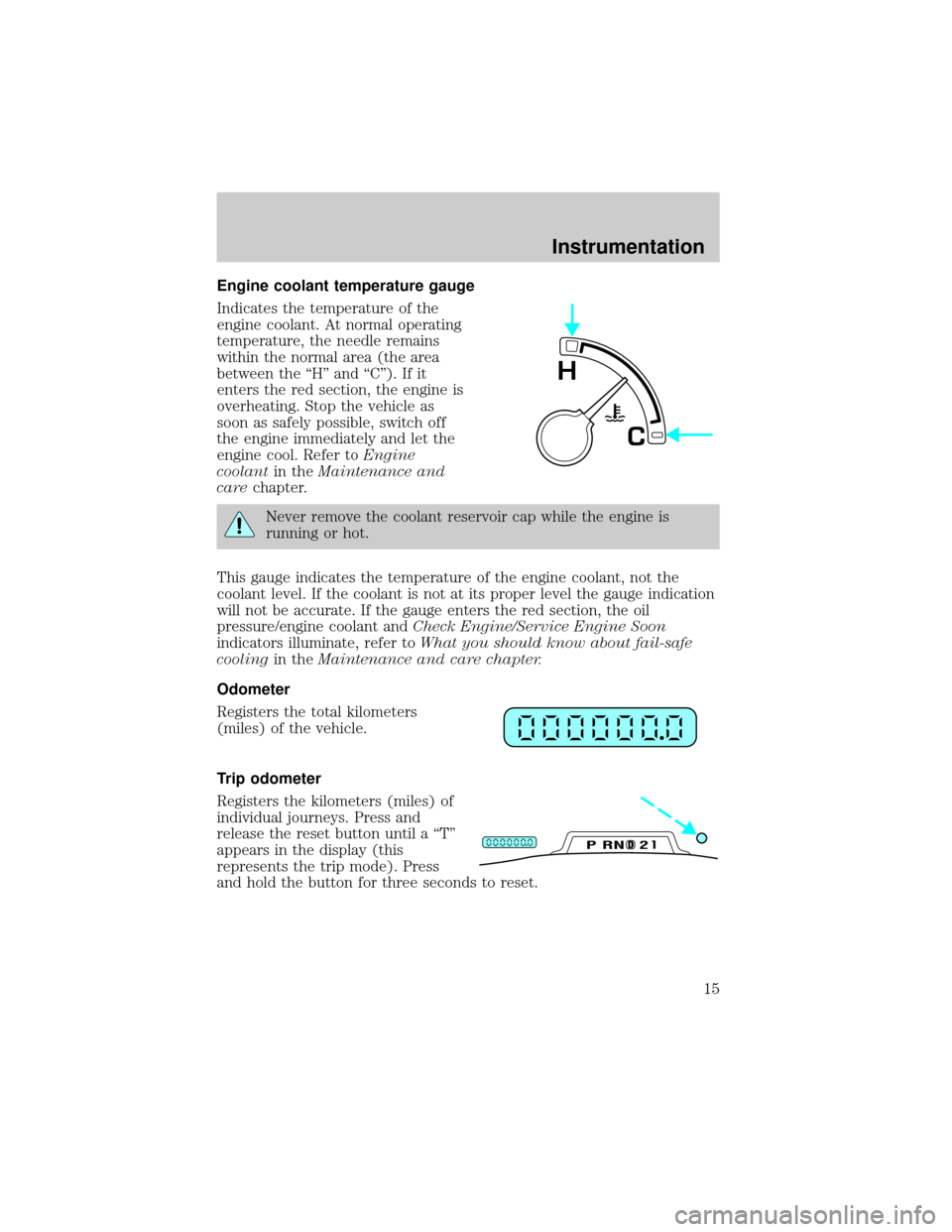
Engine coolant temperature gauge
Indicates the temperature of the
engine coolant. At normal operating
temperature, the needle remains
within the normal area (the area
between the ªHº and ªCº). If it
enters the red section, the engine is
overheating. Stop the vehicle as
soon as safely possible, switch off
the engine immediately and let the
engine cool. Refer toEngine
coolantin theMaintenance and
carechapter.
Never remove the coolant reservoir cap while the engine is
running or hot.
This gauge indicates the temperature of the engine coolant, not the
coolant level. If the coolant is not at its proper level the gauge indication
will not be accurate. If the gauge enters the red section, the oil
pressure/engine coolant andCheck Engine/Service Engine Soon
indicators illuminate, refer toWhat you should know about fail-safe
coolingin theMaintenance and care chapter.
Odometer
Registers the total kilometers
(miles) of the vehicle.
Trip odometer
Registers the kilometers (miles) of
individual journeys. Press and
release the reset button until a ªTº
appears in the display (this
represents the trip mode). Press
and hold the button for three seconds to reset.
C
H
DPRND2
Instrumentation
15
Page 16 of 256
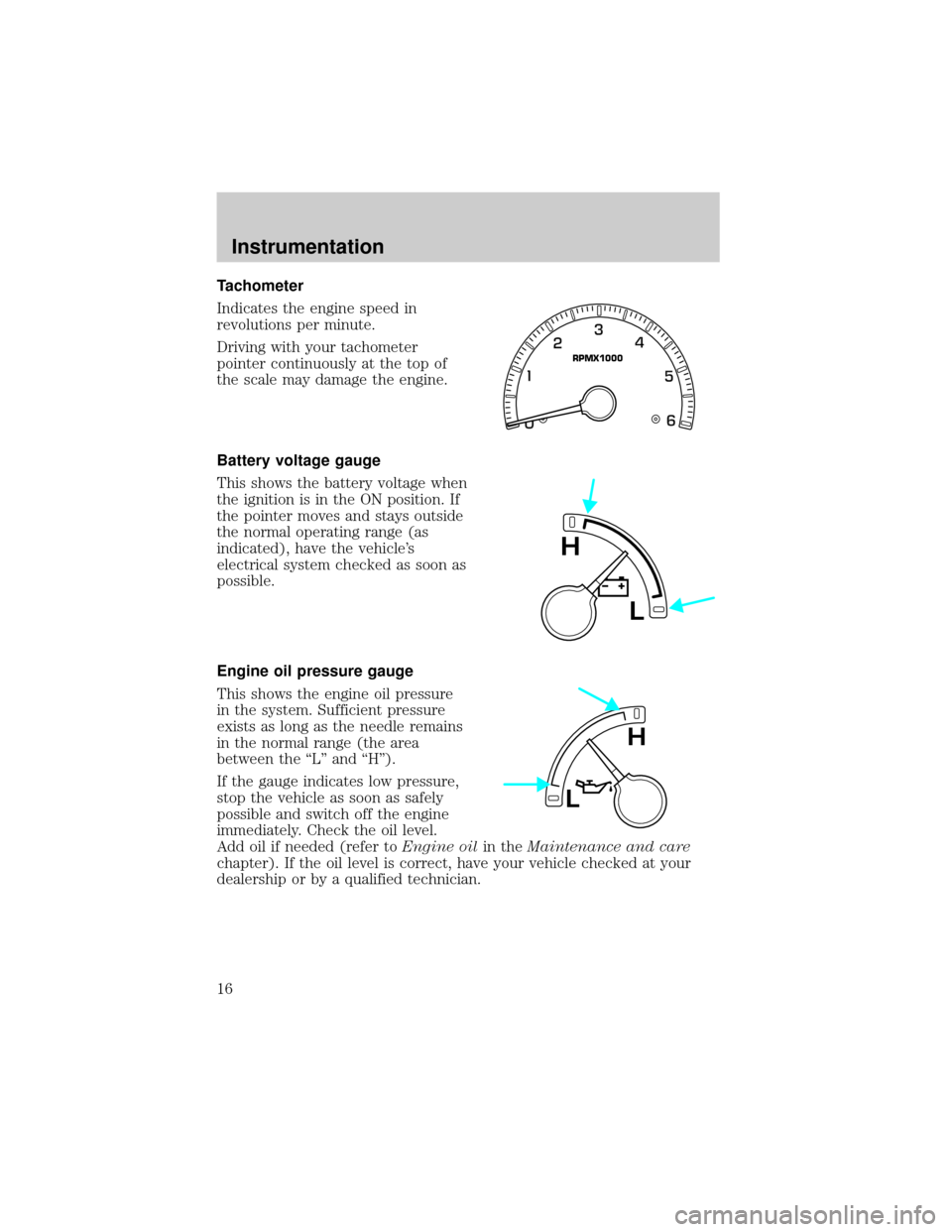
Tachometer
Indicates the engine speed in
revolutions per minute.
Driving with your tachometer
pointer continuously at the top of
the scale may damage the engine.
Battery voltage gauge
This shows the battery voltage when
the ignition is in the ON position. If
the pointer moves and stays outside
the normal operating range (as
indicated), have the vehicle's
electrical system checked as soon as
possible.
Engine oil pressure gauge
This shows the engine oil pressure
in the system. Sufficient pressure
exists as long as the needle remains
in the normal range (the area
between the ªLº and ªHº).
If the gauge indicates low pressure,
stop the vehicle as soon as safely
possible and switch off the engine
immediately. Check the oil level.
Add oil if needed (refer toEngine oilin theMaintenance and care
chapter). If the oil level is correct, have your vehicle checked at your
dealership or by a qualified technician.
RPMX1000
L
H
L
H
Instrumentation
16
Page 113 of 256
6. Within seven seconds of the safety belt warning light turning off,
buckle then unbuckle the safety belt.
²This will disable Belt Minder if it is currently enabled, or enable Belt
Minder if it is currently disabled.
7. Confirmation of disabling Belt Minder is provided by flashing the
safety belt warning light four times per second for three seconds.
8. Confirmation of enabling Belt Minder is provided by flashing the safety
belt warning light four times per second for three seconds, followed by
three seconds with the safety belt warning light off, then followed by
flashing the safety belt warning light four times per second for three
seconds again.
9. After receiving confirmation, the deactivation/activation procedure is
complete.
Safety belt maintenance
Inspect the safety belt systems periodically to make sure they work
properly and are not damaged. Inspect the safety belts to make sure
there are no nicks, wears or cuts, replacing if necessary. All safety belt
assemblies, including retractors, buckles, front seat belt buckle
assemblies, buckle support assemblies (slide bar-if equipped), shoulder
belt height adjusters (if equipped), shoulder belt guide on seatback (if
equipped), child safety seat tether bracket assemblies (if equipped), and
attaching hardware, should be inspected after a collision. Ford
recommends that all safety belt assemblies used in vehicles involved in a
collision be replaced. However, if the collision was minor and a qualified
technician finds that the belts do not show damage and continue to
operate properly, they do not need to be replaced. Safety belt assemblies
not in use during a collision should also be inspected and replaced if
either damage or improper operation is noted.
Failure to inspect and if necessary replace the safety belt
assembly under the above conditions could result in severe
personal injuries in the event of a collision.
Refer toCleaning and maintaining the safety beltsin the
Maintenance and caresection.
Seating and safety restraints
113
Page 118 of 256
The RCM (restraints control module) monitors its own internal circuits
and the supplemental air bag electrical system warning (including the
impact sensors, the system wiring, the air bag system readiness light, the
air bag back up power and the air bag ignitors).
Determining if the system is operational
The SRS uses a readiness light in the instrument cluster or a tone to
indicate the condition of the system. Refer to theAir bag readiness
section in theInstrumentationchapter. Routine maintenance of the air
bag is not required.
A difficulty with the system is indicated by one or more of the following:
²The readiness light will either
flash or stay lit.
²The readiness light will not
illuminate immediately after ignition is turned on.
²A series of five beeps will be heard. The tone pattern will repeat
periodically until the problem and light are repaired.
If any of these things happen, even intermittently, have the SRS serviced
at your dealership or by a qualified technician immediately. Unless
serviced, the system may not function properly in the event of a
collision.
Disposal of air bags and air bag equipped vehicles
(including pretensioners)
For disposal of air bags or air bag equipped vehicles, see your local
dealership or qualified technician. Air bags MUST BE disposed of by
qualified personnel.
SIDE AIR BAG SYSTEM (IF EQUIPPED)
Do not place objects or mount equipment on or near the air bag
cover on the side of the seatbacks of the front seats or in front
seat areas that may come into contact with a deploying air bag. Failure
to follow these instructions may increase the risk of personal injury in
the event of a collision.
Seating and safety restraints
118
Page 120 of 256
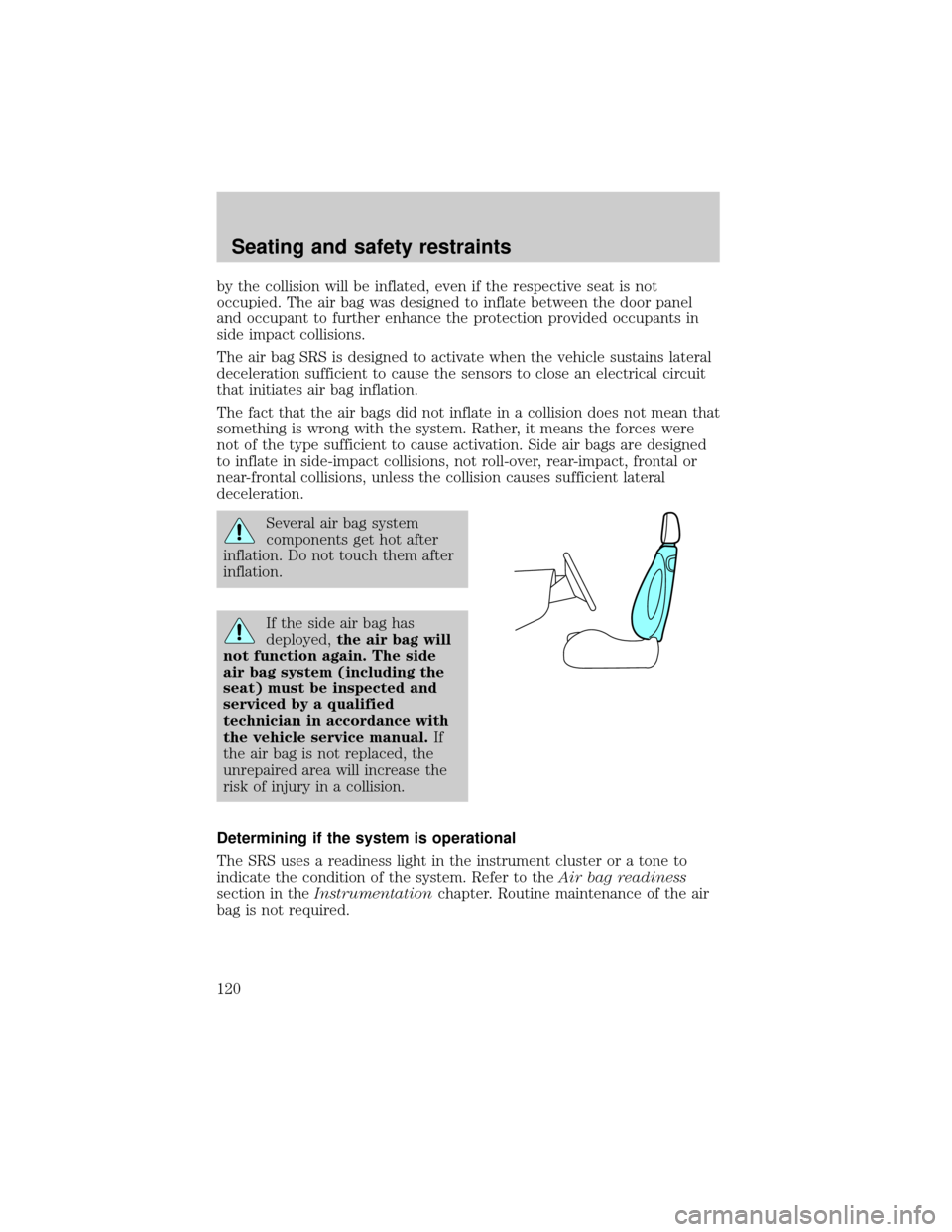
by the collision will be inflated, even if the respective seat is not
occupied. The air bag was designed to inflate between the door panel
and occupant to further enhance the protection provided occupants in
side impact collisions.
The air bag SRS is designed to activate when the vehicle sustains lateral
deceleration sufficient to cause the sensors to close an electrical circuit
that initiates air bag inflation.
The fact that the air bags did not inflate in a collision does not mean that
something is wrong with the system. Rather, it means the forces were
not of the type sufficient to cause activation. Side air bags are designed
to inflate in side-impact collisions, not roll-over, rear-impact, frontal or
near-frontal collisions, unless the collision causes sufficient lateral
deceleration.
Several air bag system
components get hot after
inflation. Do not touch them after
inflation.
If the side air bag has
deployed,the air bag will
not function again. The side
air bag system (including the
seat) must be inspected and
serviced by a qualified
technician in accordance with
the vehicle service manual.If
the air bag is not replaced, the
unrepaired area will increase the
risk of injury in a collision.
Determining if the system is operational
The SRS uses a readiness light in the instrument cluster or a tone to
indicate the condition of the system. Refer to theAir bag readiness
section in theInstrumentationchapter. Routine maintenance of the air
bag is not required.
Seating and safety restraints
120
Page 134 of 256
BRAKES
Your service brakes are self-adjusting. Refer to the scheduled
maintenance guide for scheduled maintenance.
Occasional brake noise is normal and often does not indicate a
performance concern with the vehicle's brake system. In normal
operation, automotive brake systems may emit occasional or intermittent
squeal or groan noises when the brakes are applied. Such noises are
usually heard during the first few brake applications in the morning;
however, they may be heard at any time while braking and can be
aggravated by environmental conditions such as cold, heat, moisture,
road dust, salt or mud. If a ªmetal-to-metal,º ªcontinuous grindingº or
ªcontinuous squealº sound is present while braking, the brake linings
may be worn-out and should be inspected by a qualified service
technician.
Anti-lock brake system (ABS)
On vehicles equipped with an anti-lock braking system (ABS), a noise
from the hydraulic pump motor and pulsation in the pedal may be
observed during ABS braking events. Pedal pulsation coupled with noise
while braking under panic conditions or on loose gravel, bumps, wet or
snowy roads is normal and indicates proper functioning of the vehicle's
anti-lock brake system. The ABS performs a self-check after you start
the engine and begin to drive away. A brief mechanical noise may be
heard during this test. This is normal. If a malfunction is found, the ABS
warning light will come on. If the vehicle has continuous vibration or
shudder in the steering wheel while braking, the vehicle should be
inspected by a qualified service technician.
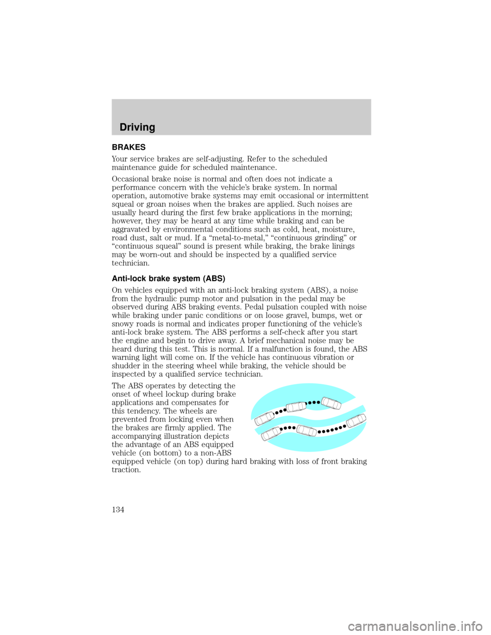
The ABS operates by detecting the
onset of wheel lockup during brake
applications and compensates for
this tendency. The wheels are
prevented from locking even when
the brakes are firmly applied. The
accompanying illustration depicts
the advantage of an ABS equipped
vehicle (on bottom) to a non-ABS
equipped vehicle (on top) during hard braking with loss of front braking
traction.
Driving
134
Page 156 of 256

1 814 kg (4 000 lb.) trailer weight and 181 kg (400 lb.) tongue weight
capability.
Use a frame-mounted weight distributing hitch for trailers over 1814 kg
(4 000 lb).
Driving while you tow
When towing a trailer:
²Ensure that you turn off your speed control. The speed control may
shut off automatically when you are towing on long, steep grades.
²Consult your local motor vehicle speed regulations for towing a trailer.
²Use a lower gear when towing up or down steep hills. This will
eliminate excessive downshifting and upshifting for optimum fuel
economy and transmission cooling.
²Anticipate stops and brake gradually.
Exceeding the GCWR rating may cause internal transmission
damage and void your warranty coverage.
Servicing after towing
If you tow a trailer for long distances, your vehicle will require more
frequent service intervals. Refer to your Scheduled Maintenance guide
for more information.
Recreational towing (all wheels on the ground)
An example of recreational towing would be towing your vehicle behind
a Motorhome. Follow these guidelines if you have the need for
recreational towing your vehicle with all four wheels on the ground.
These guidelines are designed to ensure that your transmission is not
damaged.
2WD vehicles (with automatic transmissions)
²Place the transmission in N (Neutral)
²Maximum speed is 56 km (35 mph)
²Maximum distance is 80 km (50 miles)
If a distance of 80 km (50 miles) or a speed of 56 km (35 mph) must be
exceeded, the drive shaft will have to be removed until the vehicle is
being towed.
Ford recommends the driveshaft be removed/installed only by a qualified
technician. See your local dealer for driveshaft removal/installation.
Driving
156
Page 166 of 256
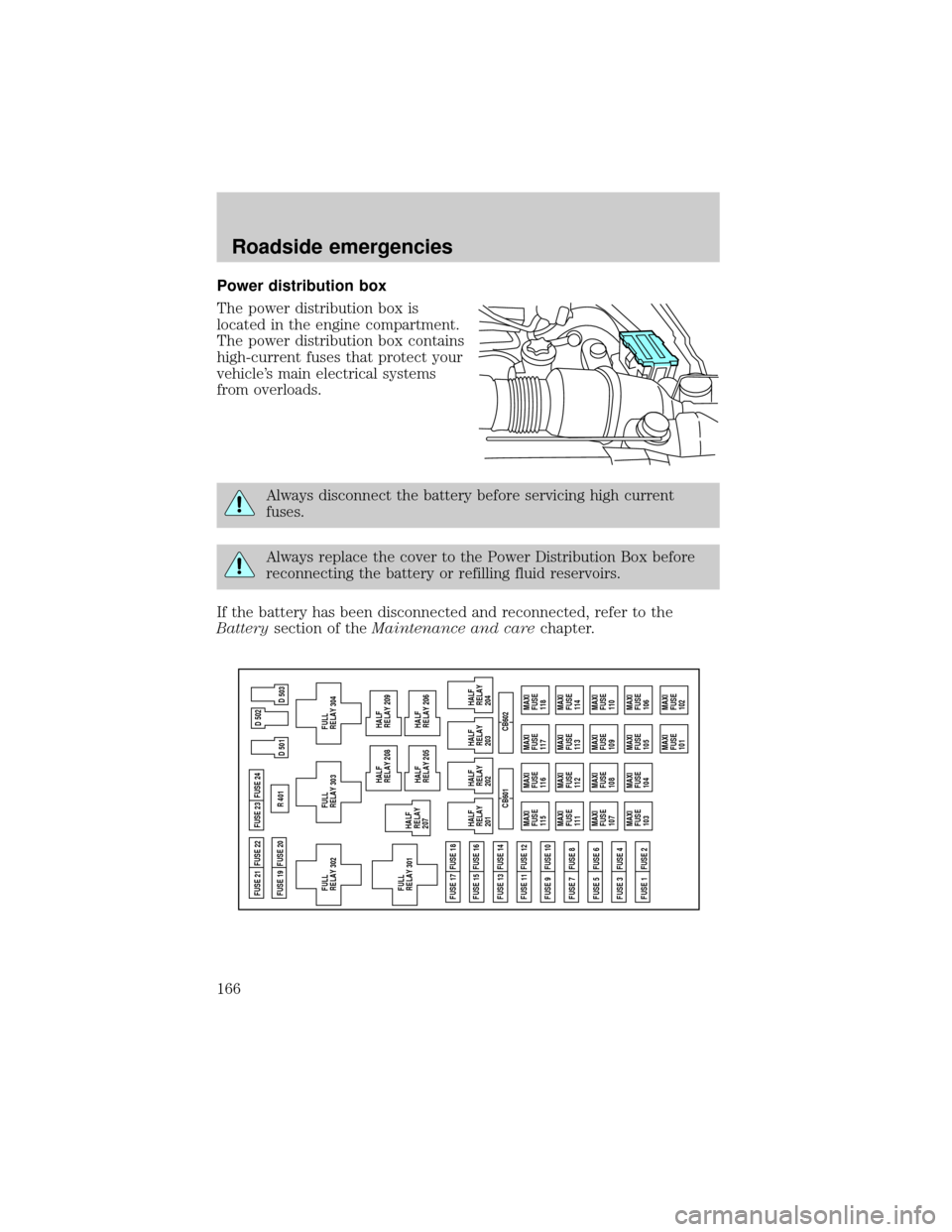
Power distribution box
The power distribution box is
located in the engine compartment.
The power distribution box contains
high-current fuses that protect your
vehicle's main electrical systems
from overloads.
Always disconnect the battery before servicing high current
fuses.
Always replace the cover to the Power Distribution Box before
reconnecting the battery or refilling fluid reservoirs.
If the battery has been disconnected and reconnected, refer to the
Batterysection of theMaintenance and carechapter.
MAXI
FUSE
115MAXI
FUSE
116MAXI
FUSE
117
MAXI
FUSE
118
MAXI
FUSE
111MAXI
FUSE
112MAXI
FUSE
113
MAXI
FUSE
114
MAXI
FUSE
107MAXI
FUSE
108MAXI
FUSE
109
MAXI
FUSE
110
MAXI
FUSE
103MAXI
FUSE
104MAXI
FUSE
105
MAXI
FUSE
106
MAXI
FUSE
101MAXI
FUSE
102 CB601 CB602 FUSE 17 FUSE 18FUSE 21 FUSE 22
FUSE 19 FUSE 20FUSE 23
FULL
RELAY 302R 401
D 501 FUSE 24
FUSE 15 FUSE 16
FUSE 13 FUSE 14
FUSE 11 FUSE 12
FUSE 9 FUSE 10
FUSE 7 FUSE 8
FUSE 5 FUSE 6
FUSE 3 FUSE 4
FUSE 1 FUSE 2
D 503 D 502
FULL
RELAY 301HALF
RELAY
207
FULL
RELAY 303
FULL
RELAY 304
HALF
RELAY
201
HALF
RELAY
202HALF
RELAY 208
HALF
RELAY 209
HALF
RELAY 205
HALF
RELAY 206
HALF
RELAY
203
HALF
RELAY
204
Roadside emergencies
166