wiring FORD EXPEDITION 2000 1.G Owners Manual
[x] Cancel search | Manufacturer: FORD, Model Year: 2000, Model line: EXPEDITION, Model: FORD EXPEDITION 2000 1.GPages: 256, PDF Size: 2.08 MB
Page 117 of 256
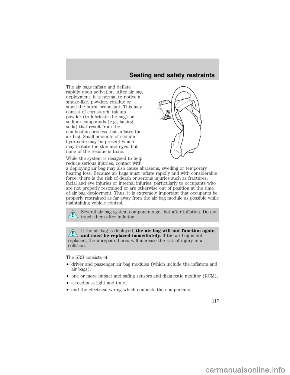
The air bags inflate and deflate
rapidly upon activation. After air bag
deployment, it is normal to notice a
smoke-like, powdery residue or
smell the burnt propellant. This may
consist of cornstarch, talcum
powder (to lubricate the bag) or
sodium compounds (e.g., baking
soda) that result from the
combustion process that inflates the
air bag. Small amounts of sodium
hydroxide may be present which
may irritate the skin and eyes, but
none of the residue is toxic.
While the system is designed to help
reduce serious injuries, contact with
a deploying air bag may also cause abrasions, swelling or temporary
hearing loss. Because air bags must inflate rapidly and with considerable
force, there is the risk of death or serious injuries such as fractures,
facial and eye injuries or internal injuries, particularly to occupants who
are not properly restrained or are otherwise out of position at the time
of air bag deployment. Thus, it is extremely important that occupants be
properly restrained as far away from the air bag module as possible while
maintaining vehicle control.
Several air bag system components get hot after inflation. Do not
touch them after inflation.
If the air bag is deployed,the air bag will not function again
and must be replaced immediately.If the air bag is not
replaced, the unrepaired area will increase the risk of injury in a
collision.
The SRS consists of:
²driver and passenger air bag modules (which include the inflators and
air bags),
²one or more impact and safing sensors and diagnostic monitor (RCM),
²a readiness light and tone,
²and the electrical wiring which connects the components.
Seating and safety restraints
117
Page 118 of 256
The RCM (restraints control module) monitors its own internal circuits
and the supplemental air bag electrical system warning (including the
impact sensors, the system wiring, the air bag system readiness light, the
air bag back up power and the air bag ignitors).
Determining if the system is operational
The SRS uses a readiness light in the instrument cluster or a tone to
indicate the condition of the system. Refer to theAir bag readiness
section in theInstrumentationchapter. Routine maintenance of the air
bag is not required.
A difficulty with the system is indicated by one or more of the following:
²The readiness light will either
flash or stay lit.
²The readiness light will not
illuminate immediately after ignition is turned on.
²A series of five beeps will be heard. The tone pattern will repeat
periodically until the problem and light are repaired.
If any of these things happen, even intermittently, have the SRS serviced
at your dealership or by a qualified technician immediately. Unless
serviced, the system may not function properly in the event of a
collision.
Disposal of air bags and air bag equipped vehicles
(including pretensioners)
For disposal of air bags or air bag equipped vehicles, see your local
dealership or qualified technician. Air bags MUST BE disposed of by
qualified personnel.
SIDE AIR BAG SYSTEM (IF EQUIPPED)
Do not place objects or mount equipment on or near the air bag
cover on the side of the seatbacks of the front seats or in front
seat areas that may come into contact with a deploying air bag. Failure
to follow these instructions may increase the risk of personal injury in
the event of a collision.
Seating and safety restraints
118
Page 152 of 256
2. Weigh your vehicle as you customarily operate the vehicle without
cargo. To obtain correct weights, try taking your vehicle to a shipping
company or an inspection station for trucks.
3. Subtract your loaded vehicle weight from the maximum GCWR on the
following charts. This is the maximum trailer weight your vehicle can tow
and must fall below the maximum shown under maximum trailer weight
on the chart.
TRAILER TOWING
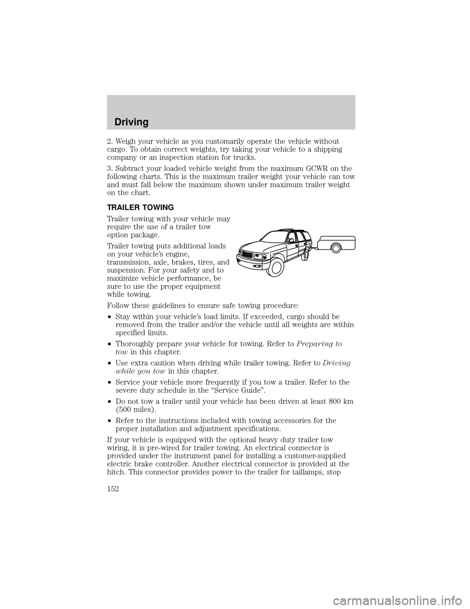
Trailer towing with your vehicle may
require the use of a trailer tow
option package.
Trailer towing puts additional loads
on your vehicle's engine,
transmission, axle, brakes, tires, and
suspension. For your safety and to
maximize vehicle performance, be
sure to use the proper equipment
while towing.
Follow these guidelines to ensure safe towing procedure:
²Stay within your vehicle's load limits. If exceeded, cargo should be
removed from the trailer and/or the vehicle until all weights are within
specified limits.
²Thoroughly prepare your vehicle for towing. Refer toPreparing to
towin this chapter.
²Use extra caution when driving while trailer towing. Refer toDriving
while you towin this chapter.
²Service your vehicle more frequently if you tow a trailer. Refer to the
severe duty schedule in the ªService Guideº.
²Do not tow a trailer until your vehicle has been driven at least 800 km
(500 miles).
²Refer to the instructions included with towing accessories for the
proper installation and adjustment specifications.
If your vehicle is equipped with the optional heavy duty trailer tow
wiring, it is pre-wired for trailer towing. An electrical connector is
provided under the instrument panel for installing a customer-supplied
electric brake controller. Another electrical connector is provided at the
hitch. This connector provides power to the trailer for taillamps, stop
Driving
152
Page 158 of 256
Disconnect the wiring to the trailer before backing the trailer into the
water. Reconnect the wiring to the trailer after the trailer is removed
from the water.
LUGGAGE RACK (IF EQUIPPED)
The rear crossbar can be adjusted to fit the item being carried. The front
crossbar does not move.
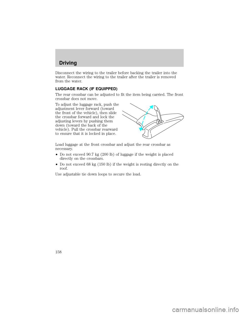
To adjust the luggage rack, push the
adjustment lever forward (toward
the front of the vehicle), then slide
the crossbar forward and lock the
adjusting levers by pushing them
down (toward the back of the
vehicle). Pull the crossbar rearward
to ensure that it is locked in place.
Load luggage at the front crossbar and adjust the rear crossbar as
necessary.
²Do not exceed 90.7 kg (200 lb) of luggage if the weight is placed
directly on the crossbars.
²Do not exceed 68 kg (150 lb) if the weight is resting directly on the
roof.
Use adjustable tie down loops to secure the load.
Driving
158
Page 205 of 256
Do not replace your tires with ªhigh performanceº tires or larger
size tires.
Failure to follow these precautions may adversely affect the
handling of the vehicle and make it easier for the driver to lose
control and roll over.
Tires that are larger or smaller than your vehicle's original tires may also
affect the accuracy of your speedometer.
SNOW TIRES AND CHAINS
Snow tires must be the same size and grade as the tires you
currently have on your vehicle.
The tires on your vehicle have all weather treads to provide traction in
rain and snow. However, in some climates, you may need to use snow
tires and chains.
Follow these guidelines when using snow tires and chains:
²Use only cable type chains offered by Ford as an accessory or
equivalent. SAE class ªSº or other conventional link type chains may
contact and cause damage to the vehicle's wheel house and/or body.
²Install chains securely, verifying that the chains do not touch any
wiring, brake lines or fuel lines.
²Drive cautiously. If you hear the chains rub or bang against your
vehicle, stop and re-tighten the chains. If this does not work, remove
the chains to prevent damage to your vehicle.
²If possible, avoid fully loading your vehicle.
²Remove the tire chains when they are no longer needed. Do not use
tire chains on dry roads.
²The suspension insulation and bumpers will help prevent vehicle
damage. Do not remove these components from your vehicle when
using snow tires and chains.
²Do not exceed 48 km/h (30 mph) with tire chains on your vehicle.
Maintenance and care
205
Page 216 of 256
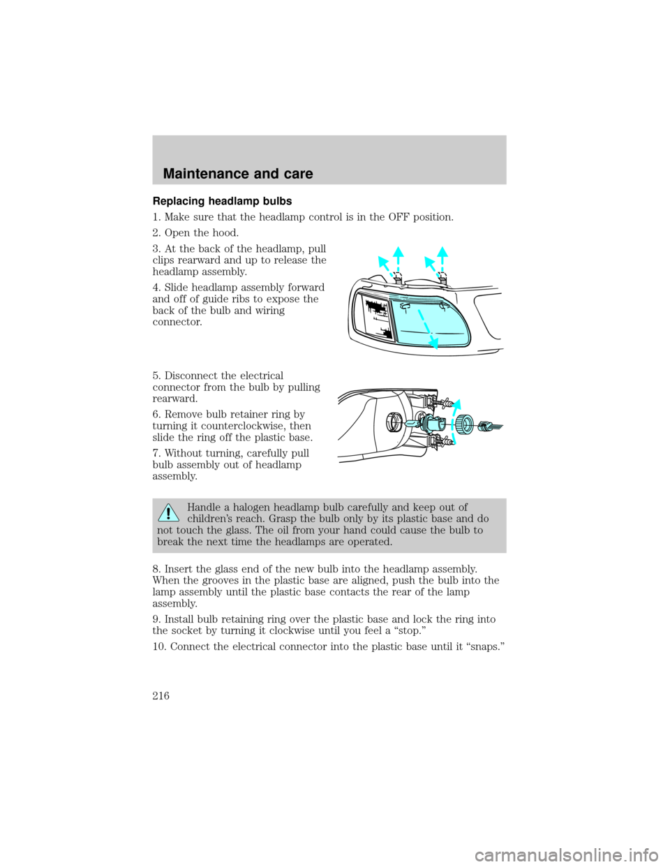
Replacing headlamp bulbs
1. Make sure that the headlamp control is in the OFF position.
2. Open the hood.
3. At the back of the headlamp, pull
clips rearward and up to release the
headlamp assembly.
4. Slide headlamp assembly forward
and off of guide ribs to expose the
back of the bulb and wiring
connector.
5. Disconnect the electrical
connector from the bulb by pulling
rearward.
6. Remove bulb retainer ring by
turning it counterclockwise, then
slide the ring off the plastic base.
7. Without turning, carefully pull
bulb assembly out of headlamp
assembly.
Handle a halogen headlamp bulb carefully and keep out of
children's reach. Grasp the bulb only by its plastic base and do
not touch the glass. The oil from your hand could cause the bulb to
break the next time the headlamps are operated.
8. Insert the glass end of the new bulb into the headlamp assembly.
When the grooves in the plastic base are aligned, push the bulb into the
lamp assembly until the plastic base contacts the rear of the lamp
assembly.
9. Install bulb retaining ring over the plastic base and lock the ring into
the socket by turning it clockwise until you feel a ªstop.º
10. Connect the electrical connector into the plastic base until it ªsnaps.º
Maintenance and care
216
Page 244 of 256

Comfort and convenience
Cabin air filter
Cargo nets
Cargo organizers
Cargo trays
Dash trim (wood grain)
Engine block heaters
Tire step
Travel equipment
Auto headlamps with DRL
Bumper mount bike carrier
Daytime running lights (DRL)
Factory luggage rack adaptors
Fog lights
Framed luggage covers
Heavy-duty battery
Luggage/cargo basket
Removable luggage rack (Track rider bars)
Removable luggage rack adapters
Running boards (Molded and tubular)
Snow traction cables
Soft luggage cover
Towing mirrors (Removable and permanent)
Trailer hitch (Class III)
Trailer hitch bars and balls
Trailer hitch wiring adaptor
Protection and appearance equipment
Air bag anti-theft locks
Car/truck covers
Cargo liners, interior
Customer assistance
244