trip computer FORD EXPEDITION 2001 1.G Owners Manual
[x] Cancel search | Manufacturer: FORD, Model Year: 2001, Model line: EXPEDITION, Model: FORD EXPEDITION 2001 1.GPages: 280, PDF Size: 1.79 MB
Page 19 of 280
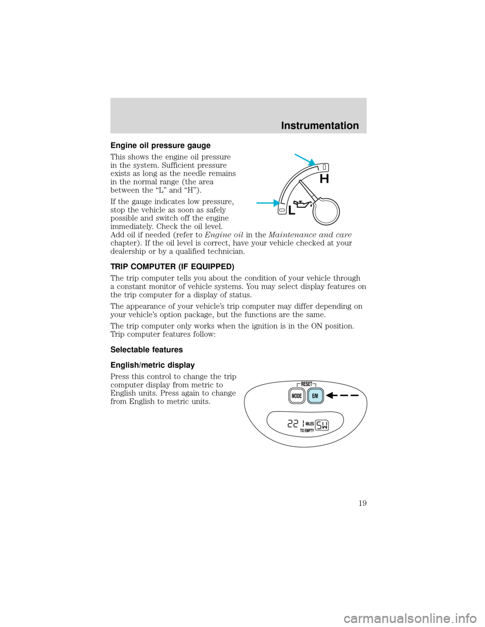
Engine oil pressure gauge
This shows the engine oil pressure
in the system. Sufficient pressure
exists as long as the needle remains
in the normal range (the area
between the“L”and“H”).
If the gauge indicates low pressure,
stop the vehicle as soon as safely
possible and switch off the engine
immediately. Check the oil level.
Add oil if needed (refer toEngine oilin theMaintenance and care
chapter). If the oil level is correct, have your vehicle checked at your
dealership or by a qualified technician.
TRIP COMPUTER (IF EQUIPPED)
The trip computer tells you about the condition of your vehicle through
a constant monitor of vehicle systems. You may select display features on
the trip computer for a display of status.
The appearance of your vehicle’s trip computer may differ depending on
your vehicle’s option package, but the functions are the same.
The trip computer only works when the ignition is in the ON position.
Trip computer features follow:
Selectable features
English/metric display
Press this control to change the trip
computer display from metric to
English units. Press again to change
from English to metric units.
L
H
Instrumentation
19
Page 61 of 280
windshield. In approximately 31⁄2minutes or less, the fan speed will start
to increase and the airflow location will change to the floor area.
If unusual conditions exist (i.e.-window fogging, etc.), the manual
override controls allow you to select airflow locations and the fan control
allows you to adjust fan speed as necessary.
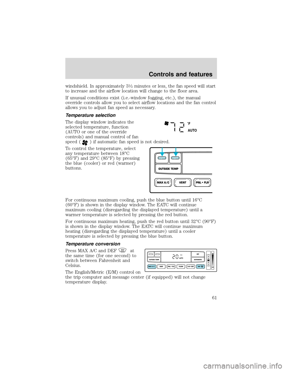
Temperature selection
The display window indicates the
selected temperature, function
(AUTO or one of the override
controls) and manual control of fan
speed (
) if automatic fan speed is not desired.
To control the temperature, select
any temperature between 18°C
(65°F) and 29°C (85°F) by pressing
the blue (cooler) or red (warmer)
buttons.
For continuous maximum cooling, push the blue button until 16°C
(60°F) is shown in the display window. The EATC will continue
maximum cooling (disregarding the displayed temperature) until a
warmer temperature is selected by pressing the red button.
For continuous maximum heating, push the red button until 32°C (90°F)
is shown in the display window. The EATC will continue maximum
heating (disregarding the displayed temperature) until a cooler
temperature is selected by pressing the blue button.
Temperature conversion
Press MAX A/C and DEF
at
the same time (for one second) to
switch between Fahrenheit and
Celsius.
The English/Metric (E/M) control on
the trip computer and message center (if equipped) will not change
temperature display.
˚F
AUTO
VENTPNL • FLRMAX A/C
OUTSIDE TEMP
VENT PNL • FLR FLOOR FLR • DEF DEF
HI
LO
MAX A/C
OUTSIDE TEMP AUTOMATICOFFAUTO
Controls and features
61
Page 77 of 280
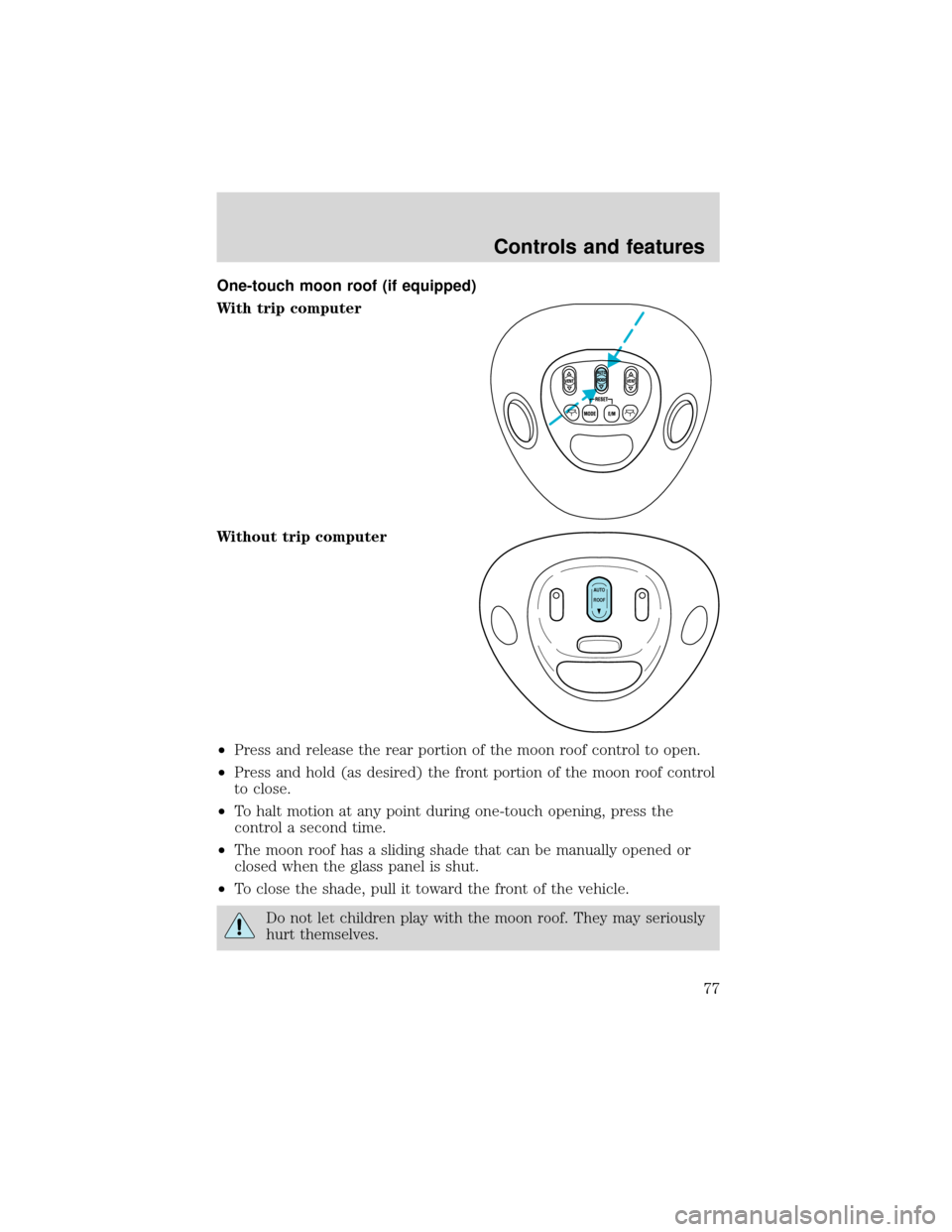
One-touch moon roof (if equipped)
With trip computer
Without trip computer
•Press and release the rear portion of the moon roof control to open.
•Press and hold (as desired) the front portion of the moon roof control
to close.
•To halt motion at any point during one-touch opening, press the
control a second time.
•The moon roof has a sliding shade that can be manually opened or
closed when the glass panel is shut.
•To close the shade, pull it toward the front of the vehicle.
Do not let children play with the moon roof. They may seriously
hurt themselves.
VENT VENTROOF
AUTO
ROOF
Controls and features
77
Page 78 of 280
Trip computer
For information on the trip computer, refer toTrip computerin the
Instrumentationchapter.
Electronic compass (if equipped)
The compass reading may be affected when you drive near large
buildings, bridges, power lines and powerful broadcast antennas.
Magnetic or metallic objects placed in, on or near the vehicle may also
affect compass accuracy.
Usually, when something affects the compass readings, the compass will
correct itself after a few days of operating your vehicle in normal
conditions. If the compass still appears to be inaccurate, a manual
calibration may be necessary. Refer toCompass calibration
adjustment.
Most geographic areas (zones) have a magnetic north compass point that
varies slightly from the northerly direction on maps. This variation is four
degrees between adjacent zones and will become noticeable as the
vehicle crosses multiple zones. A correct zone setting will eliminate this
error. Refer toCompass zone adjustment.
Electronic compass/temperature display (without trip computer)
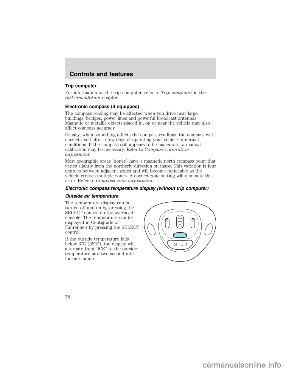
Outside air temperature
The temperature display can be
turned off and on by pressing the
SELECT control on the overhead
console. The temperature can be
displayed in Centigrade or
Fahrenheit by pressing the SELECT
control.
If the outside temperature falls
below 3°C (38°F), the display will
alternate from“ICE”to the outside
temperature at a two second rate
for one minute.
AUTO
CAL
ROOF
Controls and features
78
Page 79 of 280
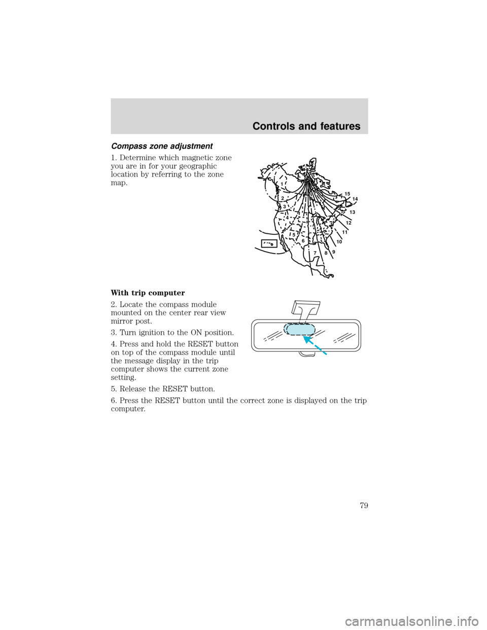
Compass zone adjustment
1. Determine which magnetic zone
you are in for your geographic
location by referring to the zone
map.
With trip computer
2. Locate the compass module
mounted on the center rear view
mirror post.
3. Turn ignition to the ON position.
4. Press and hold the RESET button
on top of the compass module until
the message display in the trip
computer shows the current zone
setting.
5. Release the RESET button.
6. Press the RESET button until the correct zone is displayed on the trip
computer.
1
2
3
4
5
6
7891011121314 15
Controls and features
79
Page 80 of 280
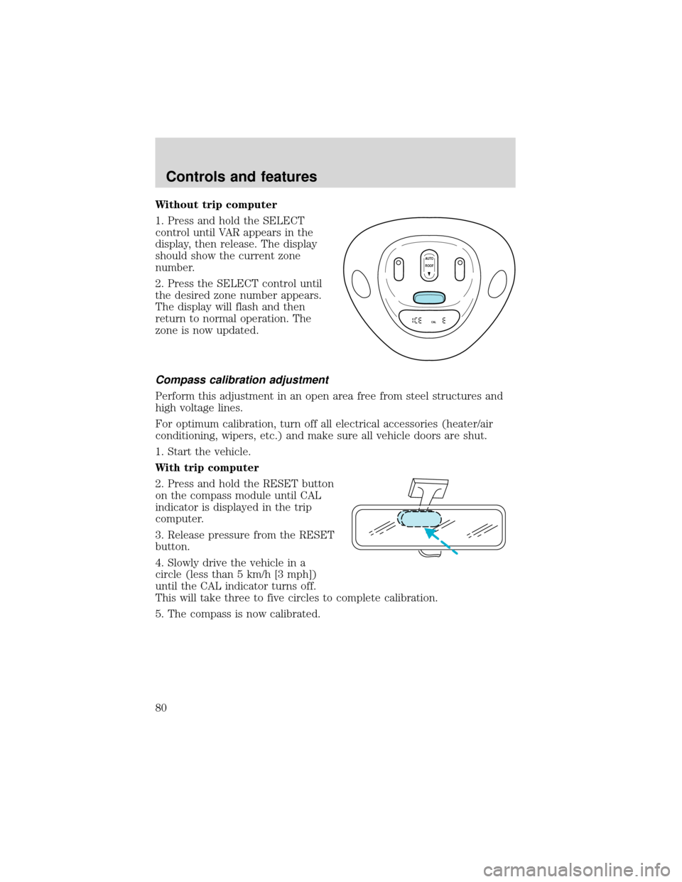
Without trip computer
1. Press and hold the SELECT
control until VAR appears in the
display, then release. The display
should show the current zone
number.
2. Press the SELECT control until
the desired zone number appears.
The display will flash and then
return to normal operation. The
zone is now updated.
Compass calibration adjustment
Perform this adjustment in an open area free from steel structures and
high voltage lines.
For optimum calibration, turn off all electrical accessories (heater/air
conditioning, wipers, etc.) and make sure all vehicle doors are shut.
1. Start the vehicle.
With trip computer
2. Press and hold the RESET button
on the compass module until CAL
indicator is displayed in the trip
computer.
3. Release pressure from the RESET
button.
4. Slowly drive the vehicle in a
circle (less than 5 km/h [3 mph])
until the CAL indicator turns off.
This will take three to five circles to complete calibration.
5. The compass is now calibrated.
AUTO
CAL
ROOF
Controls and features
80
Page 81 of 280
![FORD EXPEDITION 2001 1.G Owners Manual Without trip computer
1. Press and hold the SELECT
control until CAL appears in the
display (approximately eight
seconds) and release.
2. Drive the vehicle slowly (less
than 5 km/h [3 mph]) in circles FORD EXPEDITION 2001 1.G Owners Manual Without trip computer
1. Press and hold the SELECT
control until CAL appears in the
display (approximately eight
seconds) and release.
2. Drive the vehicle slowly (less
than 5 km/h [3 mph]) in circles](/img/11/4910/w960_4910-80.png)
Without trip computer
1. Press and hold the SELECT
control until CAL appears in the
display (approximately eight
seconds) and release.
2. Drive the vehicle slowly (less
than 5 km/h [3 mph]) in circles until
CAL indicator turns off in about 2–3
complete circles.
3. The compass is now calibrated.
Power quarter rear windows (if equipped)
•With out a moon roof
•With a moon roof
AUTO
CAL
ROOF
RESET
VENTV
E
N
T
MODE E/M
VENT VENTROOF
Controls and features
81
Page 82 of 280
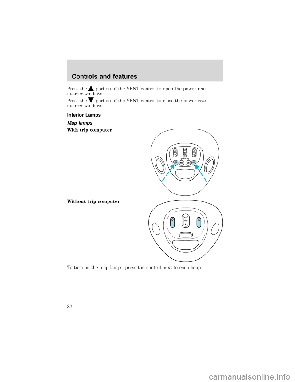
Press theportion of the VENT control to open the power rear
quarter windows.
Press the
portion of the VENT control to close the power rear
quarter windows.
Interior Lamps
Map lamps
With trip computer
Without trip computer
To turn on the map lamps, press the control next to each lamp.
VENT VENTROOF
AUTO
ROOF
Controls and features
82
Page 182 of 280
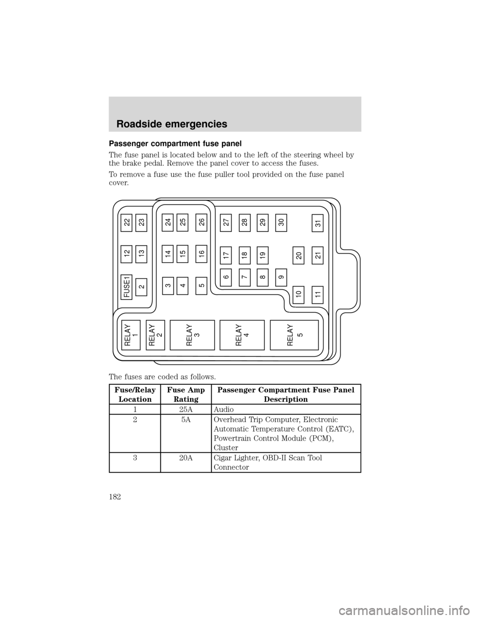
Passenger compartment fuse panel
The fuse panel is located below and to the left of the steering wheel by
the brake pedal. Remove the panel cover to access the fuses.
To remove a fuse use the fuse puller tool provided on the fuse panel
cover.
The fuses are coded as follows.
Fuse/Relay
LocationFuse Amp
RatingPassenger Compartment Fuse Panel
Description
1 25A Audio
2 5A Overhead Trip Computer, Electronic
Automatic Temperature Control (EATC),
Powertrain Control Module (PCM),
Cluster
3 20A Cigar Lighter, OBD-II Scan Tool
Connector
FUSE1 12 22
21323
617 27
718 28
819 29
930
20
31 21 11 10
RELAY
5 RELAY
4 RELAY
3 RELAY
2 RELAY
1
31424
41525
51626
Roadside emergencies
182
Page 183 of 280
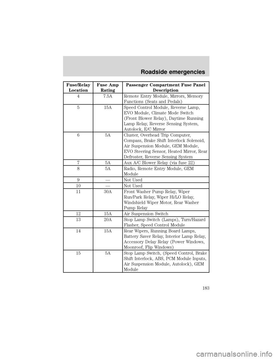
Fuse/Relay
LocationFuse Amp
RatingPassenger Compartment Fuse Panel
Description
4 7.5A Remote Entry Module, Mirrors, Memory
Functions (Seats and Pedals)
5 15A Speed Control Module, Reverse Lamp,
EVO Module, Climate Mode Switch
(Front Blower Relay), Daytime Running
Lamp Relay, Reverse Sensing System,
Autolock, E/C Mirror
6 5A Cluster, Overhead Trip Computer,
Compass, Brake Shift Interlock Solenoid,
Air Suspension Module, GEM Module,
EVO Steering Sensor, Heated Mirror, Rear
Defroster, Reverse Sensing System
7 5A Aux A/C Blower Relay (via fuse 22)
8 5A Radio, Remote Entry Module, GEM
Module
9—Not Used
10—Not Used
11 30A Front Washer Pump Relay, Wiper
Run/Park Relay, Wiper Hi/LO Relay,
Windshield Wiper Motor, Rear Washer
Pump Relay
12 15A Air Suspension Switch
13 20A Stop Lamp Switch (Lamps), Turn/Hazard
Flasher, Speed Control Module
14 15A Rear Wipers, Running Board Lamps,
Battery Saver Relay, Interior Lamp Relay,
Accessory Delay Relay (Power Windows,
Moonroof, Flip Windows)
15 5A Stop Lamp Switch, (Speed Control, Brake
Shift Interlock, ABS, PCM Module Inputs,
Air Suspension Module, Autolock), GEM
Module
Roadside emergencies
183