AUX FORD EXPEDITION 2002 1.G Owners Manual
[x] Cancel search | Manufacturer: FORD, Model Year: 2002, Model line: EXPEDITION, Model: FORD EXPEDITION 2002 1.GPages: 280, PDF Size: 2.32 MB
Page 55 of 280
²Under snowy or dirty weather conditions, your vehicle's climate
control system should be left in the OFF position when the vehicle is
parked. This allows the climate control system to be free from
contamination of outside pollutants.
²If your vehicle has been parked with the windows closed during warm
weather conditions, the air conditioner will perform more efficiently in
cooling the vehicle if driven for two or three minutes with the
windows open. This will force most of the hot, stale air out of the
vehicle. Once the vehicle has been ªaired outº, operate the climate
control system as desired.
²Don't put objects under the front seat that will interfere with the
airflow to the rear seats.
²Remove any snow, ice or leaves from the air intake area at the base of
the windshield.
²Do not place objects over the defroster outlets. These objects can
block airflow and reduce your ability to see through your windshield.
Avoid placing small objects on top of the instrument panel. These
objects may fall down into the defroster outlets and block airflow, in
addition to damaging the climate control system.
To aid in side window defogging/demisting in cold weather conditions:
1. Select PNL²FLR
2. Set the temperature control to full heat
3. Set the fan speed control to HI
4. Direct the outer panel vents towards the side windows.
To increase airflow to the outer panel vents, close the central panel
vents.
Do not place objects on top of the instrument panel, as these
objects may become projectiles in a collision or sudden stop.
AUXILIARY A/C-HEATER CONTROLS (IF EQUIPPED)
Depending on your equipment package, your vehicle may be equipped
with auxiliary A/C-heater controls. The auxiliary A/C-heater feature
provides increased capacity to quickly heat or cool the vehicle. Besides
the driver's control panel for the front seat occupants, the second row
auxiliary A/C-heater controls allow the rear passengers to control the
Climate controls
55
Page 56 of 280
temperature in the rear of the vehicle through a second control panel
above the second row, or in the floor console.
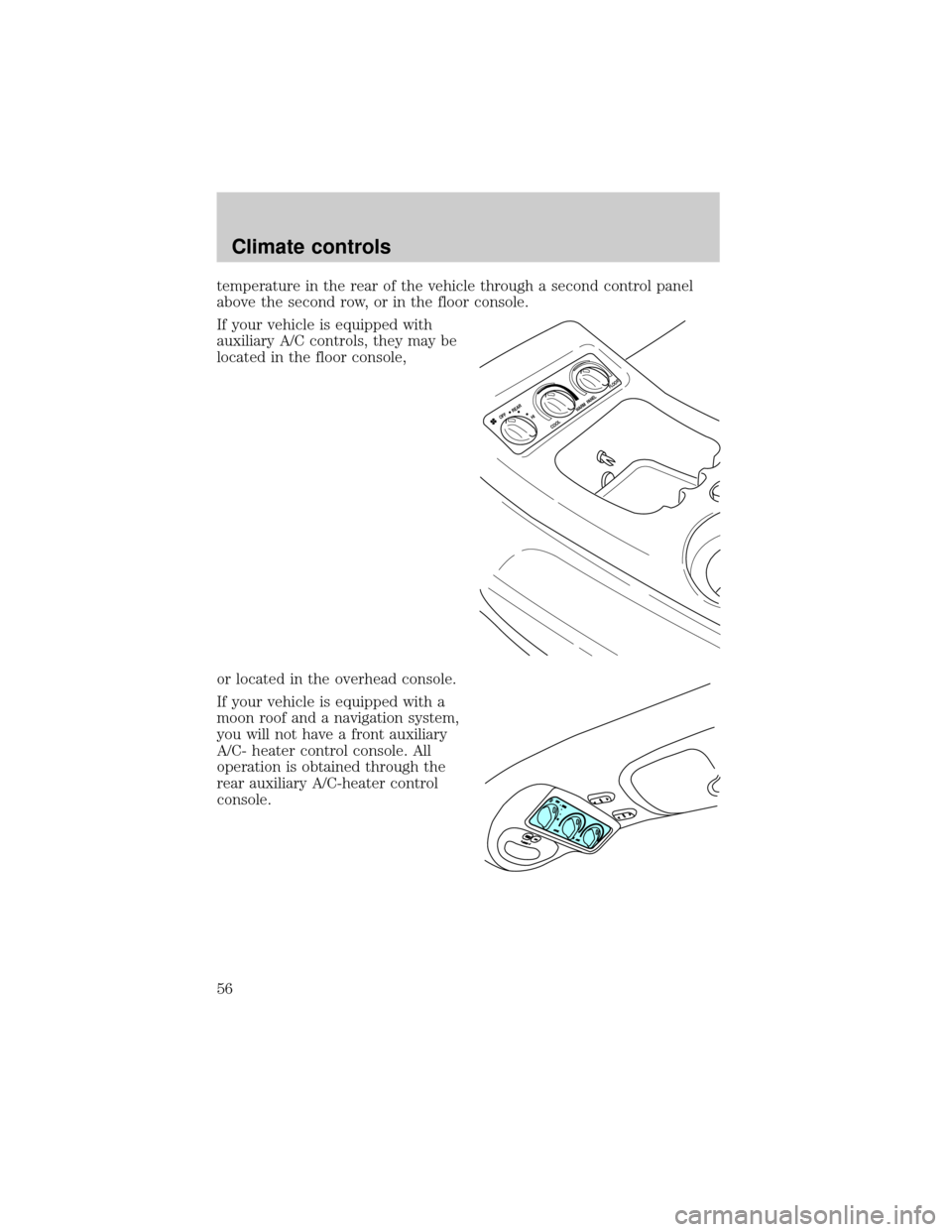
If your vehicle is equipped with
auxiliary A/C controls, they may be
located in the floor console,
or located in the overhead console.
If your vehicle is equipped with a
moon roof and a navigation system,
you will not have a front auxiliary
A/C- heater control console. All
operation is obtained through the
rear auxiliary A/C-heater control
console.
HI OFF
REARWARM
COOL
PANEL
FLOOR
Climate controls
56
Page 57 of 280
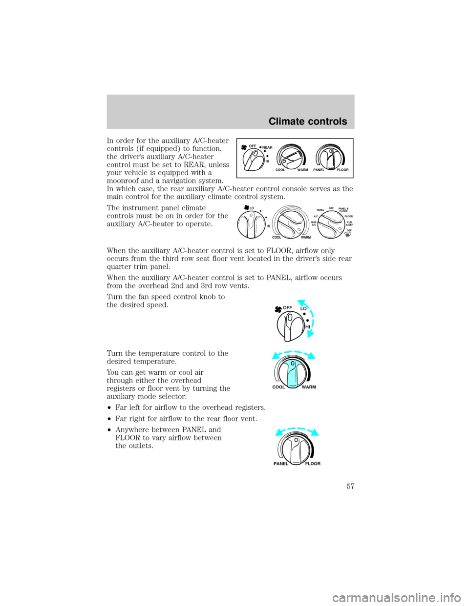
In order for the auxiliary A/C-heater
controls (if equipped) to function,
the driver's auxiliary A/C-heater
control must be set to REAR, unless
your vehicle is equipped with a
moonroof and a navigation system.
In which case, the rear auxiliary A/C-heater control console serves as the
main control for the auxiliary climate control system.
The instrument panel climate
controls must be on in order for the
auxiliary A/C-heater to operate.
When the auxiliary A/C-heater control is set to FLOOR, airflow only
occurs from the third row seat floor vent located in the driver's side rear
quarter trim panel.
When the auxiliary A/C-heater control is set to PANEL, airflow occurs
from the overhead 2nd and 3rd row vents.
Turn the fan speed control knob to
the desired speed.
Turn the temperature control to the
desired temperature.
You can get warm or cool air
through either the overhead
registers or floor vent by turning the
auxiliary mode selector:
²Far left for airflow to the overhead registers.
²Far right for airflow to the rear floor vent.
²Anywhere between PANEL and
FLOOR to vary airflow between
the outlets.
WARM PANEL FLOOR COOL
REAR OFF
HI
HI
COOL WARM
OFFPANELFLOOR
DEFFLR
& DEF A/C
MAX
A/CPANEL &
FLOOR
LO
LO OFF
HI
WARM COOL
FLOOR PANEL
Climate controls
57
Page 78 of 280
Press theportion of the VENT control to open the power rear
quarter windows.
Press the
portion of the VENT control to close the power rear
quarter windows.
AUXILIARY POWER POINT
Power outlets are designed for
accessory plugs only. Do not
hang any type of accessory or
accessory bracket from the plug.
Improper use of the power
outlet can cause damage not
covered by your warranty.
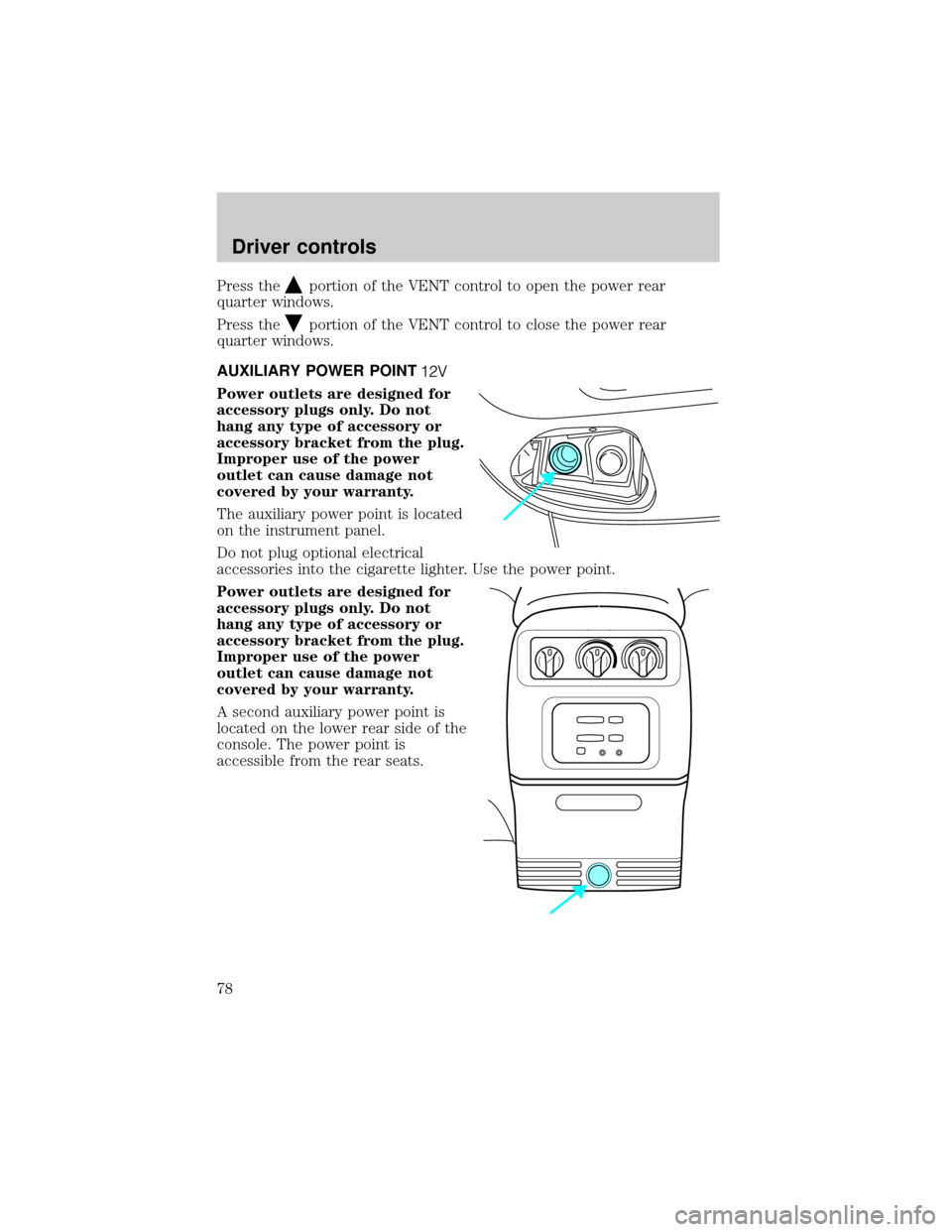
The auxiliary power point is located
on the instrument panel.
Do not plug optional electrical
accessories into the cigarette lighter. Use the power point.
Power outlets are designed for
accessory plugs only. Do not
hang any type of accessory or
accessory bracket from the plug.
Improper use of the power
outlet can cause damage not
covered by your warranty.
A second auxiliary power point is
located on the lower rear side of the
console. The power point is
accessible from the rear seats.
Driver controls
78
Page 182 of 280
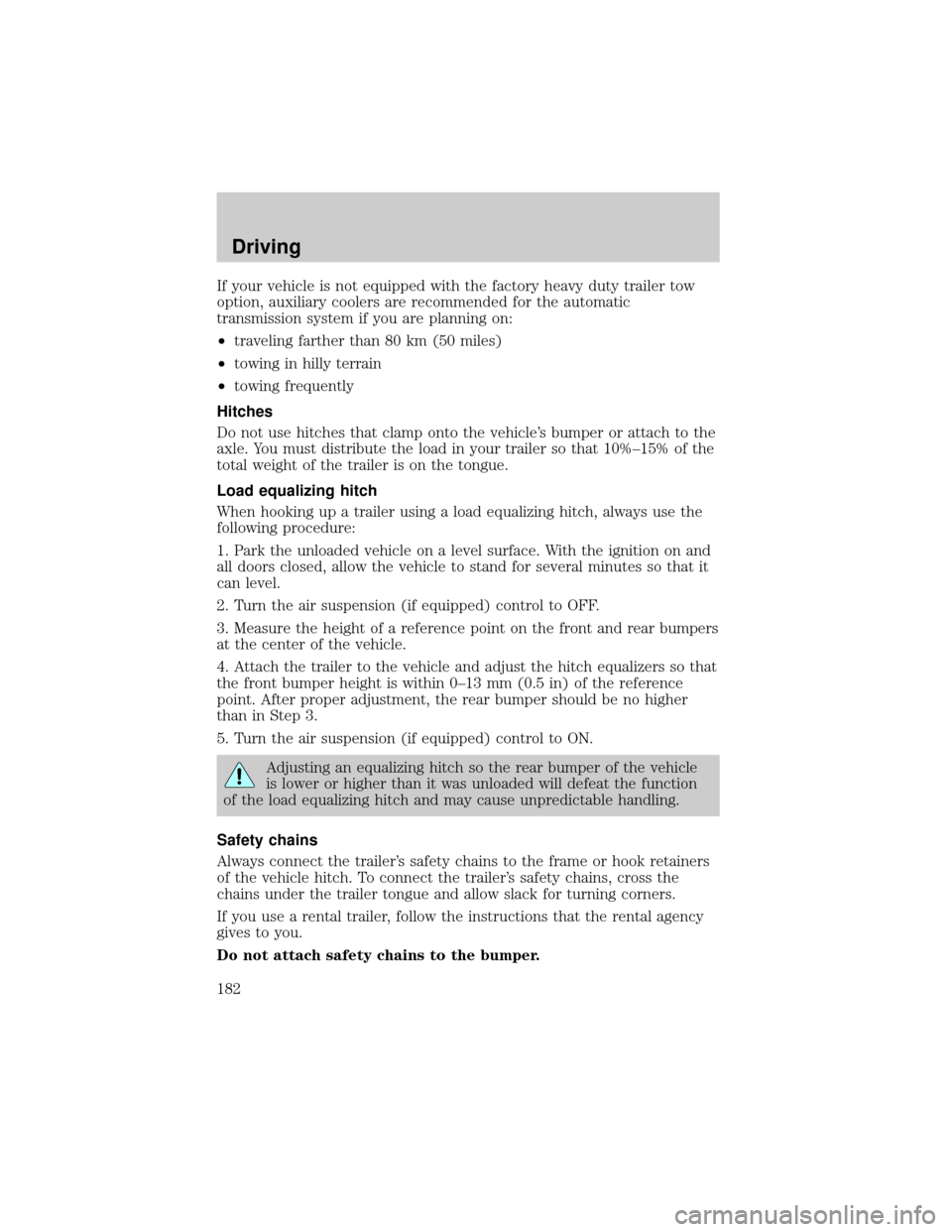
If your vehicle is not equipped with the factory heavy duty trailer tow
option, auxiliary coolers are recommended for the automatic
transmission system if you are planning on:
²traveling farther than 80 km (50 miles)
²towing in hilly terrain
²towing frequently
Hitches
Do not use hitches that clamp onto the vehicle's bumper or attach to the
axle. You must distribute the load in your trailer so that 10%±15% of the
total weight of the trailer is on the tongue.
Load equalizing hitch
When hooking up a trailer using a load equalizing hitch, always use the
following procedure:
1. Park the unloaded vehicle on a level surface. With the ignition on and
all doors closed, allow the vehicle to stand for several minutes so that it
can level.
2. Turn the air suspension (if equipped) control to OFF.
3. Measure the height of a reference point on the front and rear bumpers
at the center of the vehicle.
4. Attach the trailer to the vehicle and adjust the hitch equalizers so that
the front bumper height is within 0±13 mm (0.5 in) of the reference
point. After proper adjustment, the rear bumper should be no higher
than in Step 3.
5. Turn the air suspension (if equipped) control to ON.
Adjusting an equalizing hitch so the rear bumper of the vehicle
is lower or higher than it was unloaded will defeat the function
of the load equalizing hitch and may cause unpredictable handling.
Safety chains
Always connect the trailer's safety chains to the frame or hook retainers
of the vehicle hitch. To connect the trailer's safety chains, cross the
chains under the trailer tongue and allow slack for turning corners.
If you use a rental trailer, follow the instructions that the rental agency
gives to you.
Do not attach safety chains to the bumper.
Driving
182
Page 191 of 280
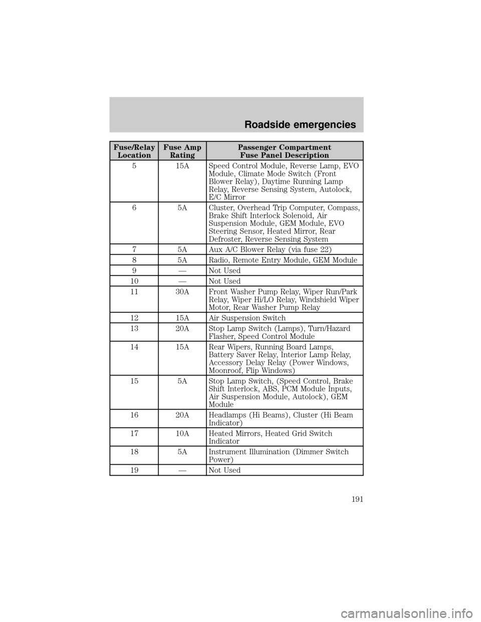
Fuse/Relay
LocationFuse Amp
RatingPassenger Compartment
Fuse Panel Description
5 15A Speed Control Module, Reverse Lamp, EVO
Module, Climate Mode Switch (Front
Blower Relay), Daytime Running Lamp
Relay, Reverse Sensing System, Autolock,
E/C Mirror
6 5A Cluster, Overhead Trip Computer, Compass,
Brake Shift Interlock Solenoid, Air
Suspension Module, GEM Module, EVO
Steering Sensor, Heated Mirror, Rear
Defroster, Reverse Sensing System
7 5A Aux A/C Blower Relay (via fuse 22)
8 5A Radio, Remote Entry Module, GEM Module
9 Ð Not Used
10 Ð Not Used
11 30A Front Washer Pump Relay, Wiper Run/Park
Relay, Wiper Hi/LO Relay, Windshield Wiper
Motor, Rear Washer Pump Relay
12 15A Air Suspension Switch
13 20A Stop Lamp Switch (Lamps), Turn/Hazard
Flasher, Speed Control Module
14 15A Rear Wipers, Running Board Lamps,
Battery Saver Relay, Interior Lamp Relay,
Accessory Delay Relay (Power Windows,
Moonroof, Flip Windows)
15 5A Stop Lamp Switch, (Speed Control, Brake
Shift Interlock, ABS, PCM Module Inputs,
Air Suspension Module, Autolock), GEM
Module
16 20A Headlamps (Hi Beams), Cluster (Hi Beam
Indicator)
17 10A Heated Mirrors, Heated Grid Switch
Indicator
18 5A Instrument Illumination (Dimmer Switch
Power)
19 Ð Not Used
Roadside emergencies
191
Page 192 of 280
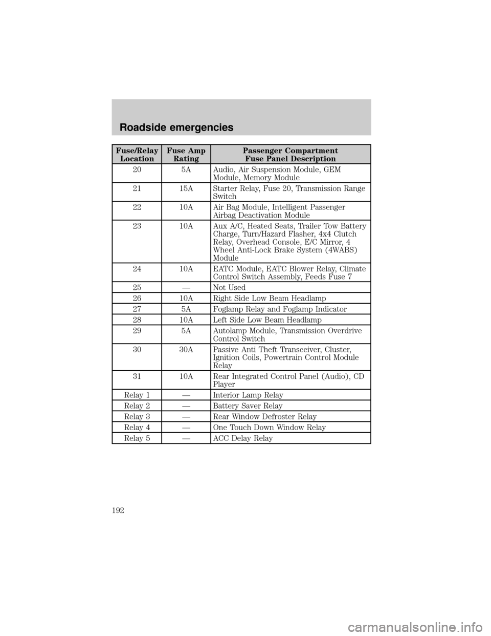
Fuse/Relay
LocationFuse Amp
RatingPassenger Compartment
Fuse Panel Description
20 5A Audio, Air Suspension Module, GEM
Module, Memory Module
21 15A Starter Relay, Fuse 20, Transmission Range
Switch
22 10A Air Bag Module, Intelligent Passenger
Airbag Deactivation Module
23 10A Aux A/C, Heated Seats, Trailer Tow Battery
Charge, Turn/Hazard Flasher, 4x4 Clutch
Relay, Overhead Console, E/C Mirror, 4
Wheel Anti-Lock Brake System (4WABS)
Module
24 10A EATC Module, EATC Blower Relay, Climate
Control Switch Assembly, Feeds Fuse 7
25 Ð Not Used
26 10A Right Side Low Beam Headlamp
27 5A Foglamp Relay and Foglamp Indicator
28 10A Left Side Low Beam Headlamp
29 5A Autolamp Module, Transmission Overdrive
Control Switch
30 30A Passive Anti Theft Transceiver, Cluster,
Ignition Coils, Powertrain Control Module
Relay
31 10A Rear Integrated Control Panel (Audio), CD
Player
Relay 1 Ð Interior Lamp Relay
Relay 2 Ð Battery Saver Relay
Relay 3 Ð Rear Window Defroster Relay
Relay 4 Ð One Touch Down Window Relay
Relay 5 Ð ACC Delay Relay
Roadside emergencies
192
Page 195 of 280
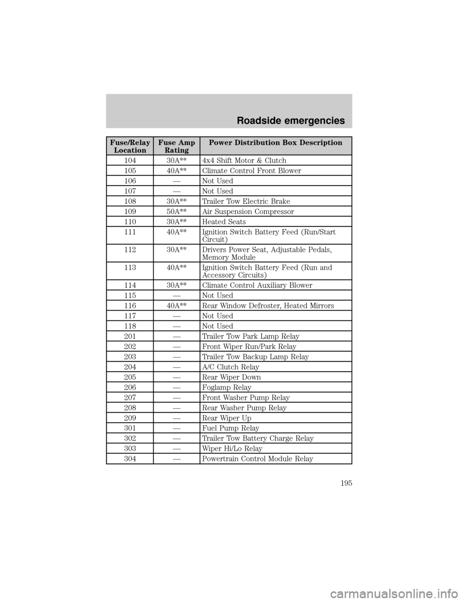
Fuse/Relay
LocationFuse Amp
RatingPower Distribution Box Description
104 30A** 4x4 Shift Motor & Clutch
105 40A** Climate Control Front Blower
106 Ð Not Used
107 Ð Not Used
108 30A** Trailer Tow Electric Brake
109 50A** Air Suspension Compressor
110 30A** Heated Seats
111 40A** Ignition Switch Battery Feed (Run/Start
Circuit)
112 30A** Drivers Power Seat, Adjustable Pedals,
Memory Module
113 40A** Ignition Switch Battery Feed (Run and
Accessory Circuits)
114 30A** Climate Control Auxiliary Blower
115 Ð Not Used
116 40A** Rear Window Defroster, Heated Mirrors
117 Ð Not Used
118 Ð Not Used
201 Ð Trailer Tow Park Lamp Relay
202 Ð Front Wiper Run/Park Relay
203 Ð Trailer Tow Backup Lamp Relay
204 Ð A/C Clutch Relay
205 Ð Rear Wiper Down
206 Ð Foglamp Relay
207 Ð Front Washer Pump Relay
208 Ð Rear Washer Pump Relay
209 Ð Rear Wiper Up
301 Ð Fuel Pump Relay
302 Ð Trailer Tow Battery Charge Relay
303 Ð Wiper Hi/Lo Relay
304 Ð Powertrain Control Module Relay
Roadside emergencies
195
Page 226 of 280
Working with the engine off
1. Set the parking brake and ensure the gearshift is securely latched in P
(Park).
2. Turn off the engine and remove the key.
3. Block the wheels to prevent the vehicle from moving unexpectedly.
Working with the engine on
1. Set the parking brake and ensure the gearshift is securely latched in P
(Park).
2. Block the wheels to prevent the vehicle from moving unexpectedly.
Note:Do not start your engine with the air cleaner removed and do not
remove it while the engine is running.
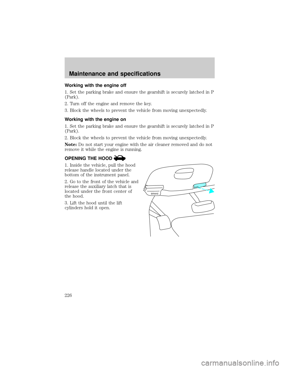
OPENING THE HOOD
1. Inside the vehicle, pull the hood
release handle located under the
bottom of the instrument panel.
2. Go to the front of the vehicle and
release the auxiliary latch that is
located under the front center of
the hood.
3. Lift the hood until the lift
cylinders hold it open.
BRAKE
HOOD
Maintenance and specifications
226
Page 261 of 280
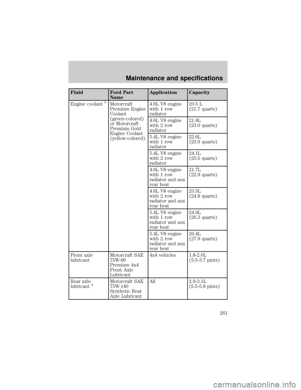
Fluid Ford Part
NameApplication Capacity
Engine coolant
3Motorcraft
Premium Engine
Coolant
(green-colored)
or Motorcraft
Premium Gold
Engine Coolant
(yellow-colored)4.6L V8 engine
with 1 row
radiator20.5 L
(21.7 quarts)
4.6L V8 engine
with 2 row
radiator21.8L
(23.0 quarts)
5.4L V8 engine
with 1 row
radiator22.6L
(23.9 quarts)
5.4L V8 engine
with 2 row
radiator24.1L
(25.5 quarts)
4.6L V8 engine
with 1 row
radiator and aux
rear heat21.7L
(22.9 quarts)
4.6L V8 engine
with 2 row
radiator and aux
rear heat23.5L
(24.8 quarts)
5.4L V8 engine
with 1 row
radiator and aux
rear heat24.9L
(26.3 quarts)
5.4L V8 engine
with 2 row
radiator and aux
rear heat26.4L
(27.9 quarts)
Front axle
lubricantMotorcraft SAE
75W-90
Premium 4x4
Front Axle
Lubricant4x4 vehicles 1.8-2.0L
(3.5-3.7 pints)
Rear axle
lubricant
4Motorcraft SAE
75W-140
Synthetic Rear
Axle LubricantAll 2.9-3.1L
(5.5-5.8 pints)
Maintenance and specifications
261