wiring FORD EXPEDITION 2003 2.G Owners Manual
[x] Cancel search | Manufacturer: FORD, Model Year: 2003, Model line: EXPEDITION, Model: FORD EXPEDITION 2003 2.GPages: 320, PDF Size: 3.67 MB
Page 87 of 320
Replacing the interior bulbs
Check the operation of all bulbs frequently.
Map lamps
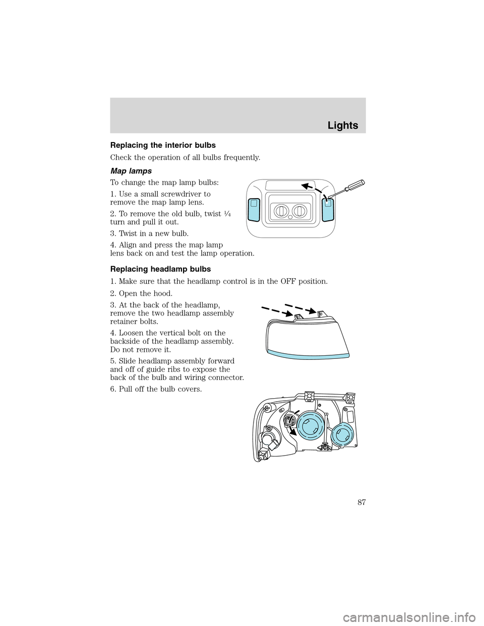
To change the map lamp bulbs:
1. Use a small screwdriver to
remove the map lamp lens.
2. To remove the old bulb, twist
1⁄4
turn and pull it out.
3. Twist in a new bulb.
4. Align and press the map lamp
lens back on and test the lamp operation.
Replacing headlamp bulbs
1. Make sure that the headlamp control is in the OFF position.
2. Open the hood.
3. At the back of the headlamp,
remove the two headlamp assembly
retainer bolts.
4. Loosen the vertical bolt on the
backside of the headlamp assembly.
Do not remove it.
5. Slide headlamp assembly forward
and off of guide ribs to expose the
back of the bulb and wiring connector.
6. Pull off the bulb covers.
Lights
87
Page 156 of 320
•Front safety belts with pretensioners, energy management retractors,
and safety belt usage sensors.
•Driver’s seat position sensor.
•Front crash severity sensor.
•Restraints Control Module (RCM) with impact and safing sensors.
•Restraint system warning light and back-up tone.
•The electrical wiring for the air bags, crash sensor(s), safety belt
pretensioners, front safety belt usage sensors, driver seat position
sensor, and indicator lights.
How does the personal safety system work?
The Personal Safety System can adapt the deployment strategy of your
vehicle’s safety devices according to crash severity and occupant
conditions. A collection of crash and occupant sensors provides
information to the Restraints Control Module (RCM). During a crash, the
RCM activates the safety belt pretensioners and/or either one or both
stages of the dual-stage air bag supplemental restraints based on crash
severity and occupant conditions.
The fact that the pretensioners or air bags did not activate for both front
seat occupants in a collision does not mean that something is wrong with
the system. Rather, it means the Personal Safety System determined the
accident conditions (crash severity, belt usage, etc.) were not
appropriate to activate these safety devices. Front air bags are designed
to activate only in frontal and near-frontal collisions, not rollovers,
side-impacts, or rear-impacts unless the collision causes sufficient
longitudinal deceleration.
Driver and passenger dual-stage air bag supplemental restraints
The dual-stage air bags offer the capability to tailor the level of air bag
inflation energy. A lower, less forceful energy level is provided for more
common, moderate-severity impacts. A higher energy level is used for
the most severe impacts. Refer toAir bag Supplemental Restraints
section in this chapter.
Front crash severity sensor
The front crash severity sensor enhances the ability to detect the
severity of an impact. Positioned up front, it provides valuable
information early in the crash event on the severity of the impact. This
allows your Personal Safety System to distinguish between different
levels of crash severity and modify the deployment strategy of the
dual-stage air bags and safety belt pretensioners.
Seating and Safety Restraints
156
Page 172 of 320
Several air bag system components get hot after inflation. Do not
touch them after inflation.
If the air bag has deployed,the air bag will not function
again and must be replaced immediately.If the air bag is not
replaced, the unrepaired area will increase the risk of injury in a
collision.
The SRS consists of:
•driver and passenger air bag modules (which include the inflators and
air bags),
•one or more impact and safing sensors and diagnostic monitor (RCM),
•a readiness light and tone
•the electrical wiring which connects the components.
The RCM (restraints control module) monitors its own internal circuits
and the supplemental air bag electrical system warning (including the
impact sensors, the system wiring, the air bag system readiness light, the
air bag back up power and the air bag ignitors).
Determining if the system is operational
The SRS uses a readiness light in the instrument cluster or a tone to
indicate the condition of the system. Refer toAir bag readinesssection
in theInstrument clusterchapter. Routine maintenance of the air bag is
not required.
A difficulty with the system is indicated by one or more of the following:
•The readiness light will either
flash or stay lit.
•The readiness light will not
illuminate immediately after ignition is turned on.
•A series of five beeps will be heard. The tone pattern will repeat
periodically until the problem and/or light are repaired.
If any of these things happen, even intermittently, have the SRS serviced
at your dealership or by a qualified technician immediately. Unless
serviced, the system may not function properly in the event of a
collision.
Seating and Safety Restraints
172
Page 222 of 320
•Thoroughly prepare your vehicle for towing. Refer toPreparing to
towin this chapter.
•Use extra caution when driving while trailer towing. Refer toDriving
while you towin this chapter.
•Service your vehicle more frequently if you tow a trailer. Refer to the
severe duty schedule in the scheduled maintenance guide.
•Do not tow a trailer until your vehicle has been driven at least 800 km
(500 miles).
•Refer to the instructions included with towing accessories for the
proper installation and adjustment specifications.
Your vehicle is equipped with heavy duty trailer tow wiring. An electrical
connector is provided under the instrument panel for installing a
customer-supplied electric brake controller. A Class I (4–pin) electrical
connector and Class II/III/IV (7–pin) electrical connector are provided at
the hitch. These connectors provide power to the trailer for taillamps,
stop and turn lamps, back up lamps, battery charge, electric brakes
(when a customer provided controller is installed) and ground. A kit
containing a wiring harness/adapter and installation instructions to attach
an electric brake controller may be obtained from any Ford or
Lincoln/Mercury dealer (part number 5A416). Before towing a trailer,
make sure the trailer brakes (if equipped) and lamps are properly
connected and functional. Refer to the brake controller instructions to
check for trailer brake functionality.
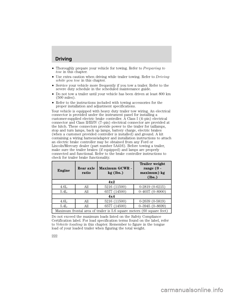
EngineRear axle
ratioMaximum GCWR -
kg (lbs.)Trailer weight
range (0 -
maximum) kg
(lbs.)
4x2
4.6L All 5216 (11500) 0-2819 (0-6215)
5.4L All 6577 (14500) 0–4037 (0–8900)
4x4
4.6L All 5216 (11500) 0-2639 (0-5819)
5.4L All 6577 (14500) 0–3945 (0–8699)
Maximum frontal area of trailer is 5.6 square meters (60 square feet)
Do not exceed the maximum loads listed on the Safety Compliance
Certification label. For load specification terms found on the label, refer
toVehicle loadingin this chapter. Remember to figure in the tongue
load of your loaded trailer when figuring the total weight.
Driving
222
Page 226 of 320
Launching or retrieving a boat
Disconnect the wiring to the trailer before backing the trailer
into the water. Reconnect the wiring to the trailer after the
trailer is removed from the water.
When backing down a ramp during boat launching or retrieval:
•do not allow the static water level to rise above the bottom edge of
the rear bumper.
•do not allow waves to break higher than 15 cm (6 inches) above the
bottom edge of the rear bumper.
Exceeding these limits may allow water to enter vehicle components:
•causing internal damage to the components.
•affecting driveability, emissions and reliability.
Replace the rear axle lubricant any time the axle has been submerged in
water. Rear axle lubricant quantities are not to be checked or changed
unless a leak is suspected or repair required.
RECREATIONAL TOWING (ALL WHEELS ON THE GROUND)
An example of recreational towing would be towing your vehicle behind a
motorhome. Follow these guidelines if you have the need for recreational
towing your vehicle with all four wheels on the ground. These guidelines
are designed to ensure that your transmission is not damaged.
2WD vehicles (with automatic transmissions):
•Place the transmission in N (Neutral)
•Maximum speed is 56 km (35 mph)
•Maximum distance is 80 km (50 miles)
If a distance of 80 km (50 miles) or a speed of 56 km (35 mph) must be
exceeded, the drive shaft will have to be removed before the vehicle is
towed.
Ford recommends the driveshaft be removed/installed only by a qualified
technician. See your local dealer for driveshaft removal/installation.
Improper removal/installation of the driveshaft can cause
transmission fluid loss, damage to the driveshaft and internal
transmission components.
Vehicles equipped with Control Trac four-wheel drive system:
Vehicles equipped with the Control Trac four-wheel drive system cannot be
towed with any wheels on the ground. See your local dealer if you must
flat-tow a vehicle equipped with the Control Trac four-wheel drive system.
Driving
226
Page 299 of 320
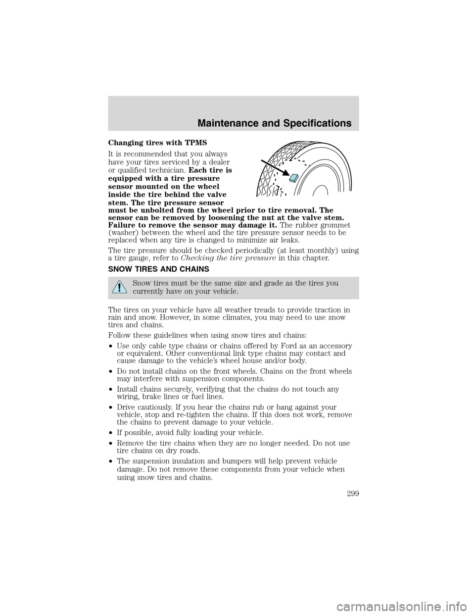
Changing tires with TPMS
It is recommended that you always
have your tires serviced by a dealer
or qualified technician.Each tire is
equipped with a tire pressure
sensor mounted on the wheel
inside the tire behind the valve
stem. The tire pressure sensor
must be unbolted from the wheel prior to tire removal. The
sensor can be removed by loosening the nut at the valve stem.
Failure to remove the sensor may damage it.The rubber grommet
(washer) between the wheel and the tire pressure sensor needs to be
replaced when any tire is changed to minimize air leaks.
The tire pressure should be checked periodically (at least monthly) using
a tire gauge, refer toChecking the tire pressurein this chapter.
SNOW TIRES AND CHAINS
Snow tires must be the same size and grade as the tires you
currently have on your vehicle.
The tires on your vehicle have all weather treads to provide traction in
rain and snow. However, in some climates, you may need to use snow
tires and chains.
Follow these guidelines when using snow tires and chains:
•Use only cable type chains or chains offered by Ford as an accessory
or equivalent. Other conventional link type chains may contact and
cause damage to the vehicle’s wheel house and/or body.
•Do not install chains on the front wheels. Chains on the front wheels
may interfere with suspension components.
•Install chains securely, verifying that the chains do not touch any
wiring, brake lines or fuel lines.
•Drive cautiously. If you hear the chains rub or bang against your
vehicle, stop and re-tighten the chains. If this does not work, remove
the chains to prevent damage to your vehicle.
•If possible, avoid fully loading your vehicle.
•Remove the tire chains when they are no longer needed. Do not use
tire chains on dry roads.
•The suspension insulation and bumpers will help prevent vehicle
damage. Do not remove these components from your vehicle when
using snow tires and chains.
Maintenance and Specifications
299