sensor FORD EXPEDITION 2016 3.G Owner's Manual
[x] Cancel search | Manufacturer: FORD, Model Year: 2016, Model line: EXPEDITION, Model: FORD EXPEDITION 2016 3.GPages: 421, PDF Size: 6.3 MB
Page 194 of 421
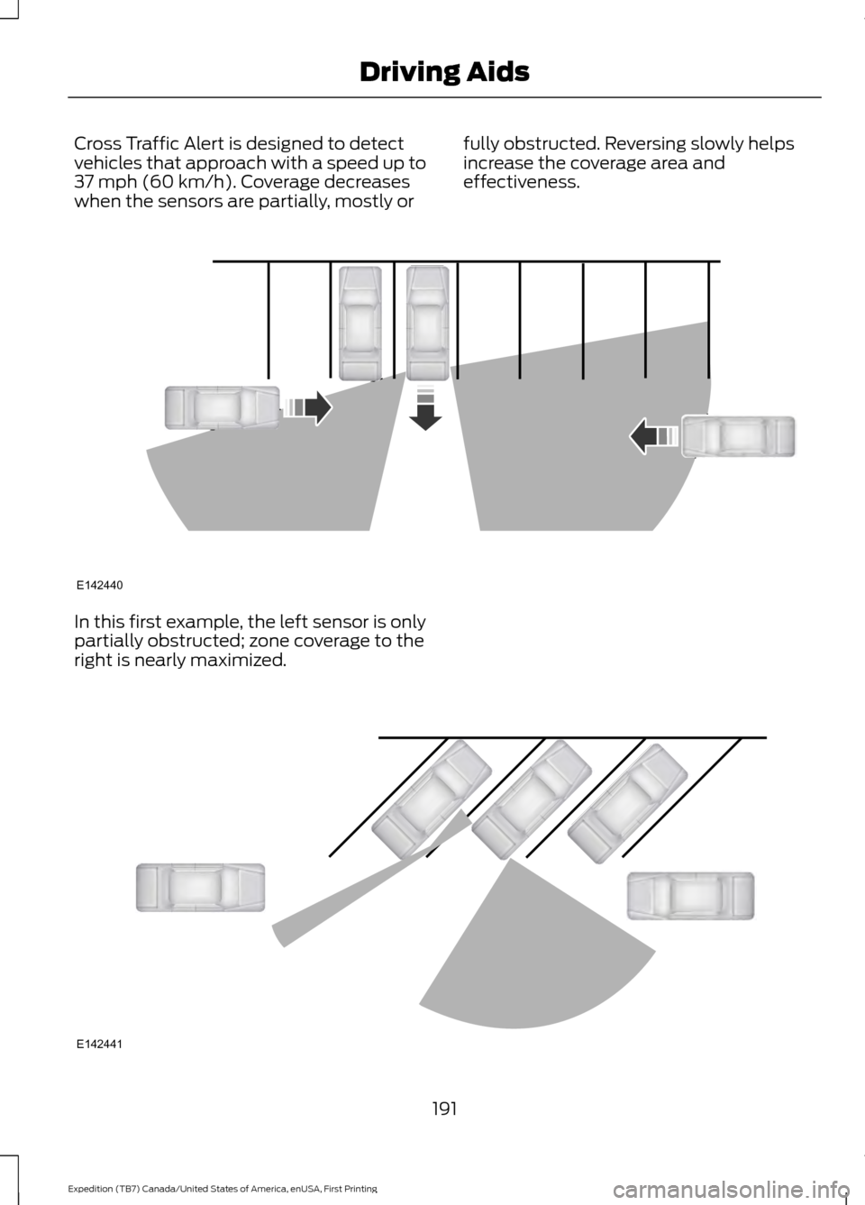
Cross Traffic Alert is designed to detect
vehicles that approach with a speed up to
37 mph (60 km/h). Coverage decreases
when the sensors are partially, mostly or fully obstructed. Reversing slowly helps
increase the coverage area and
effectiveness.In this first example, the left sensor is only
partially obstructed; zone coverage to the
right is nearly maximized.
191
Expedition (TB7) Canada/United States of America, enUSA, First Printing Driving AidsE142440 E142441
Page 195 of 421
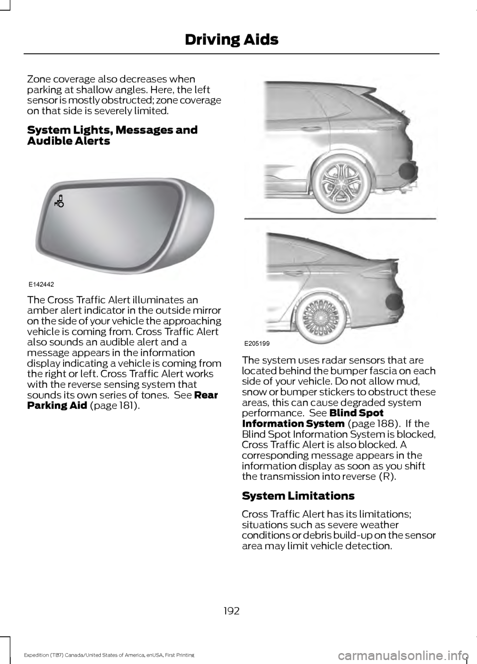
Zone coverage also decreases when
parking at shallow angles. Here, the left
sensor is mostly obstructed; zone coverage
on that side is severely limited.
System Lights, Messages and
Audible Alerts
The Cross Traffic Alert illuminates an
amber alert indicator in the outside mirror
on the side of your vehicle the approaching
vehicle is coming from. Cross Traffic Alert
also sounds an audible alert and a
message appears in the information
display indicating a vehicle is coming from
the right or left. Cross Traffic Alert works
with the reverse sensing system that
sounds its own series of tones. See Rear
Parking Aid (page 181). The system uses radar sensors that are
located behind the bumper fascia on each
side of your vehicle. Do not allow mud,
snow or bumper stickers to obstruct these
areas, this can cause degraded system
performance. See Blind Spot
Information System (page 188). If the
Blind Spot Information System is blocked,
Cross Traffic Alert is also blocked. A
corresponding message appears in the
information display as soon as you shift
the transmission into reverse (R).
System Limitations
Cross Traffic Alert has its limitations;
situations such as severe weather
conditions or debris build-up on the sensor
area may limit vehicle detection.
192
Expedition (TB7) Canada/United States of America, enUSA, First Printing Driving AidsE142442 E205199
Page 196 of 421
The following are other situations that may
limit the Cross Traffic Alert performance:
•
Adjacently parked vehicles or objects
obstructing the sensors.
• Approaching vehicles passing at
speeds greater than 37 mph
(60 km/h).
• Driving in reverse faster than
7 mph
(12 km/h).
• Backing out of an angled parking spot.
False Alerts
Note: If your vehicle has a tow bar with a
factory equipped trailer tow module and it
is towing a trailer, the sensors will
automatically turn the Cross Traffic Alert
off. If your vehicle has a tow bar but no
factory equipped trailer tow module, it is
recommended to turn the Cross Traffic Alert
off manually. Operating Cross Traffic Alert
with a trailer attached will cause poor Cross
Traffic Alert performance.
There may be certain instances when there
is a false alert by the Cross Traffic Alert
system that illuminates the alert indicator
with no vehicle in the coverage zone. Some
amount of false alerts are normal; they are
temporary and self-correct.
System Errors
If Cross Traffic Alert senses a problem with
the left or right sensor a message will
appear in the information display. See
Information Messages
(page 103).
Switching the System Off and On
You can temporarily switch Cross Traffic
Alert off in the information display. See
General Information
(page 92). When
you switch Cross Traffic Alert off, you will
not receive alerts and the information
display will display a system off message. Note:
The Cross Traffic Alert switches on
whenever the ignition is switched on and
ready to provide appropriate alerts when
the transmission is in reverse (R). Cross
Traffic Alert will not remember the last
selected on or off setting.
You can also have Cross Traffic Alert
switched off permanently at an authorized
dealer. Once switched off permanently,
the system can only be switched back on
at an authorized dealer.
STEERING
Electric Power Steering WARNINGS
The electric power steering system
has diagnostic checks that
continuously monitor the system. If
a fault is detected, a message displays in
the information display. Stop your vehicle
as soon as it is safe to do so. Switch the
ignition off. After at least 10 seconds,
switch the ignition on and watch the
information display for a steering system
warning message. If a steering system
warning message returns, have the system
checked by an authorized dealer. If the system detects an error, you
may not feel a difference in the
steering, however a serious condition
may exist. Obtain immediate service from
an authorized dealer, failure to do so may
result in loss of steering control. Your vehicle has an electric power steering
system. There is no fluid reservoir. No
maintenance is required.
If your vehicle loses electrical power while
you are driving, electric power steering
assistance is lost. The steering system still
operates and you can steer your vehicle
manually. Manually steering your vehicle
requires more effort.
193
Expedition (TB7) Canada/United States of America, enUSA, First Printing Driving Aids
Page 238 of 421
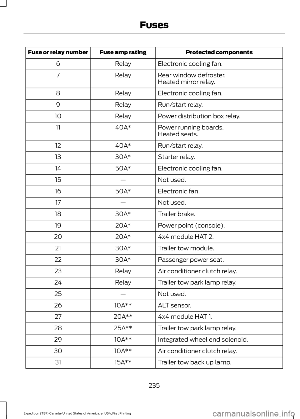
Protected components
Fuse amp rating
Fuse or relay number
Electronic cooling fan.
Relay
6
Rear window defroster.
Relay
7
Heated mirror relay.
Electronic cooling fan.
Relay
8
Run/start relay.
Relay
9
Power distribution box relay.
Relay
10
Power running boards.
40A*
11
Heated seats.
Run/start relay.
40A*
12
Starter relay.
30A*
13
Electronic cooling fan.
50A*
14
Not used.
—
15
Electronic fan.
50A*
16
Not used.
—
17
Trailer brake.
30A*
18
Power point (console).
20A*
19
4x4 module HAT 2.
20A*
20
Trailer tow module.
30A*
21
Passenger power seat.
30A*
22
Air conditioner clutch relay.
Relay
23
Trailer tow park lamp relay.
Relay
24
Not used.
—
25
ALT sensor.
10A**
26
4x4 module HAT 1.
20A**
27
Trailer tow park lamp relay.
25A**
28
Integrated wheel end solenoid.
10A**
29
Air conditioner clutch relay.
10A**
30
Trailer tow back up lamp.
15A**
31
235
Expedition (TB7) Canada/United States of America, enUSA, First Printing Fuses
Page 241 of 421
Protected components
Fuse amp rating
Fuse or relay number
Not used.
—
81
Rain sensor.
5A**
82
Not used.
—
83
Not used.
—
84
Wiper motor relay.
Relay
85
*Cartridge fuses.
**Mini fuses.
Passenger Compartment Fuse
Panel
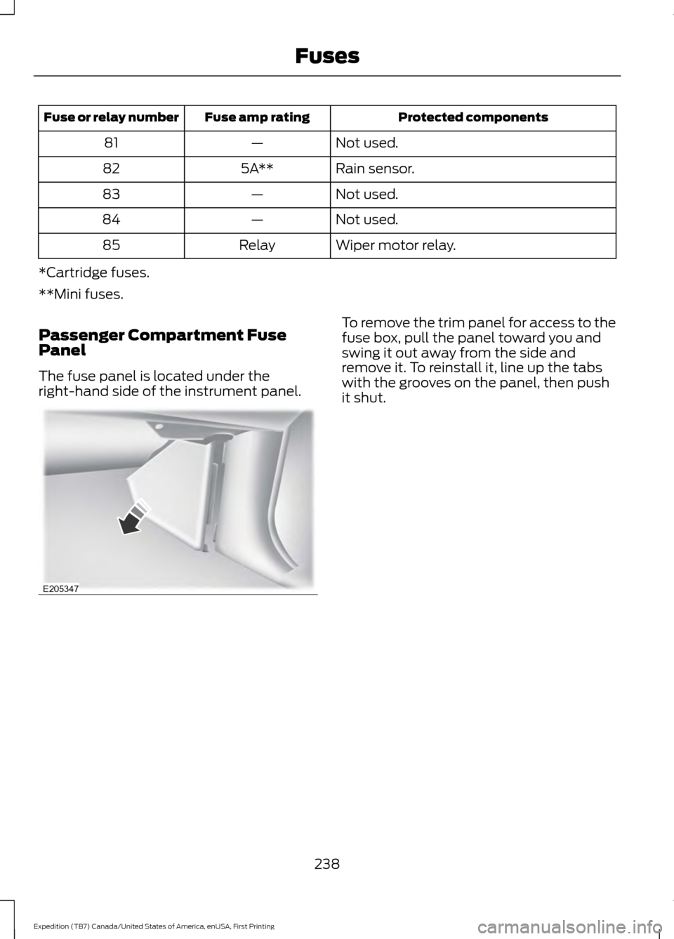
The fuse panel is located under the
right-hand side of the instrument panel. To remove the trim panel for access to the
fuse box, pull the panel toward you and
swing it out away from the side and
remove it. To reinstall it, line up the tabs
with the grooves on the panel, then push
it shut.
238
Expedition (TB7) Canada/United States of America, enUSA, First Printing FusesE205347
Page 265 of 421
CHANGING THE ENGINE AIR
FILTER
WARNING
To reduce the risk of vehicle damage
and personal burn injuries, do not
start your engine with the air cleaner
removed and do not remove it while the
engine is running. Note:
Failure to use the correct air filter
element may result in severe engine
damage. Resulting component damage
may not be covered by the vehicle Warranty.
When changing the air filter element, use
only the air filter element listed. See
Motorcraft Parts (page 303).
Change the air filter element at the correct
interval. See
Scheduled Maintenance
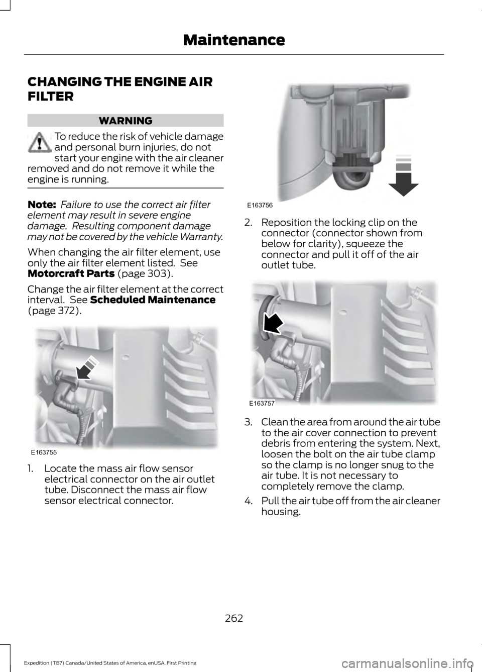
(page 372). 1. Locate the mass air flow sensor
electrical connector on the air outlet
tube. Disconnect the mass air flow
sensor electrical connector. 2. Reposition the locking clip on the
connector (connector shown from
below for clarity), squeeze the
connector and pull it off of the air
outlet tube. 3.
Clean the area from around the air tube
to the air cover connection to prevent
debris from entering the system. Next,
loosen the bolt on the air tube clamp
so the clamp is no longer snug to the
air tube. It is not necessary to
completely remove the clamp.
4. Pull the air tube off from the air cleaner
housing.
262
Expedition (TB7) Canada/United States of America, enUSA, First Printing MaintenanceE163755 E163756 E163757
Page 266 of 421
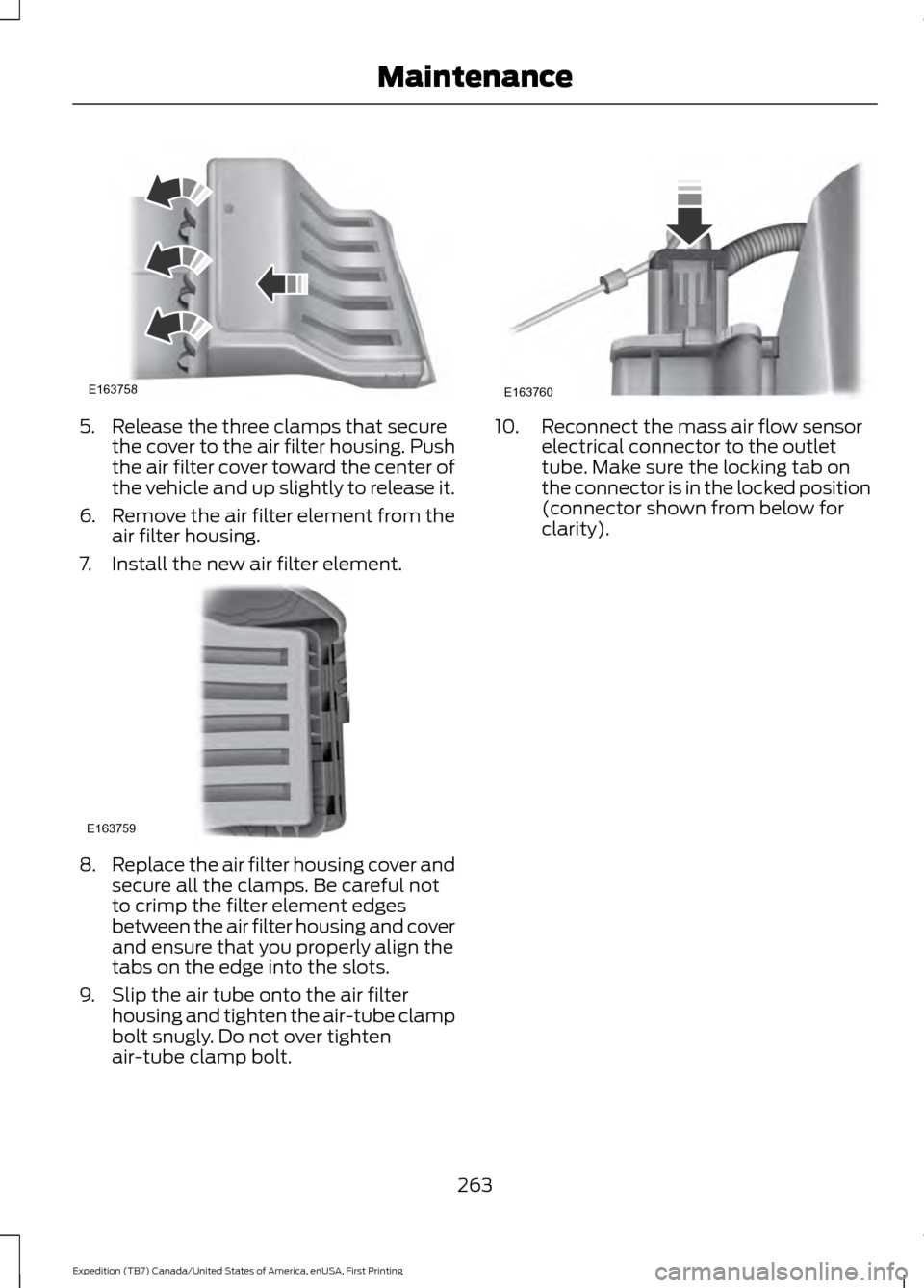
5. Release the three clamps that secure
the cover to the air filter housing. Push
the air filter cover toward the center of
the vehicle and up slightly to release it.
6. Remove the air filter element from the
air filter housing.
7. Install the new air filter element. 8.
Replace the air filter housing cover and
secure all the clamps. Be careful not
to crimp the filter element edges
between the air filter housing and cover
and ensure that you properly align the
tabs on the edge into the slots.
9. Slip the air tube onto the air filter housing and tighten the air-tube clamp
bolt snugly. Do not over tighten
air-tube clamp bolt. 10. Reconnect the mass air flow sensor
electrical connector to the outlet
tube. Make sure the locking tab on
the connector is in the locked position
(connector shown from below for
clarity).
263
Expedition (TB7) Canada/United States of America, enUSA, First Printing MaintenanceE163758 E163759 E163760
Page 290 of 421
WARNINGS
not recommended by Ford can
affect the safety and performance
of your vehicle, which could result
in an increased risk of loss of
vehicle control, vehicle rollover,
personal injury and death.
Additionally the use of
non-recommended tires and
wheels could cause steering,
suspension, axle, transfer case or
power transfer unit failure. If you
have questions regarding tire
replacement, contact your
authorized dealer as soon as
possible. To reduce the risk of serious
injury, when mounting
replacement tires and wheels, you
should not exceed the maximum
pressure indicated on the sidewall
of the tire to set the beads without
additional precautions listed
below. If the beads do not seat at
the maximum pressure indicated,
re-lubricate and try again.
When inflating the tire for
mounting pressures up to 20 psi
(1.38 bar) greater than the
maximum pressure on the tire
sidewall, the following
precautions must be taken to
protect the person mounting the
tire:
1. Make sure that you have the
correct tire and wheel size.
2. Lubricate the tire bead and
wheel bead seat area again. WARNINGS
3. Stand at a minimum of
12 ft
(3.6 m) away from the wheel and
tire assembly.
4. Use both eye and ear
protection.
For a mounting pressure more
than 20 psi (1.38 bar) greater than
the maximum pressure, a Ford
dealer or other tire service
professional should do the
mounting.
Always inflate steel carcass tires
with a remote air fill with the
person inflating standing at a
minimum of
12 ft (3.6 m) away
from the wheel and tire assembly. Important: Remember to replace
the wheel valve stems when the
road tires are replaced on your
vehicle.
The two front tires or two rear tires
should generally be replaced as a
pair.
The tire pressure sensors mounted
in the wheels are not designed to
be used in aftermarket wheels.
The use of wheels or tires not
recommended by Ford Motor
Company may affect the
operation of your tire pressure
monitoring system.
287
Expedition (TB7) Canada/United States of America, enUSA, First Printing Wheels and Tires
Page 292 of 421
Wheel misalignment in the front
or the rear can cause uneven and
rapid treadwear of your tires and
should be corrected by an
authorized dealer. Front-wheel
drive vehicles and those with an
independent rear suspension may
require alignment of all four
wheels.
The tires should also be balanced
periodically. An unbalanced tire
and wheel assembly may result in
irregular tire wear.
Tire Rotation
WARNING
If the tire label shows
different tire pressures for the
front and rear tires and the vehicle
is equipped with a tire pressure
monitoring system, then the
settings for the system sensors
need to be updated. Always
perform the system reset
procedure after tire rotation. If the
system is not reset, it may not
provide a low tire pressure
warning when necessary. See the
tire pressure monitoring system
reset procedure in this chapter. Note:
If your tires show uneven
wear ask an authorized dealer to
check for and correct any wheel
misalignment, tire imbalance or
mechanical problem involved
before tire rotation. Note:
Your vehicle may be
equipped with a dissimilar spare
wheel and tire assembly. A
dissimilar spare wheel and tire
assembly is defined as a spare
wheel and tire assembly that is
different in brand, size or
appearance from the road tires and
wheels. If you have a dissimilar
spare wheel and tire assembly it is
intended for temporary use only
and should not be used in a tire
rotation.
Note: After having your tires
rotated, inflation pressure must be
checked and adjusted to the
vehicle requirements.
Rotating your tires at the
recommended interval (as
indicated in the Scheduled
Maintenance chapter) will help
your tires wear more evenly,
providing better tire performance
and longer tire life.
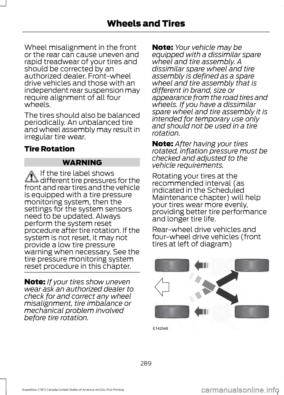
Rear-wheel drive vehicles and
four-wheel drive vehicles (front
tires at left of diagram) 289
Expedition (TB7) Canada/United States of America, enUSA, First Printing Wheels and TiresE142548
Page 295 of 421
Changing Tires With a Tire
Pressure Monitoring System
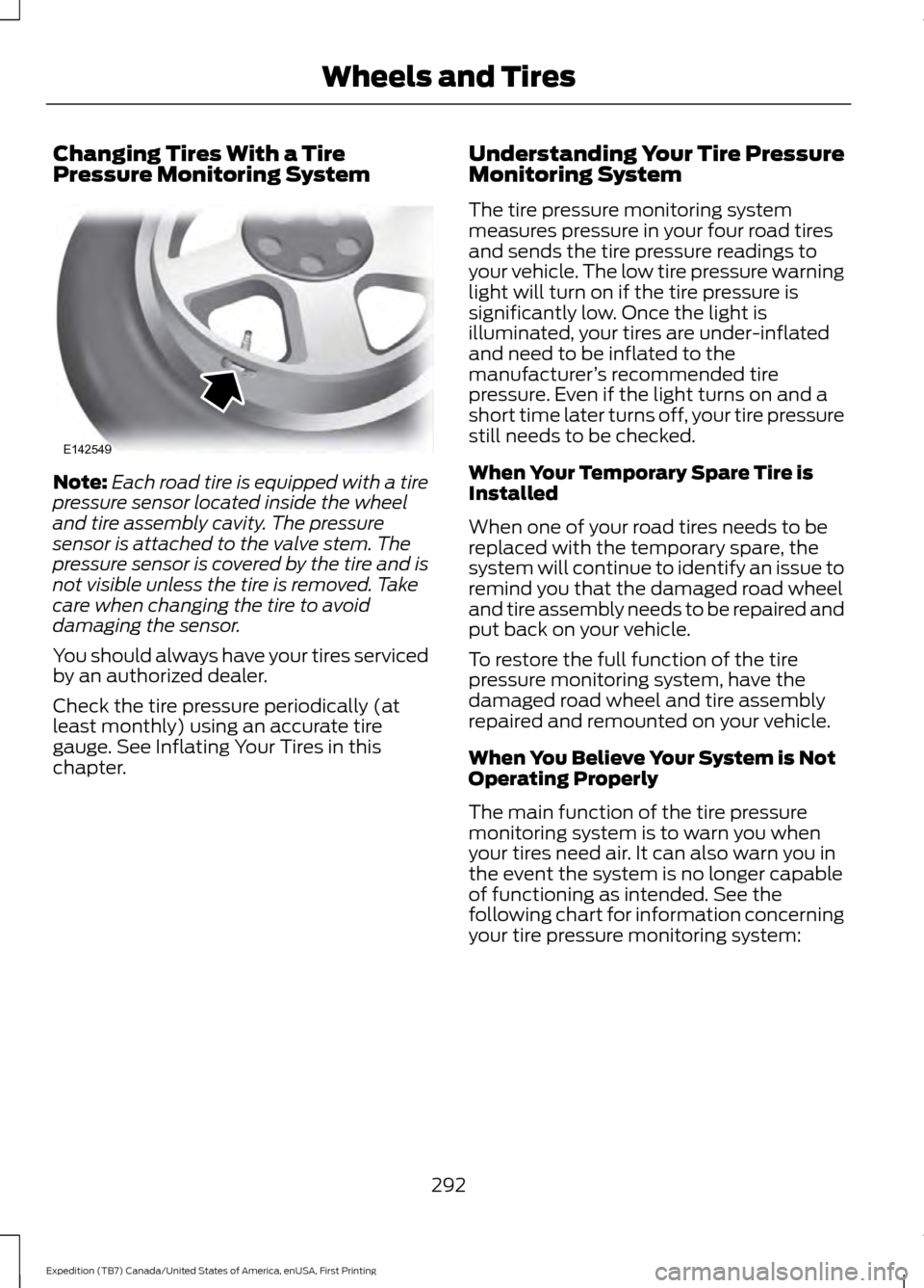
Note:
Each road tire is equipped with a tire
pressure sensor located inside the wheel
and tire assembly cavity. The pressure
sensor is attached to the valve stem. The
pressure sensor is covered by the tire and is
not visible unless the tire is removed. Take
care when changing the tire to avoid
damaging the sensor.
You should always have your tires serviced
by an authorized dealer.
Check the tire pressure periodically (at
least monthly) using an accurate tire
gauge. See Inflating Your Tires in this
chapter. Understanding Your Tire Pressure
Monitoring System
The tire pressure monitoring system
measures pressure in your four road tires
and sends the tire pressure readings to
your vehicle. The low tire pressure warning
light will turn on if the tire pressure is
significantly low. Once the light is
illuminated, your tires are under-inflated
and need to be inflated to the
manufacturer
’s recommended tire
pressure. Even if the light turns on and a
short time later turns off, your tire pressure
still needs to be checked.
When Your Temporary Spare Tire is
Installed
When one of your road tires needs to be
replaced with the temporary spare, the
system will continue to identify an issue to
remind you that the damaged road wheel
and tire assembly needs to be repaired and
put back on your vehicle.
To restore the full function of the tire
pressure monitoring system, have the
damaged road wheel and tire assembly
repaired and remounted on your vehicle.
When You Believe Your System is Not
Operating Properly
The main function of the tire pressure
monitoring system is to warn you when
your tires need air. It can also warn you in
the event the system is no longer capable
of functioning as intended. See the
following chart for information concerning
your tire pressure monitoring system:
292
Expedition (TB7) Canada/United States of America, enUSA, First Printing Wheels and TiresE142549