tow bar FORD EXPEDITION EL 2017 Owners Manual
[x] Cancel search | Manufacturer: FORD, Model Year: 2017, Model line: EXPEDITION EL, Model: FORD EXPEDITION EL 2017Pages: 500, PDF Size: 6.13 MB
Page 97 of 500
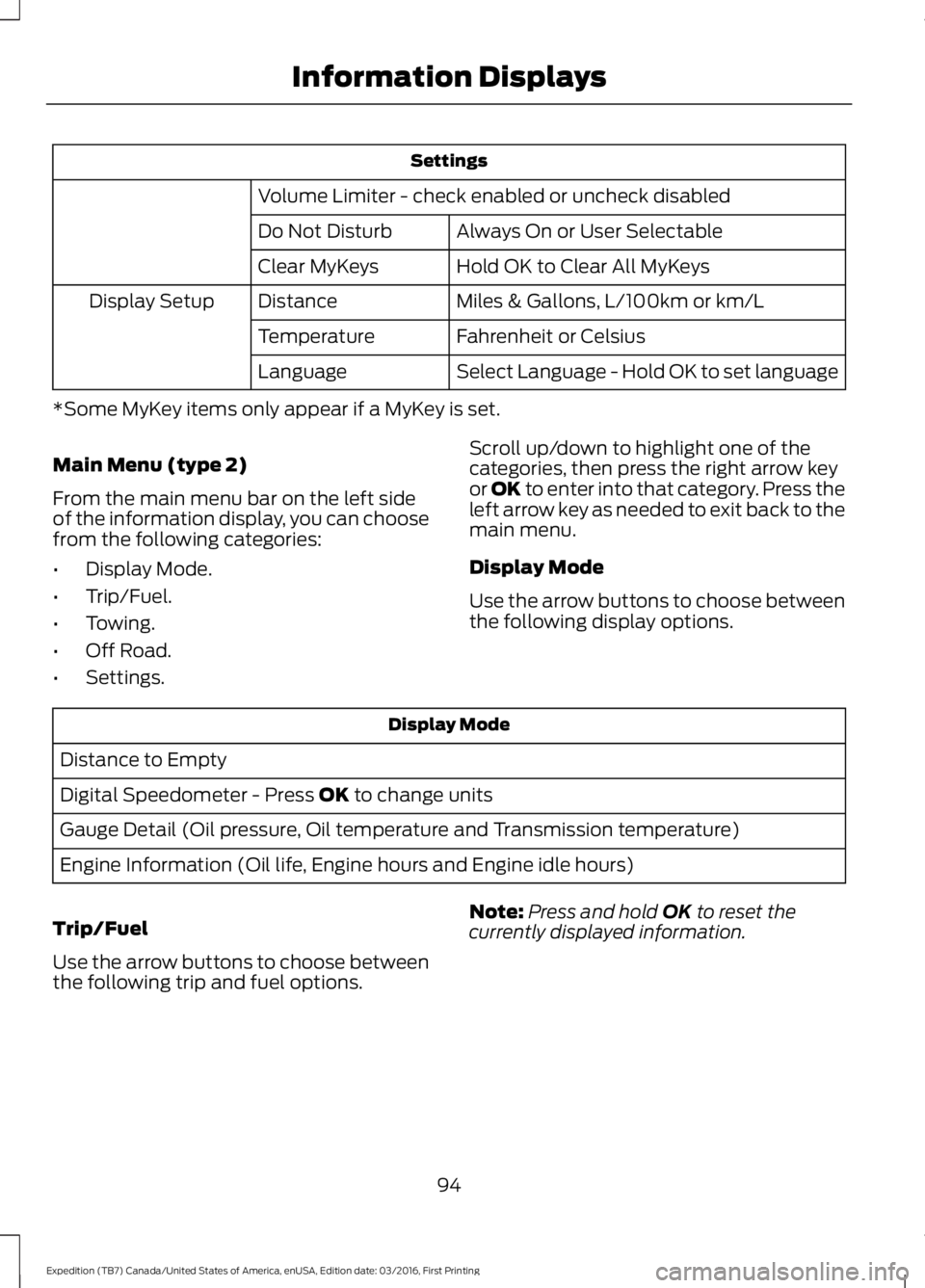
Settings
Volume Limiter - check enabled or uncheck disabled
Always On or User SelectableDo Not Disturb
Hold OK to Clear All MyKeysClear MyKeys
Miles & Gallons, L/100km or km/LDistanceDisplay Setup
Fahrenheit or CelsiusTemperature
Select Language - Hold OK to set languageLanguage
*Some MyKey items only appear if a MyKey is set.
Main Menu (type 2)
From the main menu bar on the left sideof the information display, you can choosefrom the following categories:
•Display Mode.
•Trip/Fuel.
•Towing.
•Off Road.
•Settings.
Scroll up/down to highlight one of thecategories, then press the right arrow keyor OK to enter into that category. Press theleft arrow key as needed to exit back to themain menu.
Display Mode
Use the arrow buttons to choose betweenthe following display options.
Display Mode
Distance to Empty
Digital Speedometer - Press OK to change units
Gauge Detail (Oil pressure, Oil temperature and Transmission temperature)
Engine Information (Oil life, Engine hours and Engine idle hours)
Trip/Fuel
Use the arrow buttons to choose betweenthe following trip and fuel options.
Note:Press and hold OK to reset thecurrently displayed information.
94
Expedition (TB7) Canada/United States of America, enUSA, Edition date: 03/2016, First Printing
Information Displays
Page 98 of 500
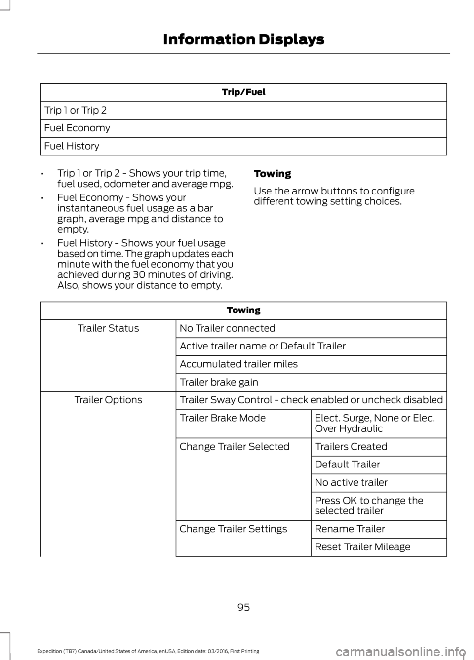
Trip/Fuel
Trip 1 or Trip 2
Fuel Economy
Fuel History
•Trip 1 or Trip 2 - Shows your trip time,fuel used, odometer and average mpg.
•Fuel Economy - Shows yourinstantaneous fuel usage as a bargraph, average mpg and distance toempty.
•Fuel History - Shows your fuel usagebased on time. The graph updates eachminute with the fuel economy that youachieved during 30 minutes of driving.Also, shows your distance to empty.
Towing
Use the arrow buttons to configuredifferent towing setting choices.
Towing
No Trailer connectedTrailer Status
Active trailer name or Default Trailer
Accumulated trailer miles
Trailer brake gain
Trailer Sway Control - check enabled or uncheck disabledTrailer Options
Elect. Surge, None or Elec.Over HydraulicTrailer Brake Mode
Trailers CreatedChange Trailer Selected
Default Trailer
No active trailer
Press OK to change theselected trailer
Rename TrailerChange Trailer Settings
Reset Trailer Mileage
95
Expedition (TB7) Canada/United States of America, enUSA, Edition date: 03/2016, First Printing
Information Displays
Page 101 of 500
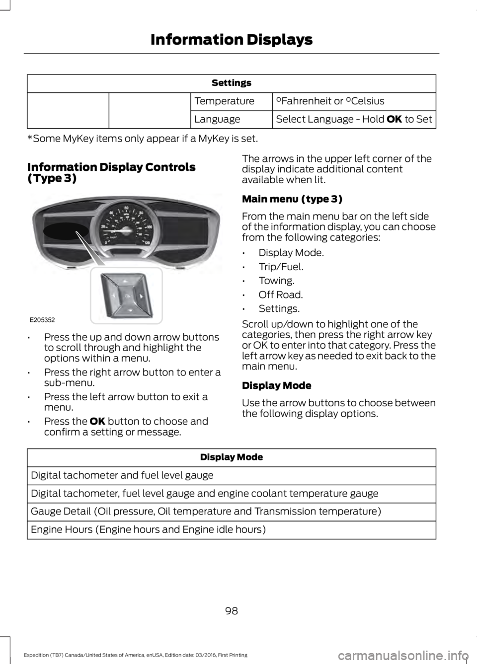
Settings
°Fahrenheit or °CelsiusTemperature
Select Language - Hold OK to SetLanguage
*Some MyKey items only appear if a MyKey is set.
Information Display Controls(Type 3)
•Press the up and down arrow buttonsto scroll through and highlight theoptions within a menu.
•Press the right arrow button to enter asub-menu.
•Press the left arrow button to exit amenu.
•Press the OK button to choose andconfirm a setting or message.
The arrows in the upper left corner of thedisplay indicate additional contentavailable when lit.
Main menu (type 3)
From the main menu bar on the left sideof the information display, you can choosefrom the following categories:
•Display Mode.
•Trip/Fuel.
•Towing.
•Off Road.
•Settings.
Scroll up/down to highlight one of thecategories, then press the right arrow keyor OK to enter into that category. Press theleft arrow key as needed to exit back to themain menu.
Display Mode
Use the arrow buttons to choose betweenthe following display options.
Display Mode
Digital tachometer and fuel level gauge
Digital tachometer, fuel level gauge and engine coolant temperature gauge
Gauge Detail (Oil pressure, Oil temperature and Transmission temperature)
Engine Hours (Engine hours and Engine idle hours)
98
Expedition (TB7) Canada/United States of America, enUSA, Edition date: 03/2016, First Printing
Information DisplaysE205352
Page 102 of 500
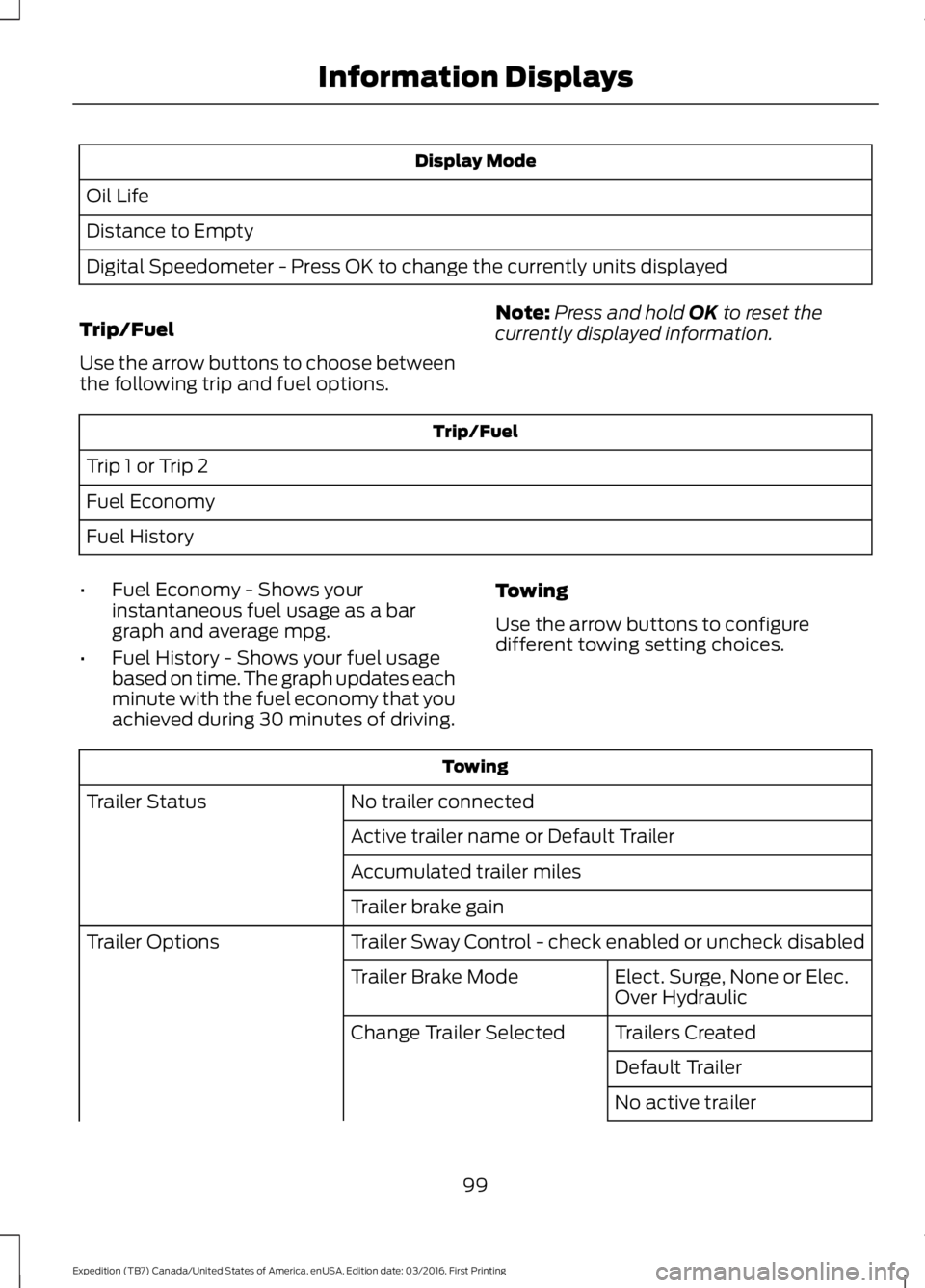
Display Mode
Oil Life
Distance to Empty
Digital Speedometer - Press OK to change the currently units displayed
Trip/Fuel
Use the arrow buttons to choose betweenthe following trip and fuel options.
Note:Press and hold OK to reset thecurrently displayed information.
Trip/Fuel
Trip 1 or Trip 2
Fuel Economy
Fuel History
•Fuel Economy - Shows yourinstantaneous fuel usage as a bargraph and average mpg.
•Fuel History - Shows your fuel usagebased on time. The graph updates eachminute with the fuel economy that youachieved during 30 minutes of driving.
Towing
Use the arrow buttons to configuredifferent towing setting choices.
Towing
No trailer connectedTrailer Status
Active trailer name or Default Trailer
Accumulated trailer miles
Trailer brake gain
Trailer Sway Control - check enabled or uncheck disabledTrailer Options
Elect. Surge, None or Elec.Over HydraulicTrailer Brake Mode
Trailers CreatedChange Trailer Selected
Default Trailer
No active trailer
99
Expedition (TB7) Canada/United States of America, enUSA, Edition date: 03/2016, First Printing
Information Displays
Page 208 of 500
Note:Certain states requireelectric trailer brakes for trailersover a specified weight. Be sure tocheck state regulations for thisspecified weight. The maximumtrailer weights listed may be limitedto this specified weight, as thevehicle’s electrical system may notinclude the wiring connectorneeded to activate electric trailerbrakes.
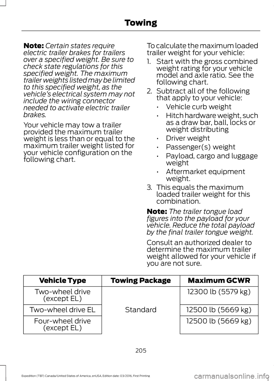
Your vehicle may tow a trailerprovided the maximum trailerweight is less than or equal to themaximum trailer weight listed foryour vehicle configuration on thefollowing chart.
To calculate the maximum loadedtrailer weight for your vehicle:
1. Start with the gross combinedweight rating for your vehiclemodel and axle ratio. See thefollowing chart.
2.Subtract all of the followingthat apply to your vehicle:
•Vehicle curb weight
•Hitch hardware weight, suchas a draw bar, ball, locks orweight distributing
•Driver weight
•Passenger(s) weight
•Payload, cargo and luggageweight
•Aftermarket equipmentweight.
3.This equals the maximumloaded trailer weight for thiscombination.
Note:The trailer tongue loadfigures into the payload for yourvehicle. Reduce the total payloadby the final trailer tongue weight.
Consult an authorized dealer todetermine the maximum trailerweight allowed for your vehicle ifyou are not sure.
Maximum GCWRTowing PackageVehicle Type
12300 lb (5579 kg)
Standard
Two-wheel drive(except EL)
12500 lb (5669 kg)Two-wheel drive EL
12500 lb (5669 kg)Four-wheel drive(except EL)
205
Expedition (TB7) Canada/United States of America, enUSA, Edition date: 03/2016, First Printing
Towing
Page 211 of 500
Integrated Hitch Rating
WARNING
Towing trailers beyond the maximumtongue weight exceeds the limit ofthe towing system and could resultin vehicle structural damage, loss of vehiclecontrol and personal injury.
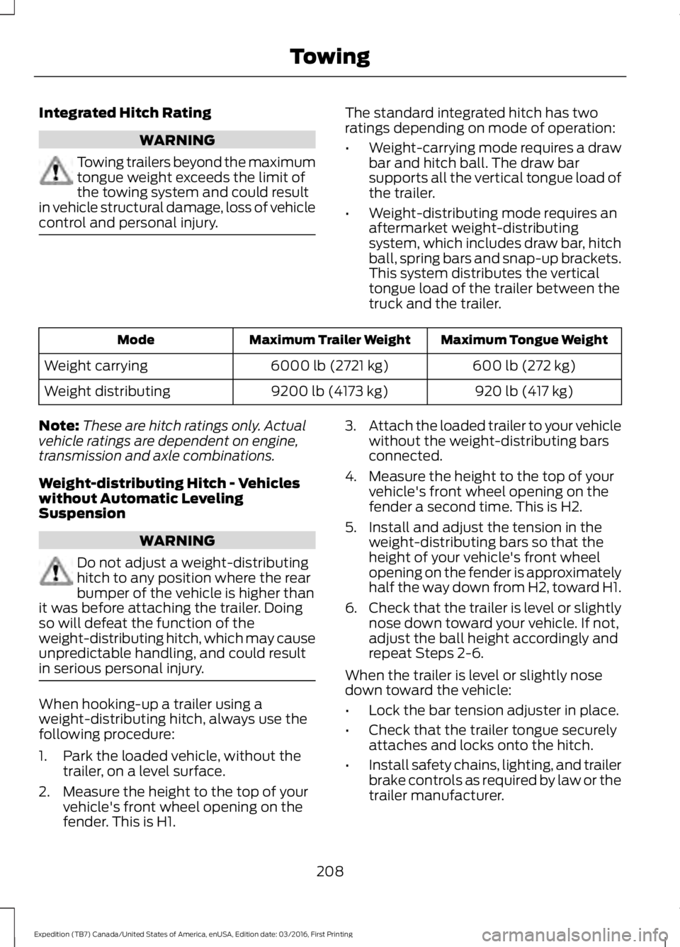
The standard integrated hitch has tworatings depending on mode of operation:
•Weight-carrying mode requires a drawbar and hitch ball. The draw barsupports all the vertical tongue load ofthe trailer.
•Weight-distributing mode requires anaftermarket weight-distributingsystem, which includes draw bar, hitchball, spring bars and snap-up brackets.This system distributes the verticaltongue load of the trailer between thetruck and the trailer.
Maximum Tongue WeightMaximum Trailer WeightMode
600 lb (272 kg)6000 lb (2721 kg)Weight carrying
920 lb (417 kg)9200 lb (4173 kg)Weight distributing
Note:These are hitch ratings only. Actualvehicle ratings are dependent on engine,transmission and axle combinations.
Weight-distributing Hitch - Vehicleswithout Automatic LevelingSuspension
WARNING
Do not adjust a weight-distributinghitch to any position where the rearbumper of the vehicle is higher thanit was before attaching the trailer. Doingso will defeat the function of theweight-distributing hitch, which may causeunpredictable handling, and could resultin serious personal injury.
When hooking-up a trailer using aweight-distributing hitch, always use thefollowing procedure:
1. Park the loaded vehicle, without thetrailer, on a level surface.
2. Measure the height to the top of yourvehicle's front wheel opening on thefender. This is H1.
3.Attach the loaded trailer to your vehiclewithout the weight-distributing barsconnected.
4. Measure the height to the top of yourvehicle's front wheel opening on thefender a second time. This is H2.
5. Install and adjust the tension in theweight-distributing bars so that theheight of your vehicle's front wheelopening on the fender is approximatelyhalf the way down from H2, toward H1.
6.Check that the trailer is level or slightlynose down toward your vehicle. If not,adjust the ball height accordingly andrepeat Steps 2-6.
When the trailer is level or slightly nosedown toward the vehicle:
•Lock the bar tension adjuster in place.
•Check that the trailer tongue securelyattaches and locks onto the hitch.
•Install safety chains, lighting, and trailerbrake controls as required by law or thetrailer manufacturer.
208
Expedition (TB7) Canada/United States of America, enUSA, Edition date: 03/2016, First Printing
Towing
Page 212 of 500
Weight-distributing Hitch - Vehicleswith Automatic Leveling Suspension
WARNING
Do not adjust a weight-distributinghitch to any position where the rearbumper of the vehicle is higher thanit was before attaching the trailer. Doingso will defeat the function of theweight-distributing hitch, which may causeunpredictable handling, and could resultin serious personal injury.
Note:If you do not move the loaded vehiclefor approximately 12 hours, the levelingsystem may bleed down to a lower height.This can be especially apparent if you leavea trailer attached to the parked vehicle forlong periods. You must drive your vehicle inorder to re-level the suspension.
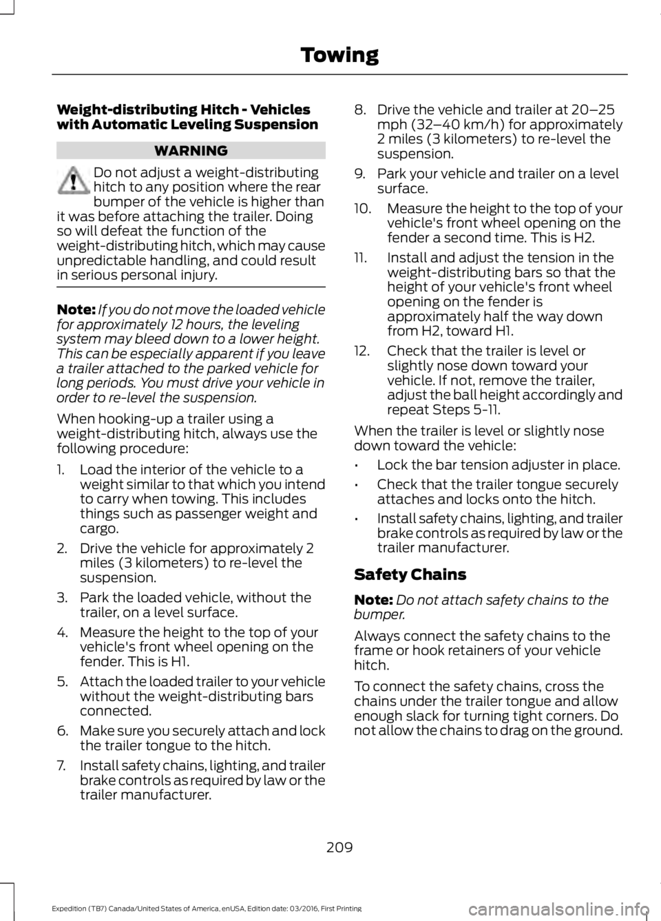
When hooking-up a trailer using aweight-distributing hitch, always use thefollowing procedure:
1. Load the interior of the vehicle to aweight similar to that which you intendto carry when towing. This includesthings such as passenger weight andcargo.
2. Drive the vehicle for approximately 2miles (3 kilometers) to re-level thesuspension.
3. Park the loaded vehicle, without thetrailer, on a level surface.
4. Measure the height to the top of yourvehicle's front wheel opening on thefender. This is H1.
5.Attach the loaded trailer to your vehiclewithout the weight-distributing barsconnected.
6.Make sure you securely attach and lockthe trailer tongue to the hitch.
7.Install safety chains, lighting, and trailerbrake controls as required by law or thetrailer manufacturer.
8. Drive the vehicle and trailer at 20–25mph (32–40 km/h) for approximately2 miles (3 kilometers) to re-level thesuspension.
9. Park your vehicle and trailer on a levelsurface.
10.Measure the height to the top of yourvehicle's front wheel opening on thefender a second time. This is H2.
11. Install and adjust the tension in theweight-distributing bars so that theheight of your vehicle's front wheelopening on the fender isapproximately half the way downfrom H2, toward H1.
12. Check that the trailer is level orslightly nose down toward yourvehicle. If not, remove the trailer,adjust the ball height accordingly andrepeat Steps 5-11.
When the trailer is level or slightly nosedown toward the vehicle:
•Lock the bar tension adjuster in place.
•Check that the trailer tongue securelyattaches and locks onto the hitch.
•Install safety chains, lighting, and trailerbrake controls as required by law or thetrailer manufacturer.
Safety Chains
Note:Do not attach safety chains to thebumper.
Always connect the safety chains to theframe or hook retainers of your vehiclehitch.
To connect the safety chains, cross thechains under the trailer tongue and allowenough slack for turning tight corners. Donot allow the chains to drag on the ground.
209
Expedition (TB7) Canada/United States of America, enUSA, Edition date: 03/2016, First Printing
Towing
Page 214 of 500
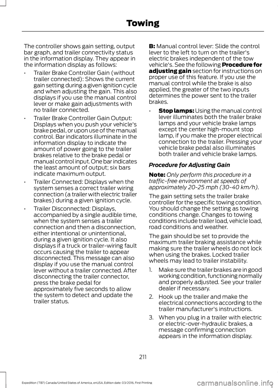
The controller shows gain setting, outputbar graph, and trailer connectivity statusin the information display. They appear inthe information display as follows:
•Trailer Brake Controller Gain (withouttrailer connected): Shows the currentgain setting during a given ignition cycleand when adjusting the gain. This alsodisplays if you use the manual controllever or make gain adjustments withno trailer connected.
•Trailer Brake Controller Gain Output:Displays when you push your vehicle'sbrake pedal, or upon use of the manualcontrol. Bar indicators illuminate in theinformation display to indicate theamount of power going to the trailerbrakes relative to the brake pedal ormanual control input. One bar indicatesthe least amount of output; six barsindicate maximum output.
•Trailer Connected: Displays when thesystem senses a correct trailer wiringconnection (a trailer with electric trailerbrakes) during a given ignition cycle.
•Trailer Disconnected: Displays,accompanied by a single audible time,when the system senses a trailerconnection and then a disconnection,either intentional or unintentional,during a given ignition cycle. It alsodisplays if a truck or trailer-wiring faultoccurs causing the trailer to appeardisconnected. This message can alsodisplay if you use the manual controllever without a trailer connected. Afterdisconnecting the trailer connector,press the brake pedal forapproximately five seconds to allowthe system to detect and update thetrailer status.
B: Manual control lever: Slide the controllever to the left to turn on the trailer'selectric brakes independent of the towvehicle's. See the following Procedure foradjusting gain section for instructions onproper use of this feature. If you use themanual control while the brake is alsoapplied, the greater of the two inputsdetermines the power sent to the trailerbrakes.
•Stop lamps: Using the manual controllever illuminates both the trailer brakelamps and your vehicle brake lampsexcept the center high-mount stoplamp, if you make the proper electricalconnection to the trailer. Pressing yourvehicle brake pedal also illuminatesboth trailer and vehicle brake lamps.
Procedure for Adjusting Gain
Note:Only perform this procedure in atraffic-free environment at speeds ofapproximately 20-25 mph (30-40 km/h).
The gain setting sets the trailer brakecontroller for the specific towing condition.You should change the setting as towingconditions change. Changes to towingconditions include trailer load, vehicle load,road conditions and weather.
The gain should be set to provide themaximum trailer braking assistance whilemaking sure the trailer wheels do not lockwhen using the brakes. Locked trailerwheels may lead to trailer instability.
1.Make sure the trailer brakes are in goodworking condition, functioning normallyand properly adjusted. See your trailerdealer if necessary.
2. Hook up the trailer and make theelectrical connections according to thetrailer manufacturer's instructions.
3. When you plug in a trailer with electricor electric-over-hydraulic brakes, amessage confirming connectionappears in the information display.
211
Expedition (TB7) Canada/United States of America, enUSA, Edition date: 03/2016, First Printing
Towing
Page 289 of 500
it needs to be repaired or replaced.For your safety, tires that aredamaged or show signs ofexcessive wear should not be usedbecause they are more likely toblow out or fail.
Improper or inadequate vehiclemaintenance can cause tires towear abnormally. Inspect all yourtires, including the spare,frequently, and replace them ifone or more of the followingconditions exist:
Tire Wear
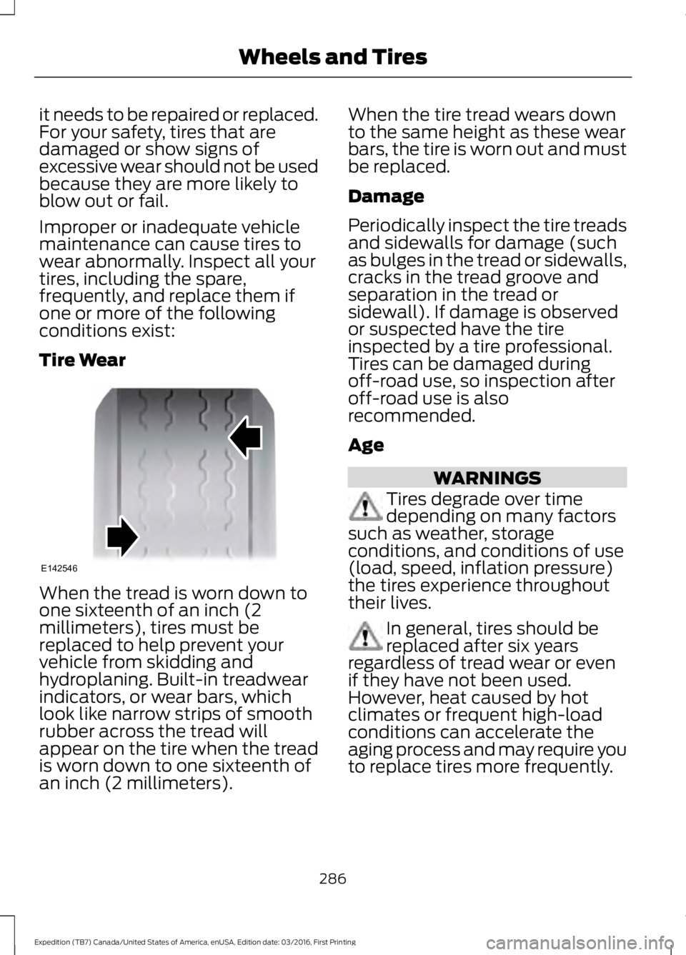
When the tread is worn down toone sixteenth of an inch (2millimeters), tires must bereplaced to help prevent yourvehicle from skidding andhydroplaning. Built-in treadwearindicators, or wear bars, whichlook like narrow strips of smoothrubber across the tread willappear on the tire when the treadis worn down to one sixteenth ofan inch (2 millimeters).
When the tire tread wears downto the same height as these wearbars, the tire is worn out and mustbe replaced.
Damage
Periodically inspect the tire treadsand sidewalls for damage (suchas bulges in the tread or sidewalls,cracks in the tread groove andseparation in the tread orsidewall). If damage is observedor suspected have the tireinspected by a tire professional.Tires can be damaged duringoff-road use, so inspection afteroff-road use is alsorecommended.
Age
WARNINGS
Tires degrade over timedepending on many factorssuch as weather, storageconditions, and conditions of use(load, speed, inflation pressure)the tires experience throughouttheir lives.
In general, tires should bereplaced after six yearsregardless of tread wear or evenif they have not been used.However, heat caused by hotclimates or frequent high-loadconditions can accelerate theaging process and may require youto replace tires more frequently.
286
Expedition (TB7) Canada/United States of America, enUSA, Edition date: 03/2016, First Printing
Wheels and TiresE142546
Page 496 of 500
Power Liftgate.................................................56Obstacle Detection.............................................58Opening and Closing the Liftgate...................57Stopping the Liftgate Movement...................58Power Running Boards................................63Power Seats....................................................124Power Lumbar......................................................125Power Recline......................................................124Power Windows..............................................79Accessory Delay....................................................79Bounce-Back.........................................................79One-Touch Down.................................................79One-Touch Up.......................................................79Window Lock.........................................................79Protecting the Environment........................15
R
Rear Axle...........................................................172Rear Parking Aid............................................182Obstacle Distance Indicator...........................183Rear Passenger Climate Controls...........119Rear Quarter Windows................................82Rear Seats.......................................................126Adjusting the Second Row Center 20%Seat......................................................................131Adjusting the Second Row Outboard 40%Seat for E-Z Entry..........................................128Exiting the Third Row........................................129Folding Down the Second Row 40% Seat..............................................................................126Folding Down the Third Row Seats to theLoad Floor..........................................................131Folding the Second Row Center 20% Seat..............................................................................130Placing the Second Row Outboard 40%Seats in Cargo Mode.....................................127PowerFold™ Third Row Seat.........................132Reclining the Second Row Outboard 40%Seatback...........................................................129Returning to the Upright Position from theFull Lowered Load Floor Position............128Third Row Seats...................................................131Rear Under Floor Storage.........................196Cargo Management System..........................196Cargo Shelf and Divider...................................196Third Row Storage Bin......................................197
Rear View Camera.......................................184Using the Rear View Camera System.........184Rear View CameraSee: Rear View Camera...................................184Rear Window Wiper and Washers...........72Rear Window Washer..........................................72Rear Window Wiper.............................................72Recommended Towing Weights...........204Reduced Engine Performance.................218Refueling..........................................................152System Warnings................................................154Remote Control..............................................43Car Finder................................................................45Integrated Keyhead Transmitter.....................43Intelligent Access Key.........................................43Memory Feature...................................................46Remote Start.........................................................45Replacing the Battery.........................................44Sounding the Panic Alarm................................45Remote Start.................................................120Automatic Settings............................................120Removing a Headlamp..............................257Repairing Minor Paint Damage...............270Replacement PartsRecommendation........................................12Collision Repairs....................................................12Scheduled Maintenance and MechanicalRepairs..................................................................12Warranty on Replacement Parts.....................12Replacing a Lost Key or RemoteControl............................................................46Reporting Safety Defects (CanadaOnly)...............................................................231Reporting Safety Defects (U.S.Only)...............................................................231Roadside Assistance...................................221Vehicles Sold in Canada: Getting RoadsideAssistance.........................................................221Vehicles Sold in Canada: RoadsideAssistance Program Coverage.................222Vehicles Sold in Canada: Using RoadsideAssistance........................................................222Vehicles Sold in the United States: GettingRoadside Assistance....................................221Vehicles Sold in the United States: UsingRoadside Assistance....................................221Roadside Emergencies...............................221
493
Expedition (TB7) Canada/United States of America, enUSA, Edition date: 03/2016, First Printing
Index