maintenance FORD EXPLORER 1997 2.G Owners Manual
[x] Cancel search | Manufacturer: FORD, Model Year: 1997, Model line: EXPLORER, Model: FORD EXPLORER 1997 2.GPages: 236, PDF Size: 2.43 MB
Page 1 of 236
Before driving
Introduction 2
Instrumentation 5
Controls and features 25
Seating and safety restraints 78
Starting and driving
Starting 110
Driving 117
Roadside emergencies 147
Servicing
Maintenance and care 165
Capacities and specifications 222
Reporting safety defects 232
Index 233
Contents
1
Page 12 of 236
INSTRUMENT CLUSTER
GAUGES
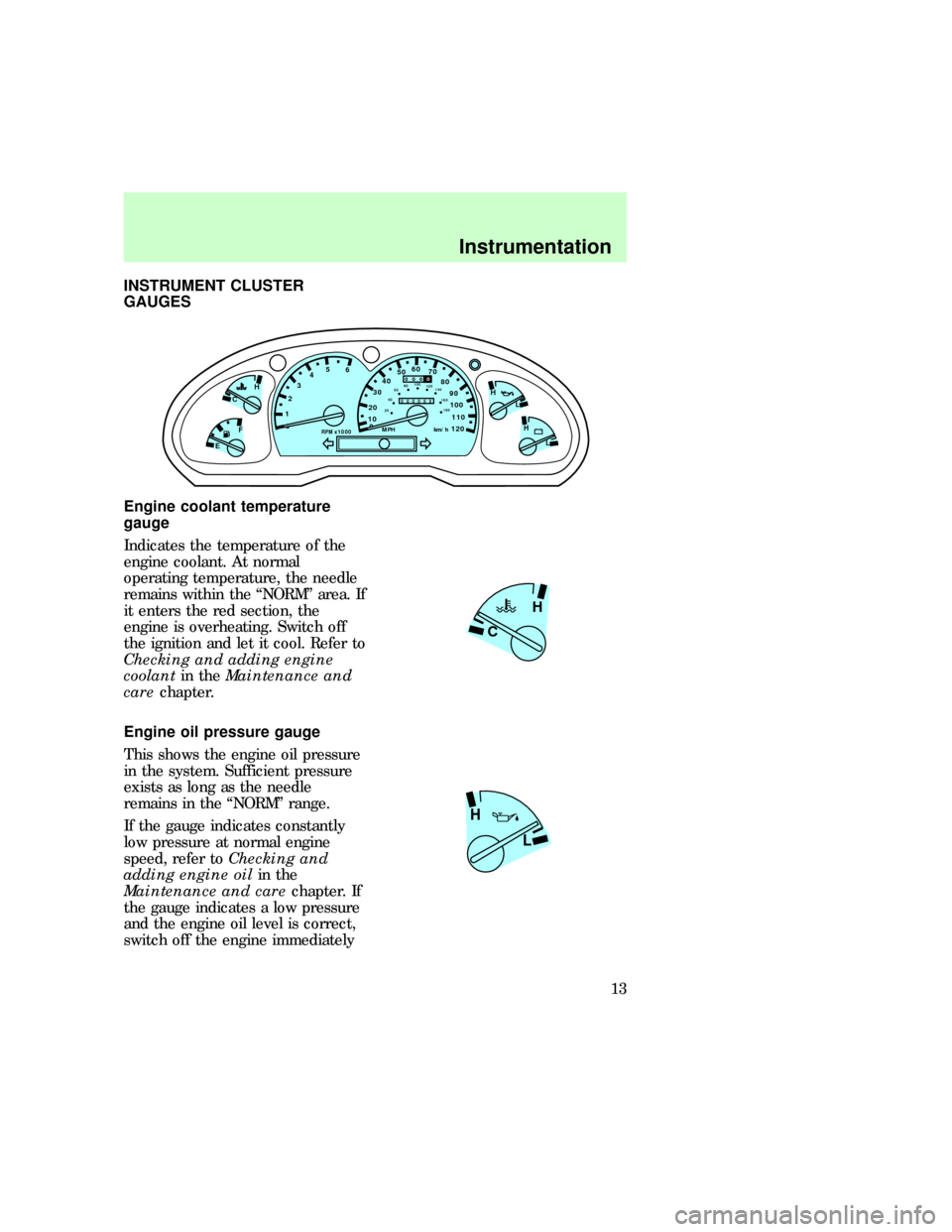
Engine coolant temperature
gauge
Indicates the temperature of the
engine coolant. At normal
operating temperature, the needle
remains within the ªNORMº area. If
it enters the red section, the
engine is overheating. Switch off
the ignition and let it cool. Refer to
Checking and adding engine
coolantin theMaintenance and
carechapter.
Engine oil pressure gauge
This shows the engine oil pressure
in the system. Sufficient pressure
exists as long as the needle
remains in the ªNORMº range.
If the gauge indicates constantly
low pressure at normal engine
speed, refer toChecking and
adding engine oilin the
Maintenance and carechapter. If
the gauge indicates a low pressure
and the engine oil level is correct,
switch off the engine immediately
0RPM x 1000
12345
6- +
H
H
L LH
C
F
E
0
20
1030405060
70
80
90
110
120000000
oooo
10020406080100
120
140
160
180
MPH km/h
H
C
H
L
com_coolant_temperature.01
com_oil_pressure.01
Instrumentation
13
Page 16 of 236
Fuel range
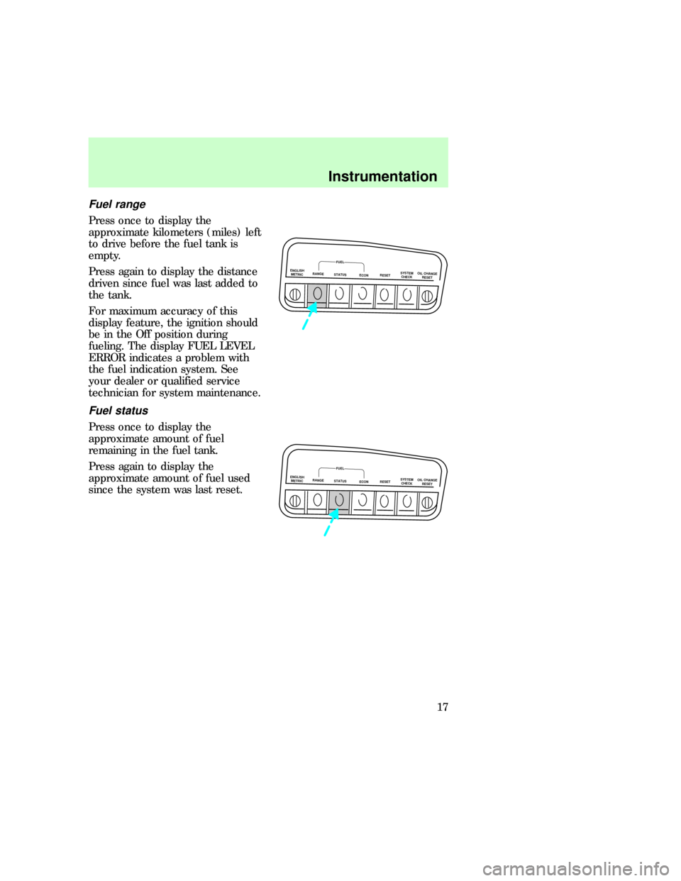
Press once to display the
approximate kilometers (miles) left
to drive before the fuel tank is
empty.
Press again to display the distance
driven since fuel was last added to
the tank.
For maximum accuracy of this
display feature, the ignition should
be in the Off position during
fueling. The display FUEL LEVEL
ERROR indicates a problem with
the fuel indication system. See
your dealer or qualified service
technician for system maintenance.
Fuel status
Press once to display the
approximate amount of fuel
remaining in the fuel tank.
Press again to display the
approximate amount of fuel used
since the system was last reset.
ENGLISH
METRICRANGESTATUS
ECONRESETSYSTEM
CHECKOIL CHANGE
RESET
FUEL
ENGLISH
METRICRANGESTATUS
ECONRESETSYSTEM
CHECKOIL CHANGE
RESET
FUEL
uno_fuel_status uno_fuel_economy
Instrumentation
17
Page 18 of 236

²automatic ride control (if
equipped)
²fuel level
The engine oil life left has two
phases. The first display will
indicate the oil change status (OK,
SOON, REQUIRED). The second
display will indicate the percentage
of oil life remaining. The display
OIL TEMP SIGNAL ERROR
indicates a problem with the
system. Following this display,
contact your dealer or qualified
service technician for system
maintenance.
Operating the message center
during system check
The message center controls will
operate as follows during the
system check sequence:
1. Press the system check controls
to advance to the next display.
2. Press the reset control to
immediately conclude the system
check.
3. Press the range, fuel status or
fuel economy control to conclude
the system check and display the
requested feature.
4. Press the metric/English control
to conclude the system check and
change the previous display to the
new mode.
5. Press the oil change reset
control to conclude the system
check and begin the oil change
reset procedure.
uno_operating_system
uno_oil_life_left
Instrumentation
19
Page 19 of 236
Engine oil life left
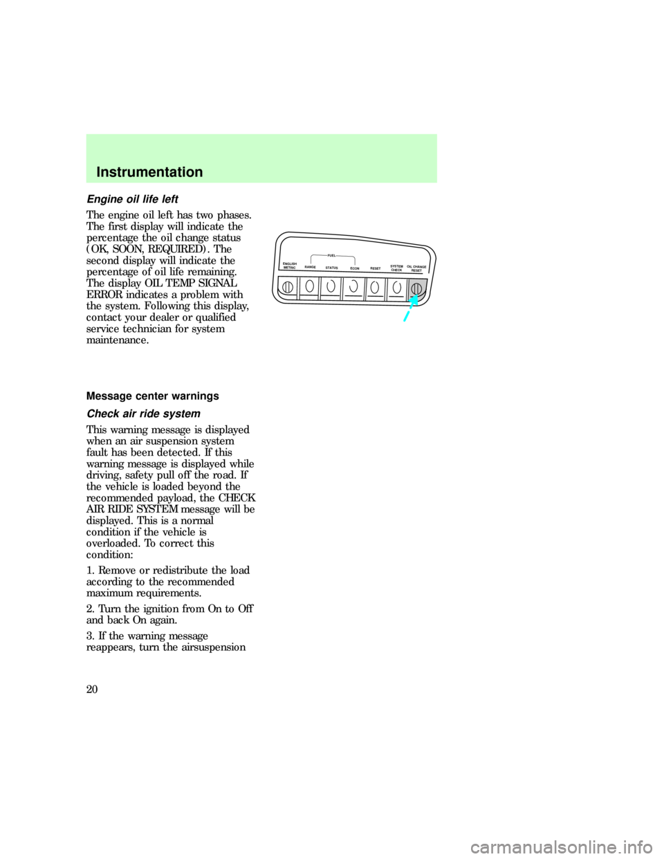
The engine oil left has two phases.
The first display will indicate the
percentage the oil change status
(OK, SOON, REQUIRED). The
second display will indicate the
percentage of oil life remaining.
The display OIL TEMP SIGNAL
ERROR indicates a problem with
the system. Following this display,
contact your dealer or qualified
service technician for system
maintenance.
Message center warnings
Check air ride system
This warning message is displayed
when an air suspension system
fault has been detected. If this
warning message is displayed while
driving, safety pull off the road. If
the vehicle is loaded beyond the
recommended payload, the CHECK
AIR RIDE SYSTEM message will be
displayed. This is a normal
condition if the vehicle is
overloaded. To correct this
condition:
1. Remove or redistribute the load
according to the recommended
maximum requirements.
2. Turn the ignition from On to Off
and back On again.
3. If the warning message
reappears, turn the airsuspension
ENGLISH
METRICRANGESTATUS
ECONRESETSYSTEM
CHECKOIL CHANGE
RESET
FUEL
uno_warnings_title
uno_check_air_ride
Instrumentation
20
Page 23 of 236
get a false warning or no warning
at all.
Door ajar
The ignition switch is in the On or
Start position and a door is open.
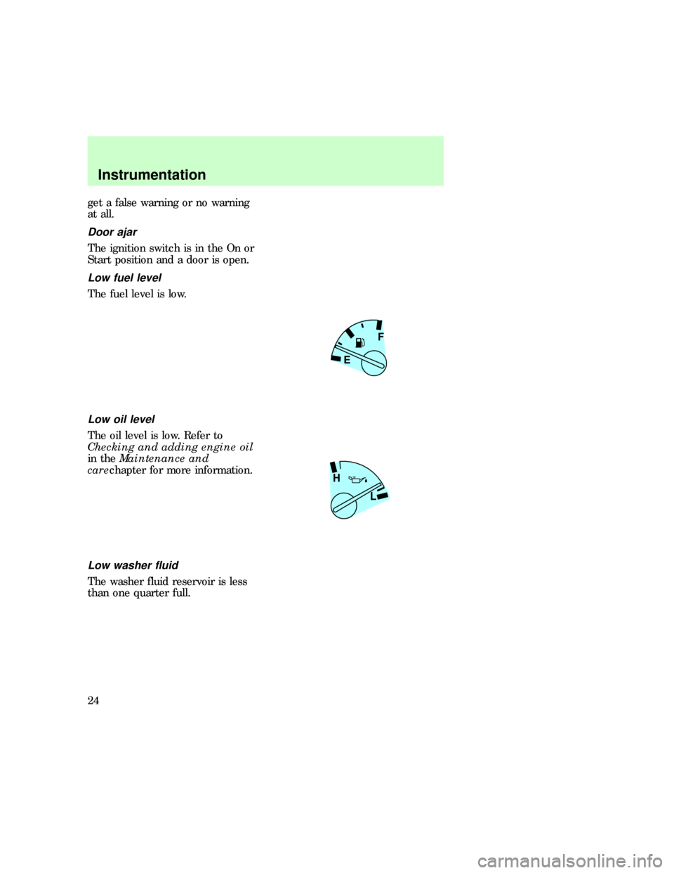
Low fuel level
The fuel level is low.
Low oil level
The oil level is low. Refer to
Checking and adding engine oil
in theMaintenance and
carechapter for more information.
Low washer fluid
The washer fluid reservoir is less
than one quarter full.
F
E
H
L
uno_door_ajar
uno_low_fuel uno_low_oil
uno_low_washer
Instrumentation
24
Page 92 of 236

The diagnostic module monitors its
own internal circuits and the
supplemental air bag electrical
system readiness (including the
impact sensors), the system wiring,
the air bag system readiness light,
the air bag back up power and the
air bag ignitors.
Determining if the system is
operational
The SRS uses a readiness light in
the instrument cluster or a tone to
indicate the condition of the
system. Refer to theAir bag
readinesssection in the
Instrumentationchapter. Routine
maintenance of the air bag is not
required.
A difficulty with the system is
indicated by one or more of the
following:
²The readiness light will either
flash or stay lit.
²The readiness light will not
illuminate immediately after
ignition is turned on.
²A group of five beeps will be
heard. The tone pattern will
repeat periodically until the
problem and light are repaired.
If any of these things happen, even
intermittently, have the SRS
serviced at your dealership or by a
qualified technician immediately.
Unless serviced, the system may
not function properly in the event
of a collision.
uno_determing_operational
com_disposal.01
Seating and safety restraints
93
Page 116 of 236
BRAKES
Your brakes are self-adjusting.
Refer to the ªService Guideº for
maintenance scheduling.
Anti-lock brake system (ABS)
(if equipped)
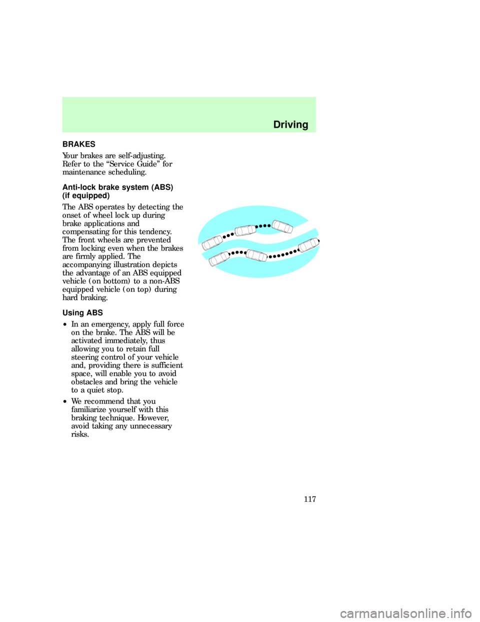
The ABS operates by detecting the
onset of wheel lock up during
brake applications and
compensating for this tendency.
The front wheels are prevented
from locking even when the brakes
are firmly applied. The
accompanying illustration depicts
the advantage of an ABS equipped
vehicle (on bottom) to a non-ABS
equipped vehicle (on top) during
hard braking.
Using ABS
²In an emergency, apply full force
on the brake. The ABS will be
activated immediately, thus
allowing you to retain full
steering control of your vehicle
and, providing there is sufficient
space, will enable you to avoid
obstacles and bring the vehicle
to a quiet stop.
²We recommend that you
familiarize yourself with this
braking technique. However,
avoid taking any unnecessary
risks.com_brakes.01
com_abs.01
com_using_abs.01
uno_parking_brake
Driving
117
Page 144 of 236

Your vehicle can not be flat towed
with all wheels on the ground.
Servicing while towing
If you tow a trailer for long
distances, your vehicle requires
more frequent service than a
vehicle not used for towing. Refer
to the ªService Guideº for more
information on maintenance
intervals.
Using a step bumper
The rear bumper is equipped with
an integral hitch and requires only
a ball with a ô inch shank
diameter. The bumper has a Class
II capability (1590 kg / 3500 lb
trailer weight and 159 kg / 350 lb
tongue weight).
Use a frame mounted weight
distributing hitch for trailers over
1590 kg (3500 lb).
Launching or retrieving a boat
When backing down a ramp during
boat launching or retrieval,
²Do not allow the static water
level to rise above the bottom
edge of the rear bumper and
²Do not allow waves to break
higher than 15 cm (six inches)
above the bottom edge of the
rear bumper.
Exceeding these limits may allow
water to enter critical vehicle
components, adversely affecting
driveability, emissions and
reliability.uno_servicing_while_towing
uno_step_bumper_towing
com_launch-retrieving_boat.01
uno_roof-rack_title
Driving
145
Page 145 of 236
USING THE LUGGAGE RACK
(IF EQUIPPED)
Maximum load is 100 lbs, evenly
distributed. If it is not possible to
distribute the load, position it as
far rearward as possible.
Adjustable tie down loops must be
used to secure the load.
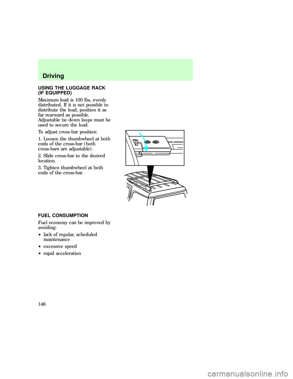
To adjust cross-bar position:
1. Loosen the thumbwheel at both
ends of the cross-bar (both
cross-bars are adjustable).
2. Slide cross-bar to the desired
location.
3. Tighten thumbwheel at both
ends of the cross-bar.
FUEL CONSUMPTION
Fuel economy can be improved by
avoiding:
²lack of regular, scheduled
maintenance
²excessive speed
²rapid acceleration
com_fuel_consumption.01
Driving
146