technical FORD EXPLORER 2014 5.G Owners Manual
[x] Cancel search | Manufacturer: FORD, Model Year: 2014, Model line: EXPLORER, Model: FORD EXPLORER 2014 5.GPages: 586, PDF Size: 9.07 MB
Page 8 of 586
Vehicle Care 343
Cleaning products.....................................343
Cleaning the exterior..................................343
Waxing.............................................345
Repairing minor paint damage............................345
Cleaning the engine...................................345
Cleaning the windows and wiper blades.....................346
Cleaning the interior...................................347
Cleaning the instrument panel and instrument cluster lens.......347
Cleaning leather seats..................................348
Cleaning the alloy wheels...............................349
Vehiclestorage.......................................349
Wheels and Tires 352
Tire care...........................................354
Using snow chains....................................370
Tire Pressure Monitoring System (TPMS)...................371
Changing a road wheel.................................376
Technical specifications.................................384
Wheel lug nut torque..................................384
Capacities and Specifications 385
Engine specifications..................................385
Part numbers........................................391
Vehicle identification number............................391
Vehicle certification label...............................392
Transmission code designation............................393
Accessories 394
Accessories.........................................394
Table of Contents7
2014 Explorer(exp)
Owners Guide gf, 1st Printing, April 2013
USA(fus)
Page 57 of 586
WARNING:Do not attempt to service, repair, or modify the
airbag, its fuses or the seat cover on a seat containing an airbag,
as you could be seriously injured or killed. Contact your authorized
dealer as soon as possible.
WARNING:If the side airbag has deployed, the airbag will not
function again. The side airbag system (including the seat) must
be inspected and serviced by an authorized dealer. If the airbag is not
replaced, the unrepaired area will increase the risk of injury in a crash.
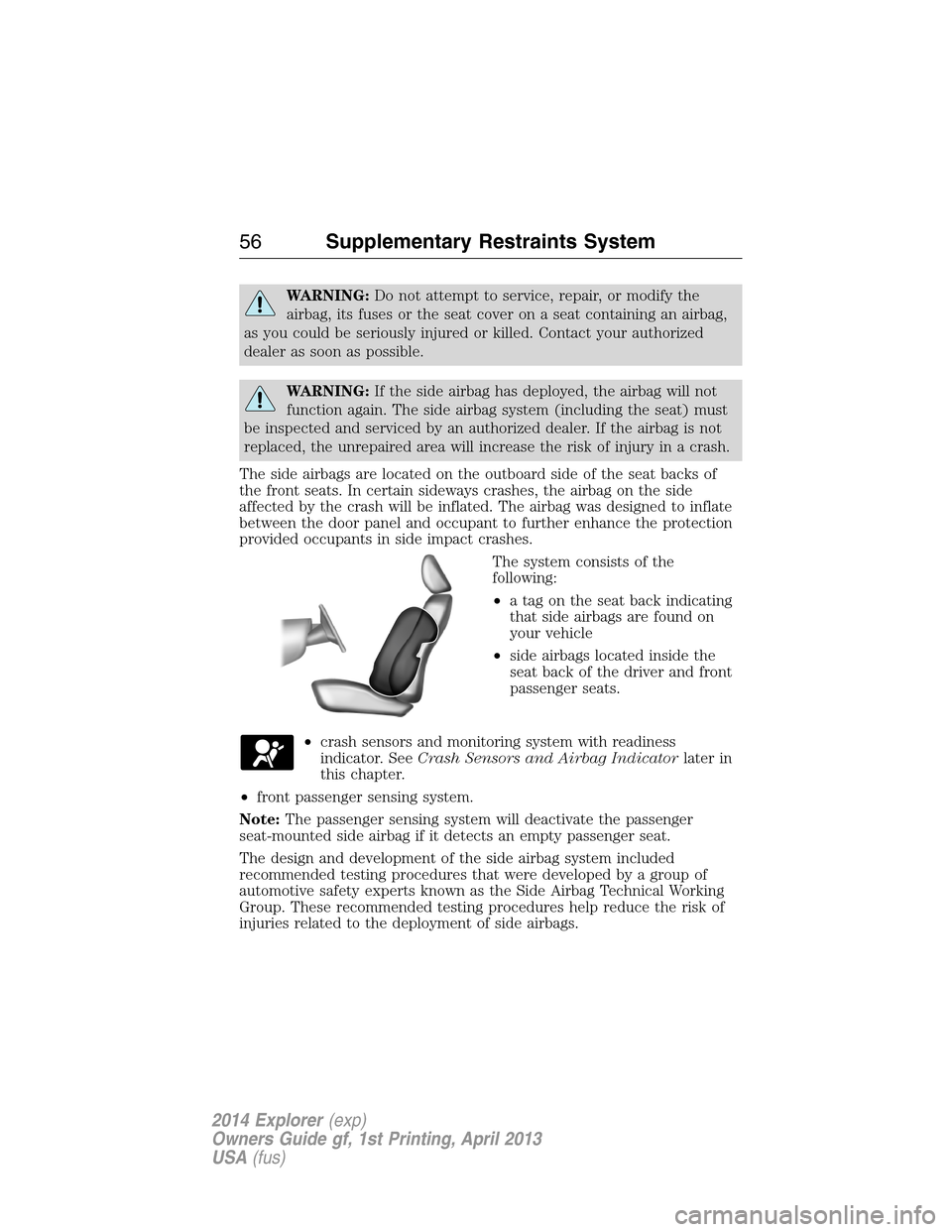
The side airbags are located on the outboard side of the seat backs of
the front seats. In certain sideways crashes, the airbag on the side
affected by the crash will be inflated. The airbag was designed to inflate
between the door panel and occupant to further enhance the protection
provided occupants in side impact crashes.
The system consists of the
following:
•a tag on the seat back indicating
that side airbags are found on
your vehicle
•side airbags located inside the
seat back of the driver and front
passenger seats.
•crash sensors and monitoring system with readiness
indicator. SeeCrash Sensors and Airbag Indicatorlater in
this chapter.
•front passenger sensing system.
Note:The passenger sensing system will deactivate the passenger
seat-mounted side airbag if it detects an empty passenger seat.
The design and development of the side airbag system included
recommended testing procedures that were developed by a group of
automotive safety experts known as the Side Airbag Technical Working
Group. These recommended testing procedures help reduce the risk of
injuries related to the deployment of side airbags.
56Supplementary Restraints System
2014 Explorer(exp)
Owners Guide gf, 1st Printing, April 2013
USA(fus)
Page 59 of 586
The Safety Canopy will deploy during significant side crashes or when a
certain likelihood of a rollover event is detected by the rollover sensor.
The Safety Canopy is mounted to the roof side-rail sheet metal, behind
the headliner, above each row of seats. In certain sideways crashes or
rollover events, the Safety Canopy will be activated, regardless of which
seats are occupied. The Safety Canopy is designed to inflate between the
side window area and occupants to further enhance protection provided
in side impact crashes and rollover events.
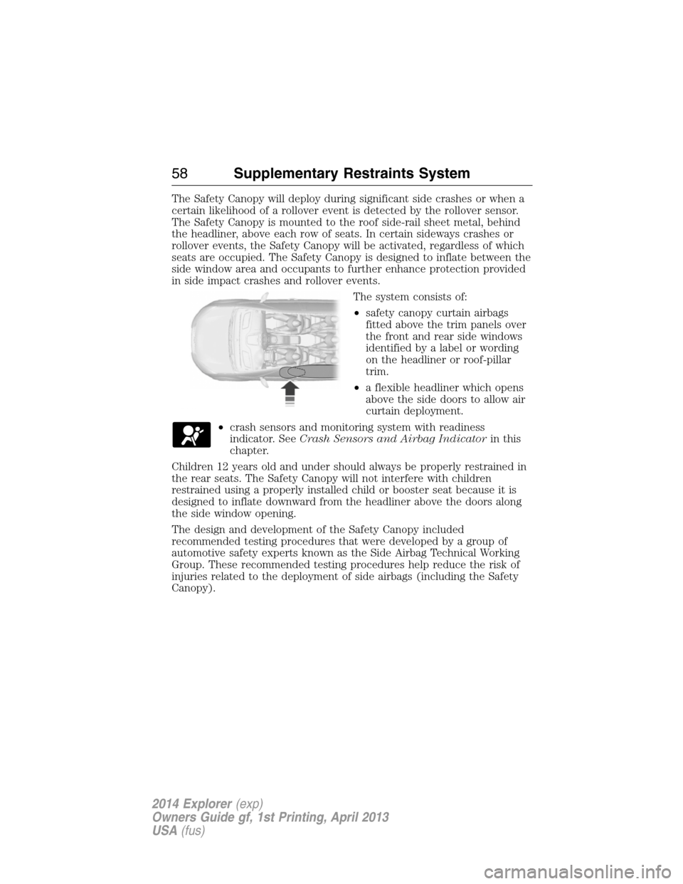
The system consists of:
•safety canopy curtain airbags
fitted above the trim panels over
the front and rear side windows
identified by a label or wording
on the headliner or roof-pillar
trim.
•a flexible headliner which opens
above the side doors to allow air
curtain deployment.
•crash sensors and monitoring system with readiness
indicator. SeeCrash Sensors and Airbag Indicatorin this
chapter.
Children 12 years old and under should always be properly restrained in
the rear seats. The Safety Canopy will not interfere with children
restrained using a properly installed child or booster seat because it is
designed to inflate downward from the headliner above the doors along
the side window opening.
The design and development of the Safety Canopy included
recommended testing procedures that were developed by a group of
automotive safety experts known as the Side Airbag Technical Working
Group. These recommended testing procedures help reduce the risk of
injuries related to the deployment of side airbags (including the Safety
Canopy).
58Supplementary Restraints System
2014 Explorer(exp)
Owners Guide gf, 1st Printing, April 2013
USA(fus)
Page 62 of 586
GENERAL INFORMATION ON RADIO FREQUENCIES
This device complies with part 15 of the FCC Rules and with Industry
Canada license-exempt RSS standard(s). Operation is subject to the
following two conditions: (1) This device may not cause harmful
interference, and (2) This device must accept any interference received,
including interference that may cause undesired operation.
Note:Changes or modifications not expressly approved by the party
responsible for compliance could void the user’s authority to operate the
equipment. The termICbefore the radio certification number only
signifies that Industry Canada technical specifications were met.
The typical operating range for your transmitter is approximately 33 feet
(10 meters). Vehicles with the remote start feature will have a greater
range. A decrease in operating range could be caused by:
•weather conditions
•nearby radio towers
•structures around your vehicle
•other vehicles parked next to your vehicle.
The radio frequency used by your remote control can also be used by
other short-distance radio transmissions, for example amateur radios,
medical equipment, wireless headphones, remote controls and alarm
systems. If the frequencies are jammed, you will not be able to use your
remote control. You can lock and unlock the doors with the key.
Note:Make sure your vehicle is locked before leaving it unattended.
Note:If you are in range, the remote control will operate if you press
any button unintentionally.
Intelligent Access (If Equipped)
The system uses a radio frequency signal to communicate with your
vehicle and authorize your vehicle to unlock when one of the following
conditions is met:
•You touch the inside of the front exterior door handle.
•You press the luggage compartment button.
•You press a button on the transmitter.
If excessive radio frequency interference is present in the area or if the
transmitter battery is low, it may be necessary to mechanically unlock
your door. You can use the mechanical key blade in your intelligent
access key to open the driver door in this situation. Refer toRemote
Controlin this chapter for more information on the location and use of
the mechanical key blade.
Keys and Remote Control61
2014 Explorer(exp)
Owners Guide gf, 1st Printing, April 2013
USA(fus)
Page 328 of 586
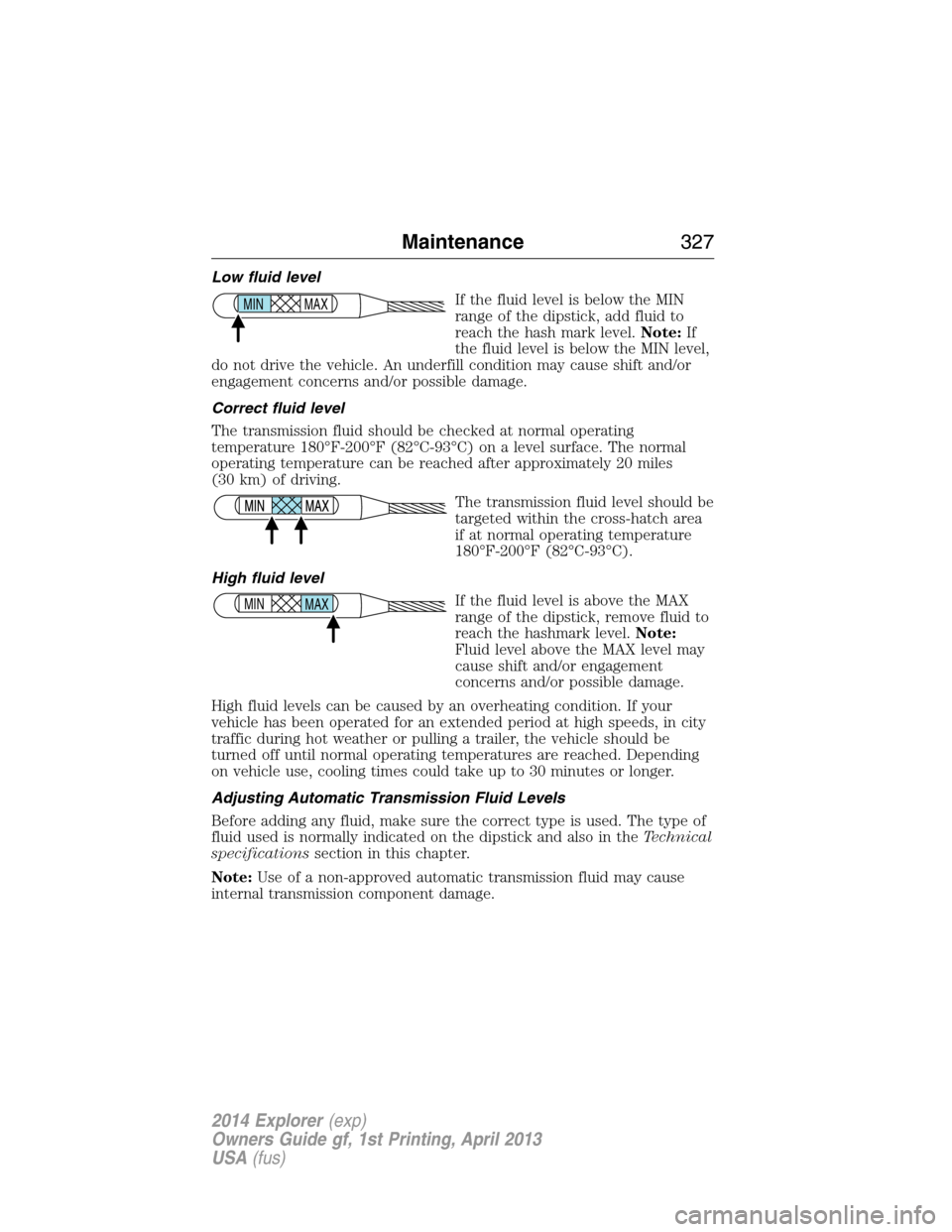
Low fluid level
If the fluid level is below the MIN
range of the dipstick, add fluid to
reach the hash mark level.Note:If
the fluid level is below the MIN level,
do not drive the vehicle. An underfill condition may cause shift and/or
engagement concerns and/or possible damage.
Correct fluid level
The transmission fluid should be checked at normal operating
temperature 180°F-200°F (82°C-93°C) on a level surface. The normal
operating temperature can be reached after approximately 20 miles
(30 km) of driving.
The transmission fluid level should be
targeted within the cross-hatch area
if at normal operating temperature
180°F-200°F (82°C-93°C).
High fluid level
If the fluid level is above the MAX
range of the dipstick, remove fluid to
reach the hashmark level.Note:
Fluid level above the MAX level may
cause shift and/or engagement
concerns and/or possible damage.
High fluid levels can be caused by an overheating condition. If your
vehicle has been operated for an extended period at high speeds, in city
traffic during hot weather or pulling a trailer, the vehicle should be
turned off until normal operating temperatures are reached. Depending
on vehicle use, cooling times could take up to 30 minutes or longer.
Adjusting Automatic Transmission Fluid Levels
Before adding any fluid, make sure the correct type is used. The type of
fluid used is normally indicated on the dipstick and also in theTechnical
specificationssection in this chapter.
Note:Use of a non-approved automatic transmission fluid may cause
internal transmission component damage.
MAX MIN
MAX MIN
Maintenance327
2014 Explorer(exp)
Owners Guide gf, 1st Printing, April 2013
USA(fus)
Page 330 of 586
FUEL FILTER
Your vehicle is equipped with a lifetime fuel filter that is integrated with
the fuel tank. Regular maintenance or replacement is not needed.
WASHER FLUID CHECK
WARNING:If you operate your vehicle in temperatures below
40°F (5°C), use washer fluid with antifreeze protection. Failure
to use washer fluid with antifreeze protection in cold weather could
result in impaired windshield vision and increase the risk of injury or
accident.
Add fluid to fill the reservoir if the level is low. Only use a washer fluid
that meets Ford specifications. See the technical specifications chart in
theCapacities and Specificationschapter.
Note:The front and rear washer systems are supplied from the same
reservoir.
State or local regulations on volatile organic compounds may restrict the
use of methanol, a common windshield washer antifreeze additive.
Washer fluids containing non-methanol antifreeze agents should be used
only if they provide cold weather protection without damaging the
vehicle’s paint finish, wiper blades or washer system.
CHANGING THE VEHICLE BATTERY
WARNING:Batteries normally produce explosive gases which
can cause personal injury. Therefore, do not allow flames, sparks
or lighted substances to come near the battery. When working near the
battery, always shield your face and protect your eyes. Always provide
proper ventilation.
WARNING:When lifting a plastic-cased battery, excessive
pressure on the end walls could cause acid to flow through the
vent caps, resulting in personal injury and damage to the vehicle or
battery. Lift the battery with a battery carrier or with your hands on
opposite corners.
Maintenance329
2014 Explorer(exp)
Owners Guide gf, 1st Printing, April 2013
USA(fus)
Page 359 of 586
•Sidewall of the tire:Area between the bead area and the tread.
•Tread area of the tire:Area of the perimeter of the tire that
contacts the road when mounted on the vehicle.
•Rim:The metal support (wheel) for a tire or a tire and tube assembly
upon which the tire beads are seated.
INFORMATION CONTAINED ON THE TIRE SIDEWALL
Both U.S. and Canada Federal regulations require tire manufacturers to
place standardized information on the sidewall of all tires. This
information identifies and describes the fundamental characteristics of
the tire and also provides a U.S. DOT Tire Identification Number for
safety standard certification and in case of a recall.
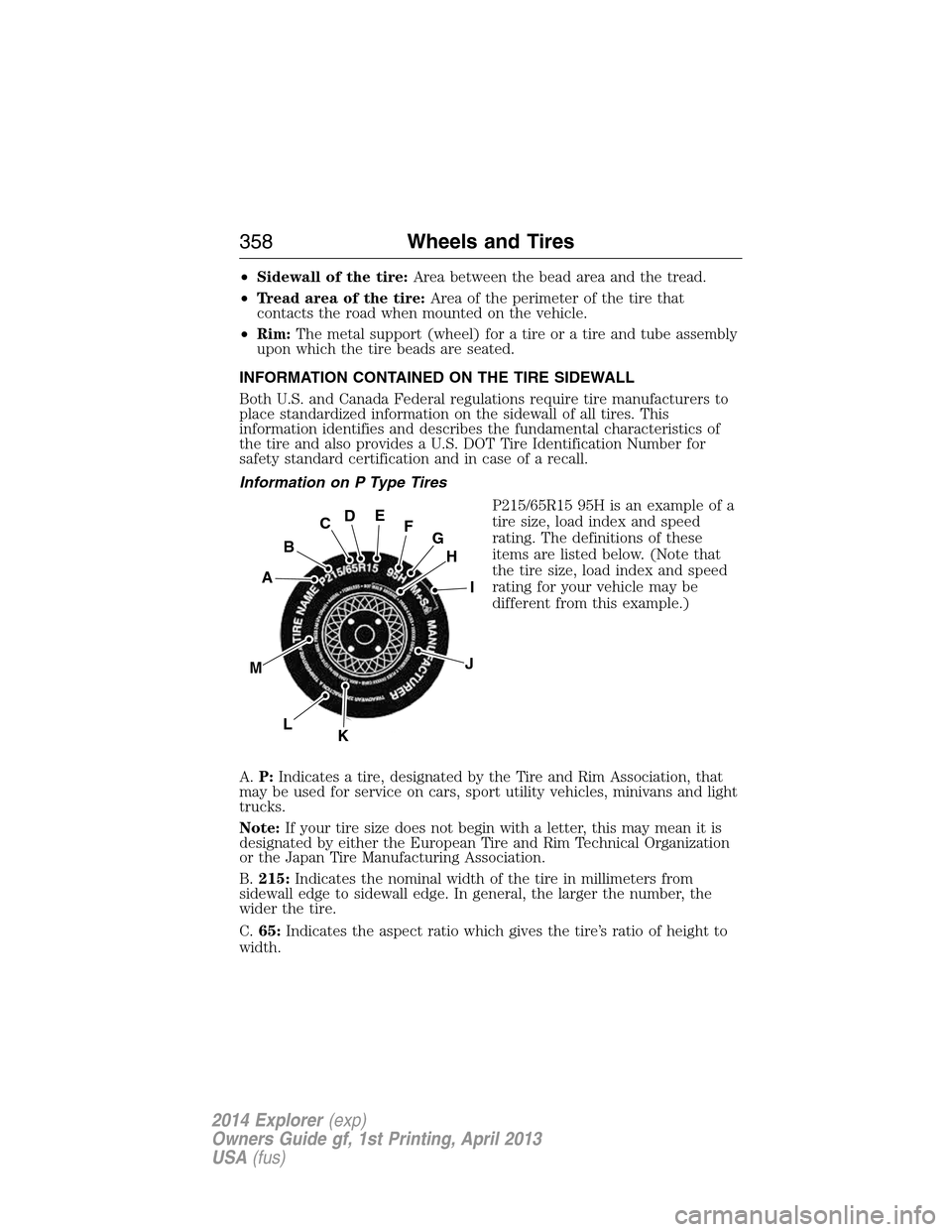
Information on P Type Tires
P215/65R15 95H is an example of a
tire size, load index and speed
rating. The definitions of these
items are listed below. (Note that
the tire size, load index and speed
rating for your vehicle may be
different from this example.)
A.P:Indicates a tire, designated by the Tire and Rim Association, that
may be used for service on cars, sport utility vehicles, minivans and light
trucks.
Note:If your tire size does not begin with a letter, this may mean it is
designated by either the European Tire and Rim Technical Organization
or the Japan Tire Manufacturing Association.
B.215:Indicates the nominal width of the tire in millimeters from
sidewall edge to sidewall edge. In general, the larger the number, the
wider the tire.
C.65:Indicates the aspect ratio which gives the tire’s ratio of height to
width.
H
I
J
KL
M
A
B
CDEFG
358Wheels and Tires
2014 Explorer(exp)
Owners Guide gf, 1st Printing, April 2013
USA(fus)
Page 385 of 586
TECHNICAL SPECIFICATIONS
Wheel Lug Nut Torque Specifications
WARNING:When a wheel is installed, always remove any
corrosion, dirt or foreign materials present on the mounting
surfaces of the wheel or the surface of the wheel hub, brake drum or
brake disc that contacts the wheel. Make sure that any fasteners that
attach the rotor to the hub are secured so they do not interfere with
the mounting surfaces of the wheel. Installing wheels without correct
metal-to-metal contact at the wheel mounting surfaces can cause the
wheel nuts to loosen and the wheel to come off while your vehicle is in
motion, resulting in loss of control.
Retighten the lug nuts to the specified torque within 100 miles
(160 kilometers) after any wheel disturbance (such as rotation, flat tire,
wheel removal).
Lug nut socket
size/Bolt sizeWheel lug nut torque*
ft-lb N•m
12x 20 100 135
* Torque specifications are for nut and bolt threads free of dirt and
rust. Use only Ford recommended replacement fasteners.
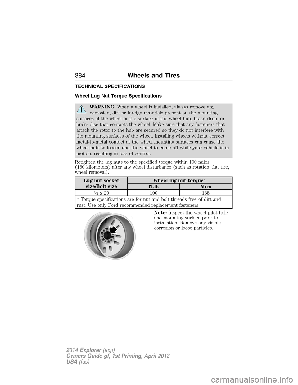
Note:Inspect the wheel pilot hole
and mounting surface prior to
installation. Remove any visible
corrosion or loose particles.
384Wheels and Tires
2014 Explorer(exp)
Owners Guide gf, 1st Printing, April 2013
USA(fus)
Page 388 of 586
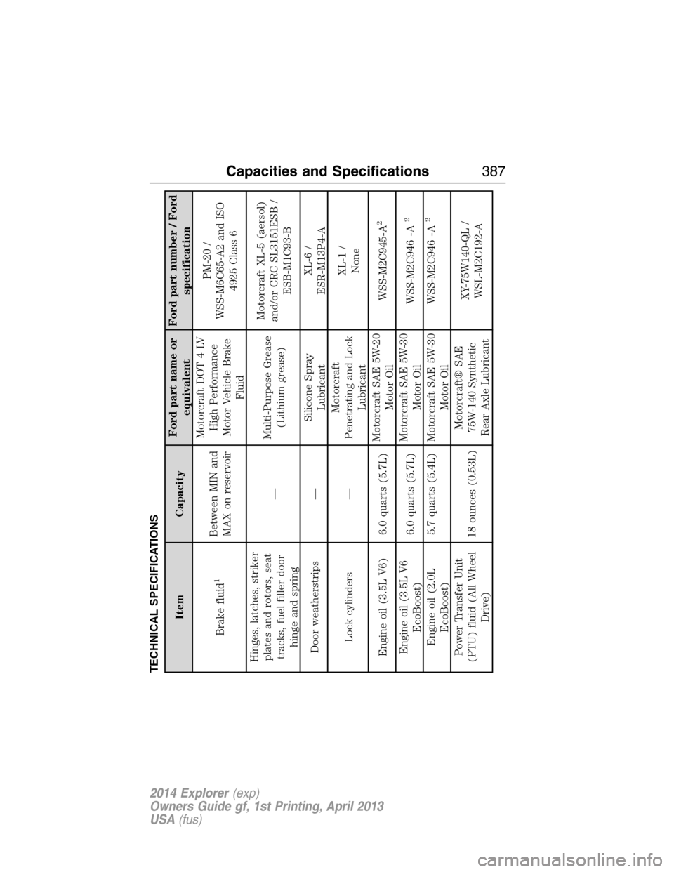
TECHNICAL SPECIFICATIONS
Item CapacityFord part name or
equivalentFord part number / Ford
specification
Brake fluid
1
Between MIN and
MAX on reservoirMotorcraft DOT 4 LV
High Performance
Motor Vehicle Brake
FluidPM-20 /
WSS-M6C65-A2 and ISO
4925 Class 6
Hinges, latches, striker
plates and rotors, seat
tracks, fuel filler door
hinge and spring—Multi-Purpose Grease
(Lithium grease)Motorcraft XL-5 (aersol)
and/or CRC SL3151ESB /
ESB-M1C93-B
Door weatherstrips —Silicone Spray
LubricantXL-6 /
ESR-M13P4-A
Lock cylinders —Motorcraft
Penetrating and Lock
LubricantXL-1 /
None
Engine oil (3.5L V6) 6.0 quarts (5.7L)Motorcraft SAE 5W-20
Motor OilWSS-M2C945-A
2
Engine oil (3.5L V6
EcoBoost)6.0 quarts (5.7L)Motorcraft SAE 5W-30
Motor OilWSS-M2C946 -A
2
Engine oil (2.0L
EcoBoost)5.7 quarts (5.4L) Motorcraft SAE 5W-30
Motor OilWSS-M2C946 -A
2
Power Transfer Unit
(PTU) fluid (All Wheel
Drive)18 ounces (0.53L)Motorcraft® SAE
75W-140 Synthetic
Rear Axle LubricantXY-75W140-QL /
WSL-M2C192-A
Capacities and Specifications387
2014 Explorer(exp)
Owners Guide gf, 1st Printing, April 2013
USA(fus)
Page 401 of 586
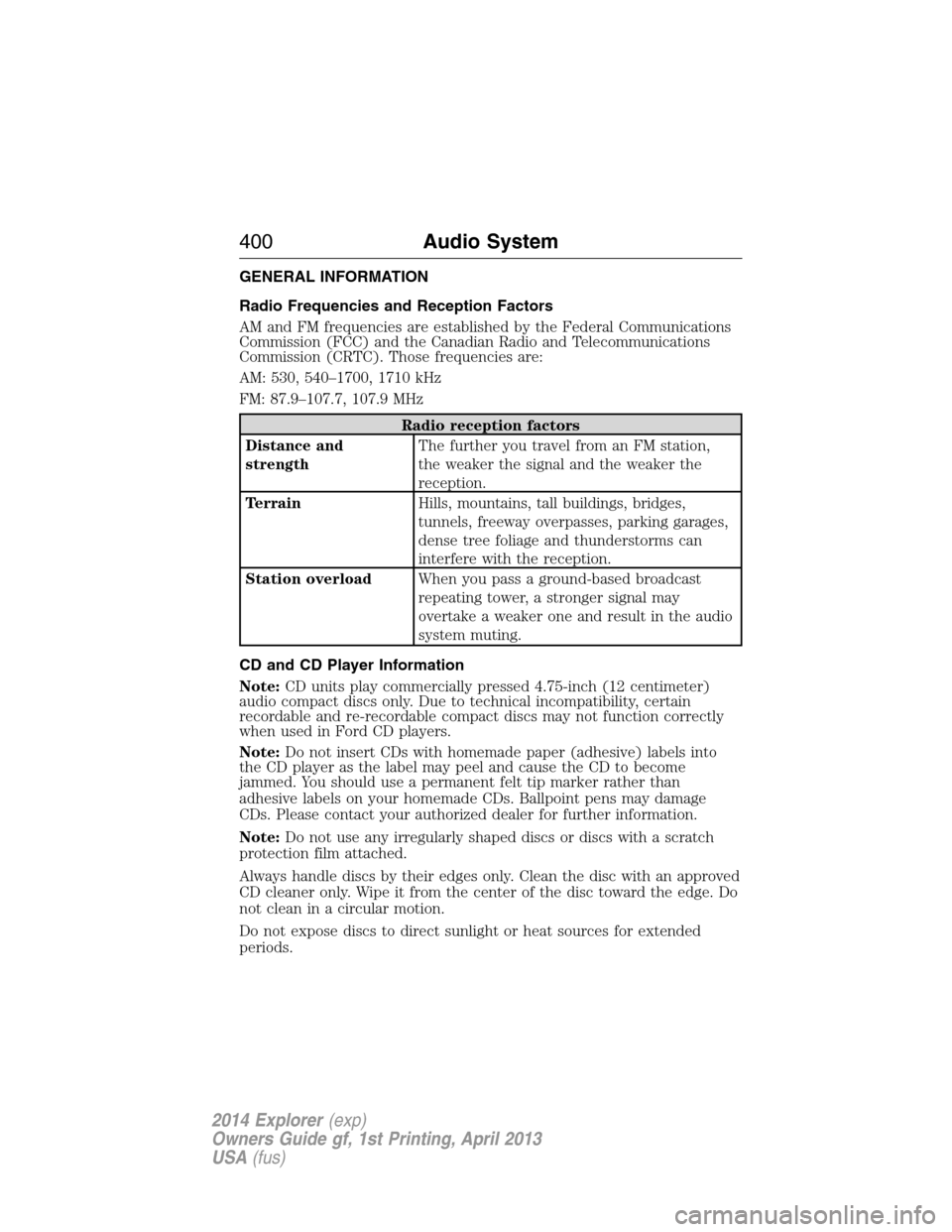
GENERAL INFORMATION
Radio Frequencies and Reception Factors
AM and FM frequencies are established by the Federal Communications
Commission (FCC) and the Canadian Radio and Telecommunications
Commission (CRTC). Those frequencies are:
AM: 530, 540–1700, 1710 kHz
FM: 87.9–107.7, 107.9 MHz
Radio reception factors
Distance and
strengthThe further you travel from an FM station,
the weaker the signal and the weaker the
reception.
TerrainHills, mountains, tall buildings, bridges,
tunnels, freeway overpasses, parking garages,
dense tree foliage and thunderstorms can
interfere with the reception.
Station overloadWhen you pass a ground-based broadcast
repeating tower, a stronger signal may
overtake a weaker one and result in the audio
system muting.
CD and CD Player Information
Note:CD units play commercially pressed 4.75-inch (12 centimeter)
audio compact discs only. Due to technical incompatibility, certain
recordable and re-recordable compact discs may not function correctly
when used in Ford CD players.
Note:Do not insert CDs with homemade paper (adhesive) labels into
the CD player as the label may peel and cause the CD to become
jammed. You should use a permanent felt tip marker rather than
adhesive labels on your homemade CDs. Ballpoint pens may damage
CDs. Please contact your authorized dealer for further information.
Note:Do not use any irregularly shaped discs or discs with a scratch
protection film attached.
Always handle discs by their edges only. Clean the disc with an approved
CD cleaner only. Wipe it from the center of the disc toward the edge. Do
not clean in a circular motion.
Do not expose discs to direct sunlight or heat sources for extended
periods.
400Audio System
2014 Explorer(exp)
Owners Guide gf, 1st Printing, April 2013
USA(fus)