tow spec FORD EXPLORER 2021 Owners Manual
[x] Cancel search | Manufacturer: FORD, Model Year: 2021, Model line: EXPLORER, Model: FORD EXPLORER 2021Pages: 577, PDF Size: 9.79 MB
Page 9 of 577
Essential Towing Checks
.........................292
Towing the Vehicle on Four Wheels .....
294
Driving Hints
Reduced Engine Performance ...............
295
Economical Driving ....................................
295
Cold Weather Precautions ......................
296
Breaking-In ...................................................
296
Driving Through Water .............................
296
Floor Mats ......................................................
297
Roadside Emergencies
Roadside Assistance .................................
298
Hazard Flashers ..........................................
299
Fuel Shutoff .................................................
299
Jump Starting the Vehicle ......................
300
Collision, Damage or Fire Event ............
302
Post-Crash Alert System .........................
303
Transporting the Vehicle .........................
303
Customer Assistance
Getting the Services You Need .............
305
In California (U.S. Only) ...........................
306
The Better Business Bureau (BBB) Auto Line Program (U.S. Only) .....................
307
Utilizing the Mediation/Arbitration Program (Canada Only) .....................
308
Getting Assistance Outside the U.S. and Canada ......................................................
308
Ordering Additional Owner's Literature ........................................................................\
.
310
Reporting Safety Defects (U.S. Only) ........................................................................\
.
310
Reporting Safety Defects (Canada Only) ........................................................................\
.
310
Fuses
Fuse Specification Chart ...........................
312
Changing a Fuse .........................................
320Maintenance
General Information
...................................
322
Opening and Closing the Hood .............
322
Under Hood Overview - 2.3L EcoBoost™ ........................................................................\
323
Under Hood Overview - 3.0L ..................
324
Under Hood Overview - 3.3L ..................
325
Engine Oil Dipstick - 2.3L EcoBoost™ ........................................................................\
326
Engine Oil Dipstick - 3.0L ........................
326
Engine Oil Dipstick - 3.3L .........................
326
Engine Oil Check .........................................
326
Oil Change Indicator Reset ......................
327
Changing the Engine Air Filter - 2.3L EcoBoost™ ...............................................
328
Changing the Engine Air Filter - 3.0L ........................................................................\
329
Changing the Engine Air Filter - 3.3L ....
330
Engine Coolant Check ................................
331
Automatic Transmission Fluid Check ........................................................................\
335
Brake Fluid Check .......................................
335
Power Steering Fluid Check ....................
336
Changing the 12V Battery ........................
336
Adjusting the Headlamps .......................
338
Washer Fluid Check ...................................
340
Fuel Filter .......................................................
340
Checking the Wiper Blades ....................
340
Changing the Front Wiper Blades ........
340
Changing the Rear Wiper Blades ...........
341
Changing a Bulb ...........................................
341
Vehicle Care
General Information ..................................
343
Cleaning Products ......................................
343
Cleaning the Exterior .................................
344
Waxing ............................................................
345
Cleaning the Engine ...................................
345
Cleaning the Windows and Wiper Blades ........................................................................\
346
6
Explorer (CTW), enUSA, Edition date: 202007, Second-Printing Table of Contents
Page 20 of 577
Note:
Event data recorder data is recorded
by your vehicle only if a non-trivial crash
situation occurs; no data is recorded by the
event data recorder under normal driving
conditions and no personal data or
information (for example name, gender,
age, and crash location) is recorded.
However, parties, such as law enforcement,
could combine the event data recorder data
with the type of personally identifying data
routinely acquired during a crash
investigation.
To read data recorded by an event data
recorder, special equipment is required,
and access to the vehicle or the event data
recorder is needed. In addition to the
vehicle manufacturer, other parties, such
as law enforcement, that have such special
equipment, can read the information if they
have access to the vehicle or the event
data recorder.
SETTINGS DATA
Your vehicle has electronic control units
that have the ability to store data based
on your personalized settings. The data is
stored locally in the vehicle or on devices
that you connect to it, for example, a USB
drive or digital music player. You can delete
some of this data and also choose whether
to share it through the services to which
you subscribe. See Settings (page 464).
Comfort and Convenience Data
Data recorded includes, for example:
• Seat and steering wheel position.
• Climate control settings.
• Radio presets. Entertainment Data
Data recorded includes, for example:
•
Music, videos or album art.
• Contacts and corresponding address
book entries.
• Navigation destinations.
CONNECTED VEHICLE DATA The modem has a SIM. The
modem was enabled when your
vehicle was built and periodically
sends messages to stay connected to the
cell phone network, receive automatic
software updates and send vehicle-related
information to us, for example diagnostic
information. These messages could
include information that identifies your
vehicle, the SIM and the electronic serial
number of the modem. Cell phone network
service providers could have access to
additional information, for example cell
phone network tower identification. For
additional information about our privacy
policy, visit
www .For dC onne c t e d . c om or
refer to your local Ford website.
Note: The modem continues to send this
information unless you disable the modem
or stop the modem from sharing vehicle
data by changing the modem settings.
See
Connected Vehicle (page 421).
Note: The service can be unavailable or
interrupted for a number of reasons, for
example environmental or topographical
conditions and data plan coverage.
Note: To find out if your vehicle has a
modem, visit
www .For dC onne c t e d . c om .
17
Explorer (CTW), enUSA, Edition date: 202007, Second-Printing Data Privacy
Page 43 of 577
Pregnant women should always wear their
seatbelt. Position the lap belt portion of a
combination lap and shoulder belt low
across the hips below the belly and worn
as tight as comfort allows. Position the
shoulder belt to cross the middle of the
shoulder and the center of the chest.
Seatbelt Locking Modes
WARNING: If your vehicle is
involved in a crash, have the seatbelts
and associated components inspected
as soon as possible. Failure to follow this
instruction could result in personal injury
or death.
All safety restraints in the vehicle are
combination lap and shoulder belts. The
driver seatbelt has the first type of locking
mode, and the front outboard passenger
and rear seat seatbelts have both types of
locking modes described as follows:
Vehicle Sensitive Mode
This is the normal retractor mode, which
allows free shoulder belt length
adjustment to your movements and
locking in response to vehicle movement.
For example, if the driver brakes suddenly
or turns a corner sharply, or the vehicle
receives an impact of about
5 mph
(8 km/h) or more, the combination
seatbelts lock to help reduce forward
movement of the driver and passengers.
In addition, the design of the retractor is to
lock if you pull the webbing out too quickly.
If the seatbelt retractor locks, slowly lower
the height adjuster to allow the seatbelt
to retract. If the retractor does not unlock,
pull the seatbelt out slowly then feed a small length of webbing back toward the
stowed position. For rear seatbelts, recline
the rear seat backrest or push the seat
backrest cushion away from the seatbelt.
Feed a small length of webbing back
toward the stowed position.
Automatic Locking Mode
In this mode, the shoulder belt
automatically pre-locks. The belt retracts
to remove any slack in the shoulder belt.
The automatic locking mode is not
available on the driver seatbelt.
When to Use the Automatic Locking
Mode
Use this mode any time you install a child
safety seat, except a booster, in passenger
front or rear seating positions. Properly
restrain children 12 years old and under in
a rear seating position whenever possible.
See
Child Safety (page 23).
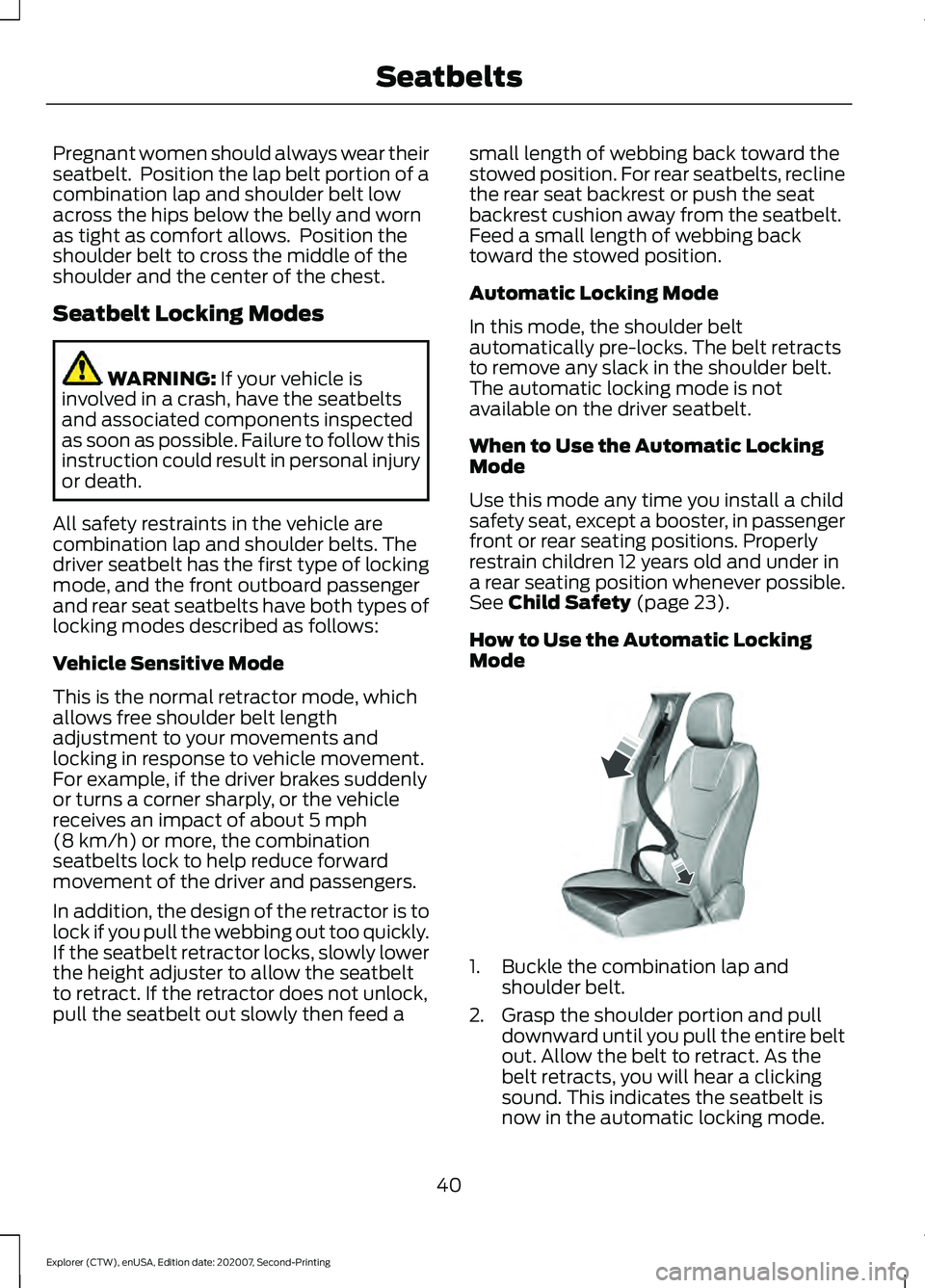
How to Use the Automatic Locking
Mode 1. Buckle the combination lap and
shoulder belt.
2. Grasp the shoulder portion and pull downward until you pull the entire belt
out. Allow the belt to retract. As the
belt retracts, you will hear a clicking
sound. This indicates the seatbelt is
now in the automatic locking mode.
40
Explorer (CTW), enUSA, Edition date: 202007, Second-Printing SeatbeltsE142591
Page 60 of 577
GENERAL INFORMATION ON
RADIO FREQUENCIES
This device complies with Part 15 of the
FCC Rules and with Industry Canada
license-exempt RSS standard(s).
Operation is subject to the following two
conditions: (1) This device may not cause
harmful interference, and (2) This device
must accept any interference received,
including interference that may cause
undesired operation.
WARNING: Changes or
modifications not expressively approved
by the party responsible for compliance
could void the user's authority to operate
the equipment. The term "IC:" before the
radio certification number only signifies
that Industry Canada technical
specifications were met.
The typical operating range for your
transmitter is approximately
33 ft (10 m).
Vehicles with the remote start feature will
have a greater range.
One of the following could cause a
decrease in operating range:
• Weather conditions.
• Nearby radio towers.
• Structures around the vehicle.
• Other vehicles parked next to your
vehicle.
The radio frequency used by your remote
control can also be used by other radio
transmitters, for example amateur radios,
medical equipment, wireless headphones,
wireless remote controls, cell phones,
battery chargers and alarm systems. If the
frequencies are jammed, you will not be
able to use your remote control. You can
lock and unlock the doors with the key.
Note: Make sure to lock your vehicle before
leaving it unattended. Note:
If you are in range, the remote control
will operate if you press any button
unintentionally.
Note: The remote control contains sensitive
electrical components. Exposure to moisture
or impact may cause permanent damage.
Intelligent Access
(If Equipped)
The system uses a radio frequency signal
to communicate with your vehicle and
authorize your vehicle to unlock when one
of the following conditions are met:
• You activate the front exterior door
handle switch.
• You press the luggage compartment
button.
• You press a button on the transmitter.
If excessive radio frequency interference
is present in the area or if the transmitter
battery is low, you may need to
mechanically unlock your door. You can
use the mechanical key blade in your
intelligent access key to open the driver
door in this situation. See
Remote
Control (page 57).
REMOTE CONTROL
Integrated Keyhead Transmitter
Use the key blade to start your vehicle and
unlock or lock the driver door from outside
your vehicle. The integrated keyhead
transmitter functions as a programmed
ignition key that operates all the locks and
starts your vehicle, as well as a remote
control.
57
Explorer (CTW), enUSA, Edition date: 202007, Second-Printing Keys and Remote Controls
Page 200 of 577
•
Incorrect fuel for climatic conditions.
• Incorrect engine oil viscosity for
climactic conditions.
Note: Some vehicles have a lifetime fuel
filter that is integrated with the fuel tank.
Regular maintenance or replacement is not
needed.
Note: If these checks do not help you
correct the concern, have your vehicle
checked as soon as possible.
Noise Emissions Warranty,
Prohibited Tampering Acts and
Maintenance
On January 1, 1978, Federal regulation
became effective governing the noise
emission on trucks over 10,000 lb
(4,536 kg) Gross Vehicle Weight Rating
(GVWR). The preceding statements
concerning prohibited tampering acts and
maintenance, and the noise warranty
found in the Warranty Guide, are
applicable to complete chassis cabs over
10,000 lb (4,536 kg)
GVWR.
CATALYTIC CONVERTER WARNING:
Do not park, idle or
drive your vehicle on dry grass or other
dry ground cover. The emission system
heats up the engine compartment and
exhaust system, creating the risk of fire. WARNING:
The normal operating
temperature of the exhaust system is
very high. Never work around or attempt
to repair any part of the exhaust system
until it has cooled. Use special care when
working around the catalytic converter.
The catalytic converter heats up to a very
high temperature after only a short
period of engine operation and stays hot
after the engine is switched off. WARNING:
Exhaust leaks may
result in entry of harmful and potentially
lethal fumes into the passenger
compartment. If you smell exhaust
fumes inside your vehicle, have your
vehicle inspected immediately. Do not
drive if you smell exhaust fumes.
Your vehicle has various emission control
components and a catalytic converter that
enables it to comply with applicable
exhaust emission standards.
To make sure that the catalytic converter
and other emission control components
continue to work properly:
• Do not crank the engine for more than
10 seconds at a time.
• Do not run the engine with a spark plug
lead disconnected.
• Do not push-start or tow-start your
vehicle. Use booster cables. See Jump
Starting the Vehicle
(page 300).
• Use only the specified fuel listed.
• Do not switch the ignition off when your
vehicle is moving.
• Avoid running out of fuel.
• Have the items listed in scheduled
maintenance information performed
according to the specified schedule.
Note: Resulting component damage may
not be covered by the vehicle Warranty.
The scheduled maintenance items listed
in scheduled maintenance information are
essential to the life and performance of
your vehicle and to its emissions system.
If you use anything other than Ford,
Motorcraft or Ford-authorized parts for
maintenance replacements or for service
of components affecting emission control,
such non-Ford parts should be equivalent
to genuine Ford Motor Company parts in
performance and durability.
197
Explorer (CTW), enUSA, Edition date: 202007, Second-Printing Engine Emission Control
Page 217 of 577
GENERAL INFORMATION
Note:
Occasional brake noise is normal. If
a metal-to-metal, continuous grinding or
continuous squeal sound is present, the
brake linings may be worn-out and an
authorized dealer should check them. If the
vehicle has continuous vibration or shudder
in the steering wheel while braking, an
authorized dealer should check your vehicle.
Note: Brake dust may accumulate on the
wheels, even under normal driving
conditions. Some dust is inevitable as the
brakes wear and does not contribute to
brake noise. See Cleaning the Wheels
(page 348).
Wet brakes result in reduced braking
efficiency. Gently press the brake pedal a
few times when driving from a car wash or
standing water to dry the brakes.
Brake Over Accelerator
In the event the accelerator pedal
becomes stuck or entrapped, apply steady
and firm pressure to the brake pedal to
slow the vehicle and reduce engine power.
If you experience this condition, apply the
brakes and bring your vehicle to a safe
stop. Switch the engine off, move the
transmission to park (P) and apply the
parking brake. Inspect the accelerator
pedal and the area around it for any items
or debris that may be obstructing its
movement. If none are found and the
condition persists, have your vehicle towed
to the nearest authorized dealer.
Emergency Brake Assist
Emergency brake assist detects when you
brake heavily by measuring the rate at
which you press the brake pedal. It
provides maximum braking efficiency as
long as you press the pedal. Emergency
brake assist can reduce stopping distances
in critical situations. Anti-lock Brake System
This system helps you maintain steering
control during emergency stops by keeping
the brakes from locking. This lamp momentarily
illuminates when you switch the
ignition on or apply the parking
brake. If the light does not illuminate
during start up, remains on or flashes,
except when you switch the ignition on or
apply the parking brake, the anti-lock
braking system may be disabled. Have the
system checked by an authorized dealer.
If the anti-lock brake system is disabled,
normal braking is still effective. See
Warning Lamps and Indicators (page
107).
Note: Indicators vary depending on region. This lamp also illuminates
momentarily when you switch
the ignition on or apply the
parking brake to confirm the
lamp is working. If it does not
illuminate when you switch the
ignition on, apply the parking brake, or if it
begins to flash at any time, have the
system checked by an authorized dealer.
If the brake warning lamp illuminates with
the parking brake released, have the
system checked immediately.
Regenerative Braking System
This feature is used to simulate the engine
braking of an internal combustion engine
and assist the standard brake system while
recovering some of the energy of motion
and storing it in the battery to improve fuel
economy. The standard brake system is
designed to fully stop the car if
regenerative braking is not available.
During regenerative braking, the motor is
214
Explorer (CTW), enUSA, Edition date: 202007, Second-Printing Brakes E270480
Page 270 of 577
Note:
You do not need to enter an exact
trailer width measurement. You only need
to confirm that the width of the trailer is
8.2 ft (2.5 m) or less.
If no, the system turns off.
If yes, the menu goes to the next screen.
• Enter length of trailer:
Toggling up or down using the menu
buttons increases or decreases the
measurement by
3 ft (1 m). Select a length
that is equal to or within 3 ft (1 m) of the
actual measured length. For example, if
the actual measured length is 25 ft (7.6 m),
toggle the length in the menu to 8 m or 27
ft. When you enter the length of the trailer,
this saves the system setup.
Note: When you connect a trailer, but do
not setup a trailer in the blind spot
information system, the system turns off
and a warning appears in the information
display.
Note: If the trailer is a bike rack or cargo
rack with electrical lighting, enter a length
of
3 ft (1 m). Cross Traffic Alert remains on
for trailers with a length of 3 ft (1 m) or less.
Note: The system requires proper
measurement and measurement entry to
function as designed.
System Operation
If you select a trailer in the information
display prior to connecting a trailer, the
system loads that configuration and the
information display shows a message
when you connect the trailer. A second
message appears stating cross traffic alert
is off, unless a trailer is set up with a length
of
3 ft (1 m). The blind spot information
system with trailer tow still functions
normally when driving forward. If you connect a trailer, a message appears
indicating that you attached a trailer. If you
have not selected a trailer previously,
another message appears requesting you
to select one of the trailers in the list or add
a new trailer. The blind spot information
system with trailer tow does not function
without a trailer selected. If you do not
select a trailer, a message appears in the
information display stating it has
deactivated the system. This message
might not appear until your vehicle speed
reaches
22 mph (35 km/h).
The blind spot information system with
trailer tow activates when driving forward
for that particular trailer set up. If you cycle
the ignition, the blind spot information
system with trailer tow continues to
function using the last trailer you selected.
Trailer Considerations
The system works with a trailer with a front
width of
8.2 ft (2.5 m) or less, and a total
length from the trailer hitch ball to the rear
of the trailer of
33 ft (10 m) or less.
Some trailers could cause a slight change
in system performance:
• Wide box trailers, especially those
wider than the towing vehicle, could
cause false alerts to occur when driving
next to infrastructure or near parked
cars. A false alert could also occur
while making a 90-degree turn or
driving through a roundabout.
• Wide trailers that have a total length
greater than
20 ft (6 m) could cause
delayed alerts when a vehicle is
passing at high speeds.
267
Explorer (CTW), enUSA, Edition date: 202007, Second-Printing Driving Aids
Page 288 of 577
be used for safe control of towed
vehicles and for trailers where the
Gross Combined Weight of the
towing vehicle plus the trailer
exceed the Gross Vehicle Weight
Rating of the towing vehicle.
The gross combined weight must
never exceed the Gross Combined
Weight Rating.
Note:
For trailer towing
information refer to the RV and
Trailer Towing Guide available at
an authorized dealer. WARNING: Do not exceed
the GVWR or the GAWR
specified on the certification
label. WARNING:
Do not use
replacement tires with lower
load carrying capacities than the
original tires because they may
lower your vehicle's GVWR and
GAWR limitations. Replacement
tires with a higher limit than the
original tires do not increase the
GVWR and GAWR limitations. WARNING: Exceeding any
vehicle weight rating can
adversely affect the
performance and handling of
your vehicle, cause vehicle
damage and can result in the
loss of control of your vehicle,
serious personal injury or death. Steps for determining the
correct load limit:
1. Locate the statement "The
combined weight of occupants
and cargo should never exceed
XXX kg or XXX lb." on your
vehicle ’s placard.
2. Determine the combined
weight of the driver and
passengers that will be riding
in your vehicle.
3. Subtract the combined weight
of the driver and passengers
from XXX kg or XXX lb.
4. The resulting figure equals the
available amount of cargo and
luggage load capacity. For
example, if the “XXX” amount
equals 1,400 lb. and there will
be five 150 lb. passengers in
your vehicle, the amount of
available cargo and luggage
load capacity is 650 lb.
(1400-750 (5 x 150) = 650 lb.)
5. Determine the combined
weight of luggage and cargo
being loaded on the vehicle.
That weight may not safely
exceed the available cargo and
luggage load capacity
calculated in Step 4.
6. If your vehicle will be towing a
trailer, load from your trailer
will be transferred to your
vehicle. Consult this manual to
determine how this reduces the
available cargo and luggage
load capacity of your vehicle.
285
Explorer (CTW), enUSA, Edition date: 202007, Second-Printing Load Carrying
Page 291 of 577
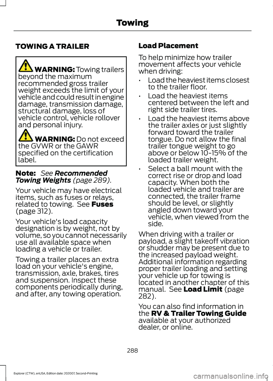
TOWING A TRAILER
WARNING: Towing trailers
beyond the maximum
recommended gross trailer
weight exceeds the limit of your
vehicle and could result in engine
damage, transmission damage,
structural damage, loss of
vehicle control, vehicle rollover
and personal injury. WARNING:
Do not exceed
the GVWR or the GAWR
specified on the certification
label.
Note: See
Recommended
Towing Weights (page 289).
Your vehicle may have electrical
items, such as fuses or relays,
related to towing. See
Fuses
(page 312).
Your vehicle's load capacity
designation is by weight, not by
volume, so you cannot necessarily
use all available space when
loading a vehicle or trailer.
Towing a trailer places an extra
load on your vehicle's engine,
transmission, axle, brakes, tires
and suspension. Inspect these
components periodically during,
and after, any towing operation. Load Placement
To help minimize how trailer
movement affects your vehicle
when driving:
•
Load the heaviest items closest
to the trailer floor.
• Load the heaviest items
centered between the left and
right side trailer tires.
• Load the heaviest items above
the trailer axles or just slightly
forward toward the trailer
tongue. Do not allow the final
trailer tongue weight to go
above or below 10-15% of the
loaded trailer weight.
• Select a ball mount with the
correct rise or drop and load
capacity. When both the
loaded vehicle and trailer are
connected, the trailer frame
should be level, or slightly
angled down toward your
vehicle, when viewed from the
side.
When driving with a trailer or
payload, a slight takeoff vibration
or shudder may be present due to
the increased payload weight.
Additional information regarding
proper trailer loading and setting
your vehicle up for towing is
located in another chapter of this
manual. See
Load Limit (page
282).
You can also find information in
the
RV & Trailer Towing Guide
available at your authorized
dealer, or online.
288
Explorer (CTW), enUSA, Edition date: 202007, Second-Printing Towing
Page 293 of 577
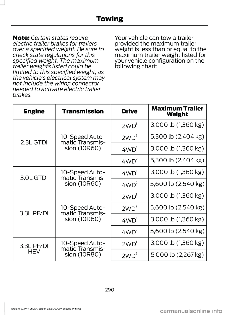
Note:
Certain states require
electric trailer brakes for trailers
over a specified weight. Be sure to
check state regulations for this
specified weight. The maximum
trailer weights listed could be
limited to this specified weight, as
the vehicle ’s electrical system may
not include the wiring connector
needed to activate electric trailer
brakes. Your vehicle can tow a trailer
provided the maximum trailer
weight is less than or equal to the
maximum trailer weight listed for
your vehicle configuration on the
following chart: Maximum Trailer
Weight
Drive
Transmission
Engine
3,000 lb (1,360 kg)
2WD 1
10-Speed Auto-
matic Transmis- sion (10R60)
2.3L GTDI 5,300 lb (2,404 kg)
2WD 2
3,000 lb (1,360 kg)
4WD 1
5,300 lb (2,404 kg)
4WD 2
3,000 lb (1,360 kg)
4WD 1
10-Speed Auto-
matic Transmis- sion (10R60)
3.0L GTDI
5,600 lb (2,540 kg)
4WD 2
3,000 lb (1,360 kg)
2WD 1
10-Speed Auto-
matic Transmis- sion (10R60)
3.3L PF/DI 5,600 lb (2,540 kg)
2WD 2
3,000 lb (1,360 kg)
4WD 1
5,600 lb (2,540 kg)
4WD 2
3,000 lb (1,360 kg)
2WD 1
10-Speed Auto-
matic Transmis- sion (10R80)
3.3L PF/DI
HEV 5,000 lb (2,267 kg)
2WD 2
290
Explorer (CTW), enUSA, Edition date: 202007, Second-Printing Towing