FORD EXPLORER SPORT TRAC 2001 Owners Manual
EXPLORER SPORT TRAC 2001
FORD
FORD
https://www.carmanualsonline.info/img/11/58757/w960_58757-0.png
FORD EXPLORER SPORT TRAC 2001 Owners Manual
Trending: fuel pressure, tow, clock setting, coolant capacity, radiator cap, fog light, wheelbase
Page 161 of 264
FUSES AND RELAYS
Fuses
If electrical components in the
vehicle are not working, a fuse may
have blown. Blown fuses are
identified by a broken wire within
the fuse. Check the appropriate
fuses before replacing any electrical
components.
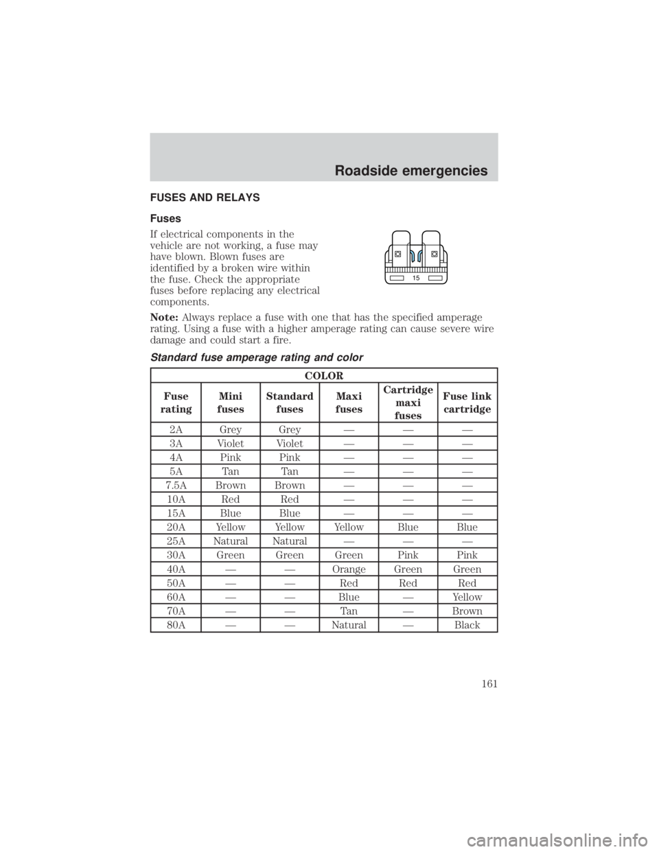
Note:Always replace a fuse with one that has the specified amperage
rating. Using a fuse with a higher amperage rating can cause severe wire
damage and could start a fire.
Standard fuse amperage rating and color
COLOR
Fuse
ratingMini
fusesStandard
fusesMaxi
fusesCartridge
maxi
fusesFuse link
cartridge
2A Grey Grey Ð Ð Ð
3A Violet Violet Ð Ð Ð
4A Pink Pink Ð Ð Ð
5A Tan Tan Ð Ð Ð
7.5A Brown Brown Ð Ð Ð
10A Red Red Ð Ð Ð
15A Blue Blue Ð Ð Ð
20A Yellow Yellow Yellow Blue Blue
25A Natural Natural Ð Ð Ð
30A Green Green Green Pink Pink
40A Ð Ð Orange Green Green
50A Ð Ð Red Red Red
60A Ð Ð Blue Ð Yellow
70A Ð Ð Tan Ð Brown
80A Ð Ð Natural Ð Black
15
Roadside emergencies
161
Page 162 of 264
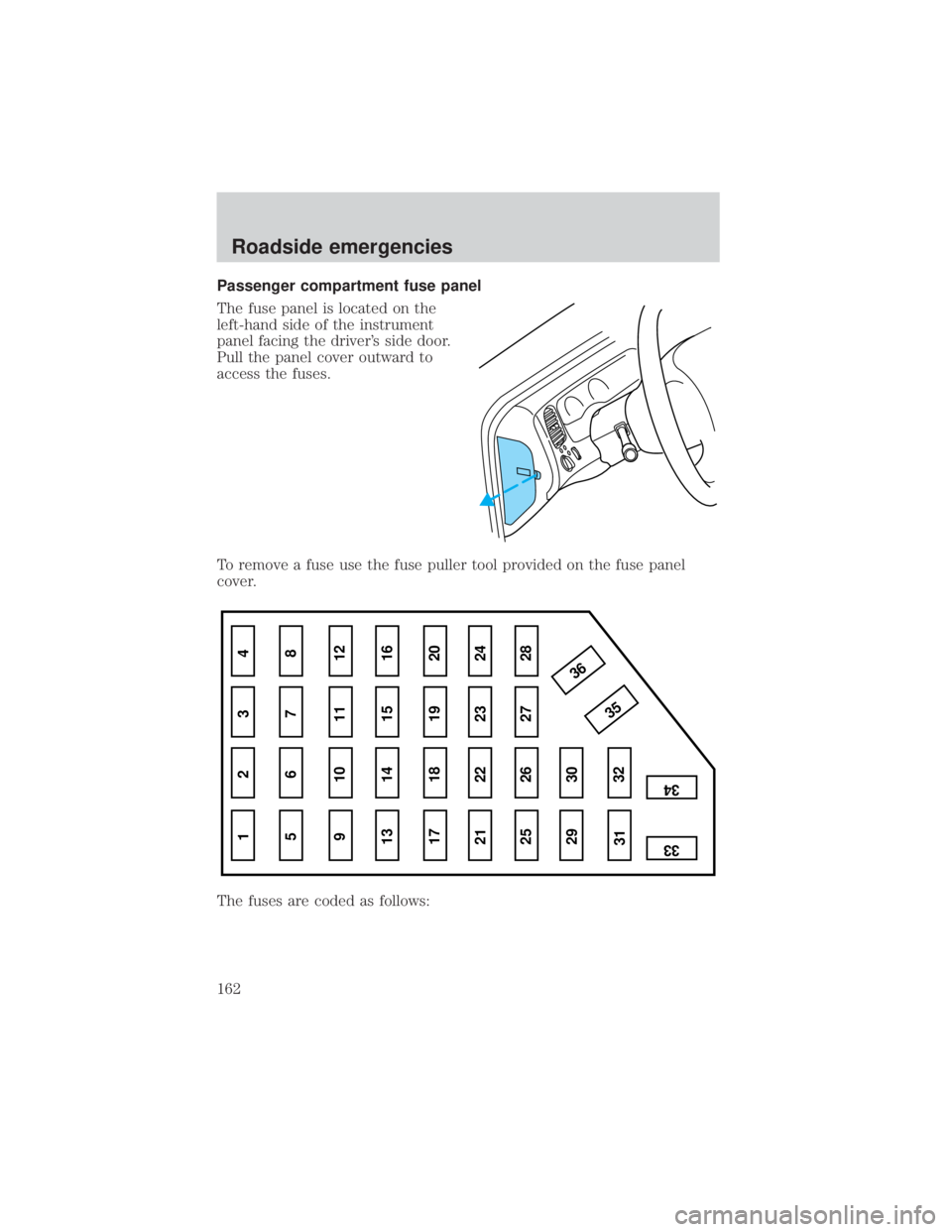
Passenger compartment fuse panel
The fuse panel is located on the
left-hand side of the instrument
panel facing the driver's side door.
Pull the panel cover outward to
access the fuses.
To remove a fuse use the fuse puller tool provided on the fuse panel
cover.
The fuses are coded as follows:
1 234
5 678
9 101112
13 14 15 16
17 18 19 20
21 22 23 24
25 26
29 30
35 36
313233
34
27 28
Roadside emergencies
162
Page 163 of 264
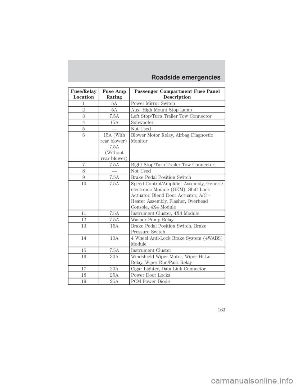
Fuse/Relay
LocationFuse Amp
RatingPassenger Compartment Fuse Panel
Description
1 5A Power Mirror Switch
2 5A Aux. High Mount Stop Lamp
3 7.5A Left Stop/Turn Trailer Tow Connector
4 15A Subwoofer
5 Ð Not Used
6 15A (With
rear blower)
7.5A
(Without
rear blower)Blower Motor Relay, Airbag Diagnostic
Monitor
7 7.5A Right Stop/Turn Trailer Tow Connector
8 Ð Not Used
9 7.5A Brake Pedal Position Switch
10 7.5A Speed Control/Amplifier Assembly, Generic
electronic Module (GEM), Shift Lock
Actuator, Blend Door Actuator, A/C -
Heater Assembly, Flasher, Overhead
Console, 4X4 Module
11 7.5A Instrument Cluster, 4X4 Module
12 7.5A Washer Pump Relay
13 15A Brake Pedal Position Switch, Brake
Pressure Switch
14 10A 4 Wheel Anti-Lock Brake System (4WABS)
Module
15 7.5A Instrument Cluster
16 30A Windshield Wiper Motor, Wiper Hi-Lo
Relay, Wiper Run/Park Relay
17 20A Cigar Lighter, Data Link Connector
18 25A Power Door Locks
19 25A PCM Power Diode
Roadside emergencies
163
Page 164 of 264
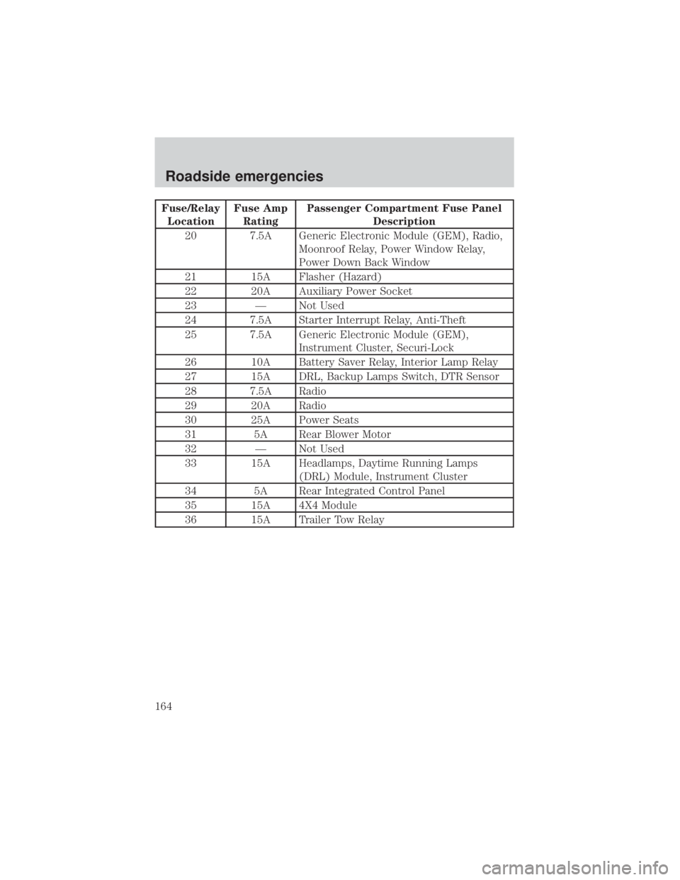
Fuse/Relay
LocationFuse Amp
RatingPassenger Compartment Fuse Panel
Description
20 7.5A Generic Electronic Module (GEM), Radio,
Moonroof Relay, Power Window Relay,
Power Down Back Window
21 15A Flasher (Hazard)
22 20A Auxiliary Power Socket
23 Ð Not Used
24 7.5A Starter Interrupt Relay, Anti-Theft
25 7.5A Generic Electronic Module (GEM),
Instrument Cluster, Securi-Lock
26 10A Battery Saver Relay, Interior Lamp Relay
27 15A DRL, Backup Lamps Switch, DTR Sensor
28 7.5A Radio
29 20A Radio
30 25A Power Seats
31 5A Rear Blower Motor
32 Ð Not Used
33 15A Headlamps, Daytime Running Lamps
(DRL) Module, Instrument Cluster
34 5A Rear Integrated Control Panel
35 15A 4X4 Module
36 15A Trailer Tow Relay
Roadside emergencies
164
Page 165 of 264
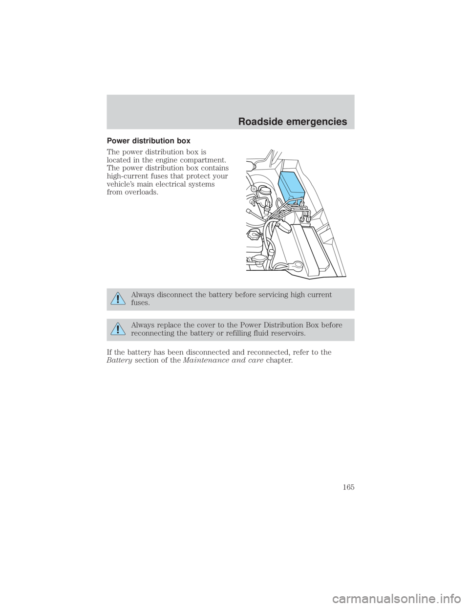
Power distribution box
The power distribution box is
located in the engine compartment.
The power distribution box contains
high-current fuses that protect your
vehicle's main electrical systems
from overloads.
Always disconnect the battery before servicing high current
fuses.
Always replace the cover to the Power Distribution Box before
reconnecting the battery or refilling fluid reservoirs.
If the battery has been disconnected and reconnected, refer to the
Batterysection of theMaintenance and carechapter.
Roadside emergencies
165
Page 166 of 264
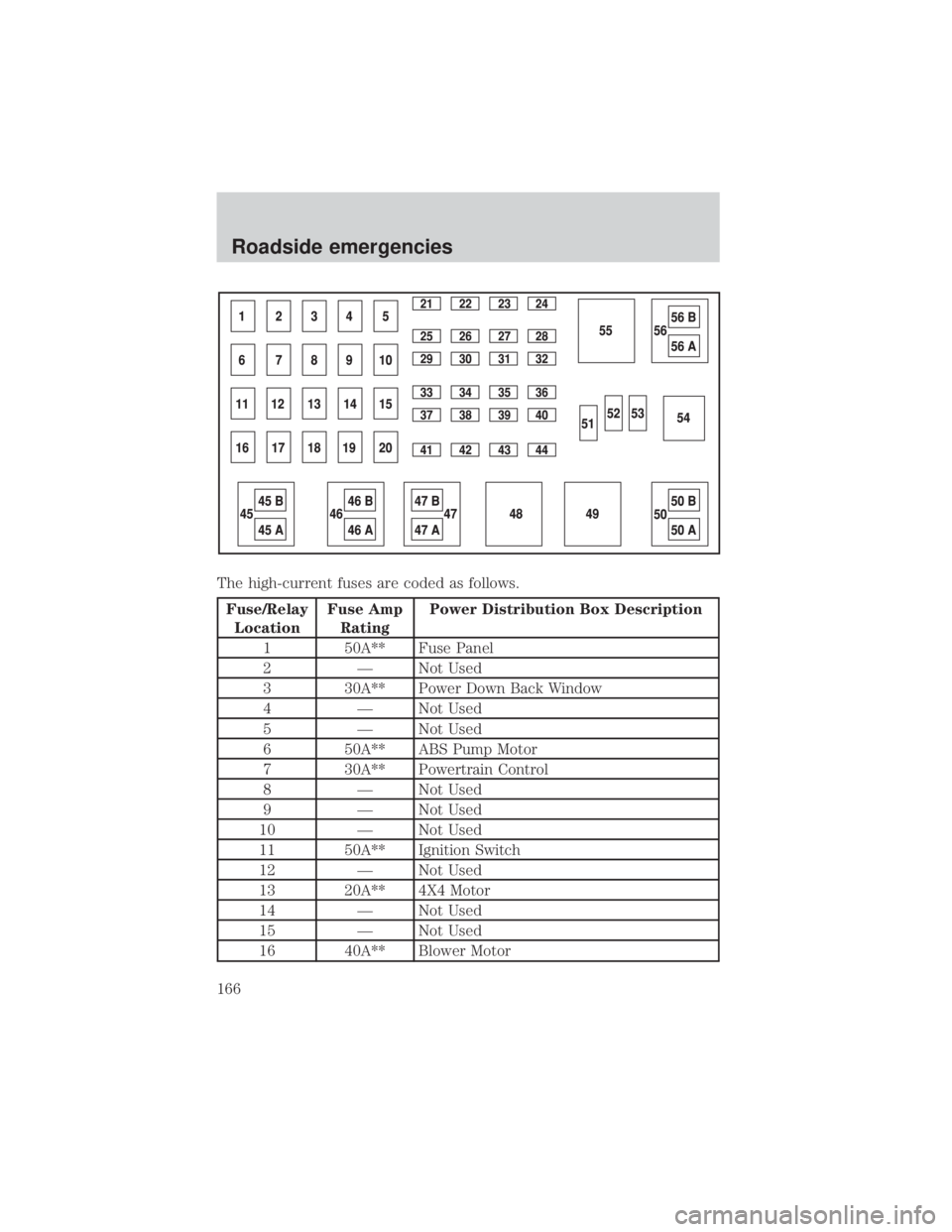
The high-current fuses are coded as follows.
Fuse/Relay
LocationFuse Amp
RatingPower Distribution Box Description
1 50A** Fuse Panel
2 Ð Not Used
3 30A** Power Down Back Window
4 Ð Not Used
5 Ð Not Used
6 50A** ABS Pump Motor
7 30A** Powertrain Control
8 Ð Not Used
9 Ð Not Used
10 Ð Not Used
11 50A** Ignition Switch
12 Ð Not Used
13 20A** 4X4 Motor
14 Ð Not Used
15 Ð Not Used
16 40A** Blower Motor
Roadside emergencies
166
Page 167 of 264
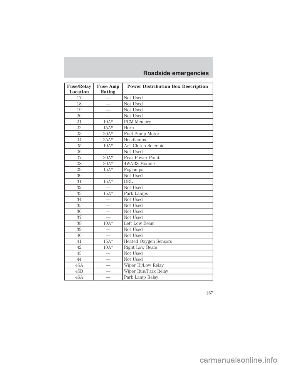
Fuse/Relay
LocationFuse Amp
RatingPower Distribution Box Description
17 Ð Not Used
18 Ð Not Used
19 Ð Not Used
20 Ð Not Used
21 10A* PCM Memory
22 15A* Horn
23 20A* Fuel Pump Motor
24 25A* Headlamps
25 10A* A/C Clutch Solenoid
26 Ð Not Used
27 20A* Rear Power Point
28 30A* 4WABS Module
29 15A* Foglamps
30 Ð Not Used
31 15A* DRL
32 Ð Not Used
33 15A* Park Lamps
34 Ð Not Used
35 Ð Not Used
36 Ð Not Used
37 Ð Not Used
38 10A* Left Low Beam
39 Ð Not Used
40 Ð Not Used
41 15A* Heated Oxygen Sensors
42 10A* Right Low Beam
43 Ð Not Used
44 Ð Not Used
45A Ð Wiper Hi/Low Relay
45B Ð Wiper Run/Park Relay
46A Ð Park Lamp Relay
Roadside emergencies
167
Page 168 of 264
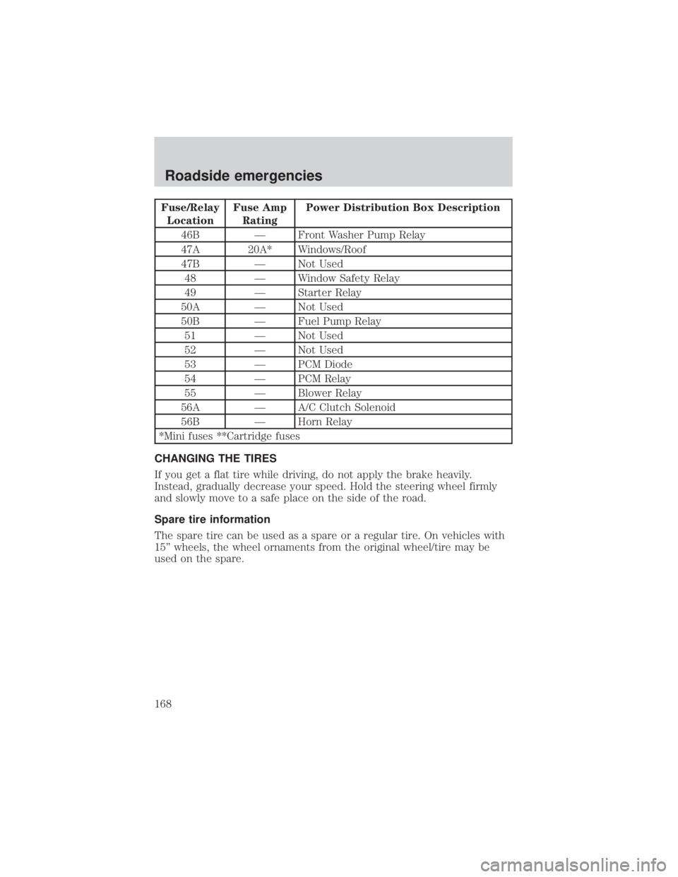
Fuse/Relay
LocationFuse Amp
RatingPower Distribution Box Description
46B Ð Front Washer Pump Relay
47A 20A* Windows/Roof
47B Ð Not Used
48 Ð Window Safety Relay
49 Ð Starter Relay
50A Ð Not Used
50B Ð Fuel Pump Relay
51 Ð Not Used
52 Ð Not Used
53 Ð PCM Diode
54 Ð PCM Relay
55 Ð Blower Relay
56A Ð A/C Clutch Solenoid
56B Ð Horn Relay
*Mini fuses **Cartridge fuses
CHANGING THE TIRES
If you get a flat tire while driving, do not apply the brake heavily.
Instead, gradually decrease your speed. Hold the steering wheel firmly
and slowly move to a safe place on the side of the road.
Spare tire information
The spare tire can be used as a spare or a regular tire. On vehicles with
15º wheels, the wheel ornaments from the original wheel/tire may be
used on the spare.
Roadside emergencies
168
Page 169 of 264
Location of the spare tire and tools
The spare tire and tools for your vehicle are stowed in the following
locations:
Tool Location
Spare tire Under the vehicle, just in front of
the rear bumper
Jack, Jack handle, jack handle
extension, wheel lug nut wrenchIn the passenger side rear cab
compartment behind the access
door in trim panel
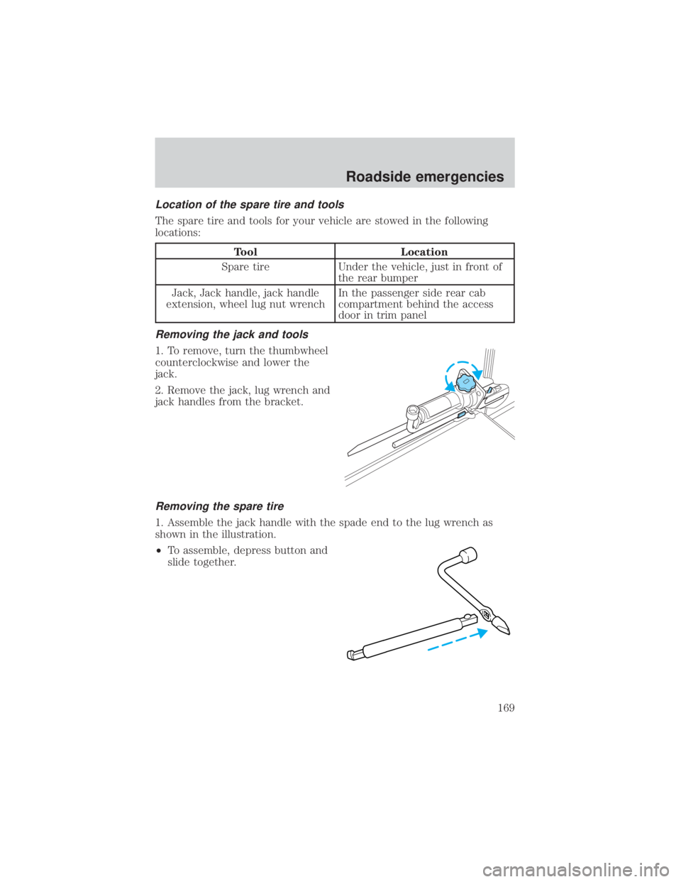
Removing the jack and tools
1. To remove, turn the thumbwheel
counterclockwise and lower the
jack.
2. Remove the jack, lug wrench and
jack handles from the bracket.
Removing the spare tire
1. Assemble the jack handle with the spade end to the lug wrench as
shown in the illustration.
²To assemble, depress button and
slide together.
Roadside emergencies
169
Page 170 of 264
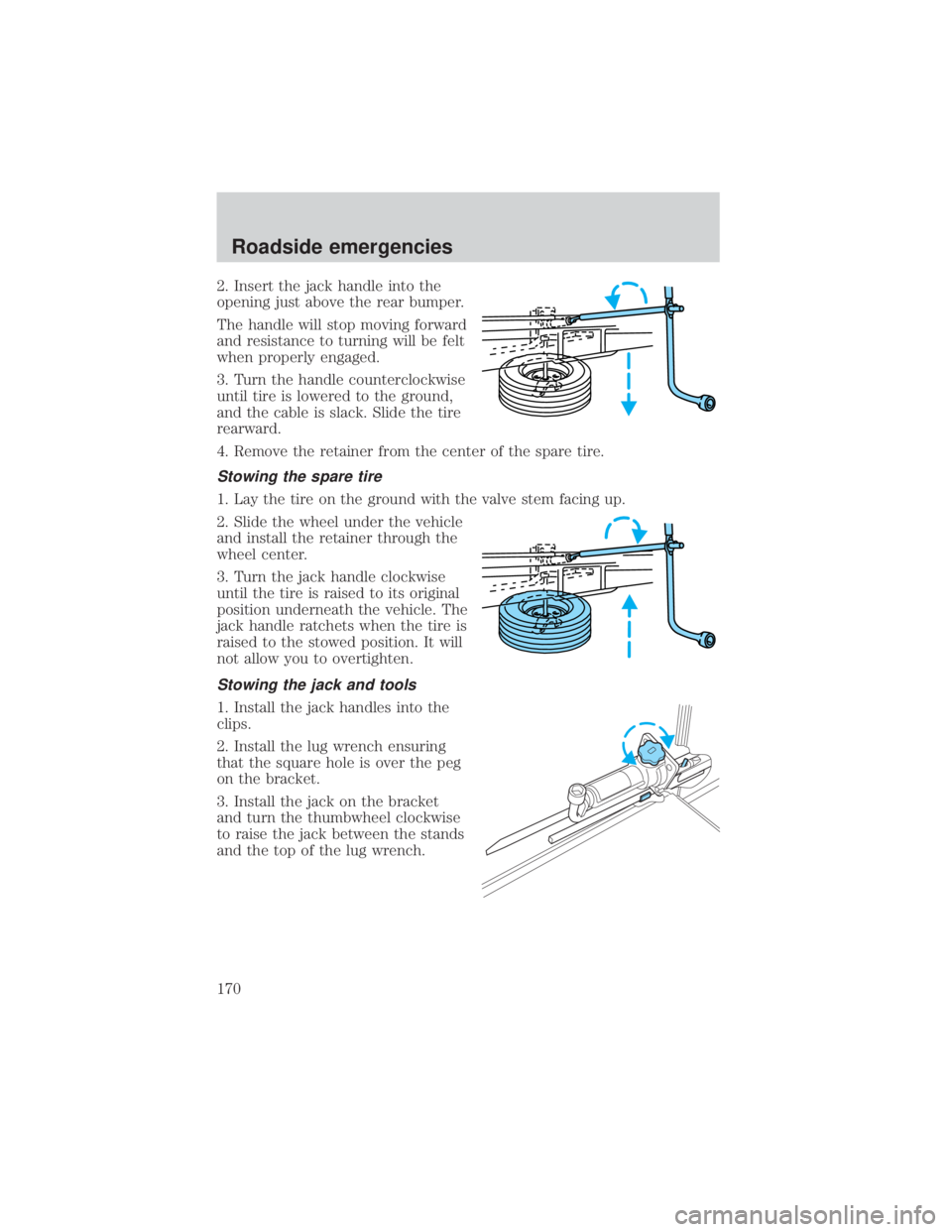
2. Insert the jack handle into the
opening just above the rear bumper.
The handle will stop moving forward
and resistance to turning will be felt
when properly engaged.
3. Turn the handle counterclockwise
until tire is lowered to the ground,
and the cable is slack. Slide the tire
rearward.
4. Remove the retainer from the center of the spare tire.
Stowing the spare tire
1. Lay the tire on the ground with the valve stem facing up.
2. Slide the wheel under the vehicle
and install the retainer through the
wheel center.
3. Turn the jack handle clockwise
until the tire is raised to its original
position underneath the vehicle. The
jack handle ratchets when the tire is
raised to the stowed position. It will
not allow you to overtighten.
Stowing the jack and tools
1. Install the jack handles into the
clips.
2. Install the lug wrench ensuring
that the square hole is over the peg
on the bracket.
3. Install the jack on the bracket
and turn the thumbwheel clockwise
to raise the jack between the stands
and the top of the lug wrench.
Roadside emergencies
170
Trending: tire size, gas mileage, width, park assist, lumbar support, fuel tank capacity, service interval
