tow bar FORD F-150 2019 Owners Manual
[x] Cancel search | Manufacturer: FORD, Model Year: 2019, Model line: F-150, Model: FORD F-150 2019Pages: 644, PDF Size: 14.81 MB
Page 124 of 644
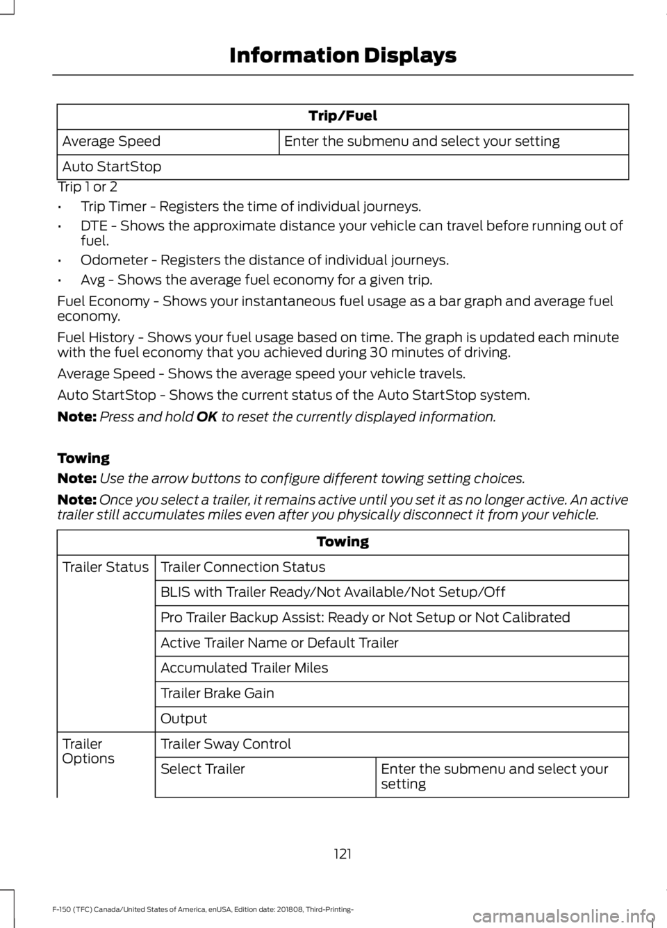
Trip/Fuel
Enter the submenu and select your setting
Average Speed
Auto StartStop
Trip 1 or 2
• Trip Timer - Registers the time of individual journeys.
• DTE - Shows the approximate distance your vehicle can travel before running out of
fuel.
• Odometer - Registers the distance of individual journeys.
• Avg - Shows the average fuel economy for a given trip.
Fuel Economy - Shows your instantaneous fuel usage as a bar graph and average fuel
economy.
Fuel History - Shows your fuel usage based on time. The graph is updated each minute
with the fuel economy that you achieved during 30 minutes of driving.
Average Speed - Shows the average speed your vehicle travels.
Auto StartStop - Shows the current status of the Auto StartStop system.
Note: Press and hold OK to reset the currently displayed information.
Towing
Note: Use the arrow buttons to configure different towing setting choices.
Note: Once you select a trailer, it remains active until you set it as no longer active. An active
trailer still accumulates miles even after you physically disconnect it from your vehicle. Towing
Trailer Connection Status
Trailer Status
BLIS with Trailer Ready/Not Available/Not Setup/Off
Pro Trailer Backup Assist: Ready or Not Setup or Not Calibrated
Active Trailer Name or Default Trailer
Accumulated Trailer Miles
Trailer Brake Gain
Output
Trailer Sway Control
Trailer
Options
Enter the submenu and select your
setting
Select Trailer
121
F-150 (TFC) Canada/United States of America, enUSA, Edition date: 201808, Third-Printing- Information Displays
Page 269 of 644
•
Box trailers that have a width greater
than 8.5 ft (2.6 m) at the front may
cause early alerts when you pass a
vehicle.
• Clam shell or V-Nose box trailers with
a width greater than
8.5 ft (2.6 m) at
the front may cause delayed alerts
when a vehicle traveling the same
speed as your vehicle merges lanes.
System Errors
If the system detects a fault, a warning
lamp illuminates and a message displays.
See
Information Messages (page 128).
Switching the System On and Off
You can switch the system off using the
information display.
See General
Information (page 116). When you switch
the system off, a warning lamp illuminates
and a message displays. When you switch
the system on or off, the alert indicators
flash twice.
Note: The system remembers the last
setting when you start your vehicle.
Note: The system may not correctly operate
when towing a trailer. For vehicles with an
approved trailer tow module and tow bar,
the system turns off when you attach a
trailer. For vehicles with an aftermarket
trailer tow module or tow bar, we
recommend that you switch the system off
when you attach a trailer.
To permanently switch the system off,
contact an authorized dealer. CROSS TRAFFIC ALERT
(IF
EQUIPPED) WARNING:
Do not use the cross
traffic alert system as a replacement for
using the interior and exterior mirrors or
looking over your shoulder before
reversing out of a parking space. The
cross traffic alert system is not a
replacement for careful driving. WARNING:
The system may not
operate properly during severe weather
conditions, for example snow, ice, heavy
rain and spray. Always drive with due
care and attention. Failure to take care
may result in a crash.
The system is designed to alert you of
vehicles approaching from the sides when
you shift into reverse (R).
Using the Cross Traffic Alert
System
The system is designed to detect vehicles
that approach with a speed up to
37 mph
(60 km/h). Coverage decreases when the
sensors are partially, mostly or fully
obstructed. Slowly reversing helps increase
the coverage area and effectiveness.
The system turns on when you start the
engine and you shift into reverse (R). The
system turns off when you shift out of
reverse (R).
266
F-150 (TFC) Canada/United States of America, enUSA, Edition date: 201808, Third-Printing- Driving Aids
Page 272 of 644
Note:
The system may not correctly operate
when towing a trailer. For vehicles with an
approved trailer tow module and tow bar,
the system turns off when you attach a
trailer. For vehicles with an aftermarket
trailer tow module or tow bar, we
recommend that you switch the system off
when you attach a trailer.
To permanently switch the system off,
contact an authorized dealer.
STEERING
Electric Power Steering (If Equipped) WARNING:
The electric power
steering system has diagnostic checks
that continuously monitor the system. If
a fault is detected, a message displays
in the information display. Stop your
vehicle as soon as it is safe to do so.
Switch the ignition off. After at least 10
seconds, switch the ignition on and
watch the information display for a
steering system warning message. If a
steering system warning message
returns, have the system checked as
soon as possible. WARNING:
If the system detects
an error, you may not feel a difference in
the steering, however a serious condition
may exist. Have your vehicle checked as
soon as possible. Failure to do so may
result in loss of steering control.
Your vehicle has an electric power steering
system, there is no fluid reservoir, no
maintenance is required.
If your vehicle loses electrical power while
you are driving, electric power steering
assistance is lost. The steering system still
operates and you can steer your vehicle
manually. Manually steering your vehicle
requires more effort. Extreme continuous steering may increase
the effort required for you to steer your
vehicle, this increased effort prevents
overheating and permanent damage to
the steering system. You do not lose the
ability to steer your vehicle manually.
Typical steering and driving maneuvers
allow the system to cool and return to
normal operation.
Steering Tips
If the steering wanders or pulls, check for:
•
Correct tire pressures.
• Uneven tire wear.
• Loose or worn suspension
components.
• Loose or worn steering components.
• Improper vehicle alignment.
Note: A high crown in the road or high
crosswinds may also make the steering
seem to wander or pull.
Adaptive Learning
(If Equipped)
The electronic power steering system
adaptive learning helps correct road
irregularities and improves overall handling
and steering feel. It communicates with
the brake system to help operate
advanced stability control and accident
avoidance systems. Additionally, whenever
the battery is disconnected or a new
battery installed, you must drive your
vehicle a short distance before the system
relearns the strategy and reactivates all
systems.
269
F-150 (TFC) Canada/United States of America, enUSA, Edition date: 201808, Third-Printing- Driving Aids
Page 291 of 644
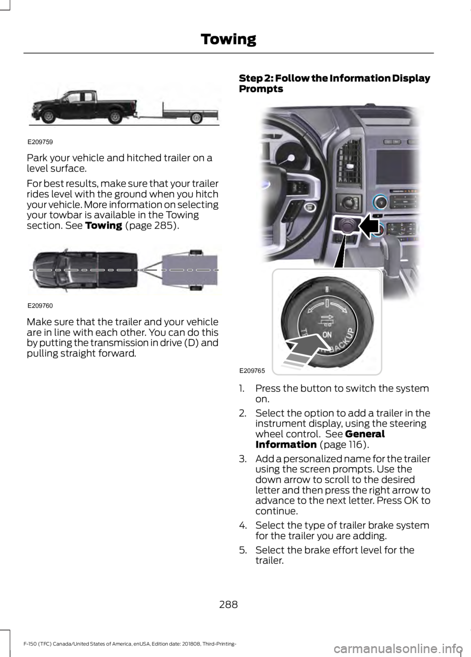
Park your vehicle and hitched trailer on a
level surface.
For best results, make sure that your trailer
rides level with the ground when you hitch
your vehicle. More information on selecting
your towbar is available in the Towing
section. See Towing (page 285).
Make sure that the trailer and your vehicle
are in line with each other. You can do this
by putting the transmission in drive (D) and
pulling straight forward.
Step 2: Follow the Information Display
Prompts
1. Press the button to switch the system
on.
2. Select the option to add a trailer in the
instrument display, using the steering
wheel control. See
General
Information (page 116).
3. Add a personalized name for the trailer
using the screen prompts. Use the
down arrow to scroll to the desired
letter and then press the right arrow to
advance to the next letter. Press OK to
continue.
4. Select the type of trailer brake system for the trailer you are adding.
5. Select the brake effort level for the trailer.
288
F-150 (TFC) Canada/United States of America, enUSA, Edition date: 201808, Third-Printing- TowingE209759 E209760 E209765
Page 296 of 644
Note:
If you still experience issues with the
system's ability to detect the sticker, see
the information in the next section regarding
sticker lost during system operation.
Measurement A has reached maximum or
minimum value:
• The system is designed to work with
drawbars that have a license plate to
hitch ball center measurement of 9 in
(23 cm) to 16 in (41 cm) when installed.
Do not attempt to use drawbars that
have a length outside this range as the
system performance will be degraded
and could cause improper system
function.
• Make sure that the measurement being
made is the horizontal distance only
from license plate and the hitch ball
center. A straight line distance that
includes any vertical rise or drop
increases the measurement and makes
it inaccurate. Inaccurate
measurements degrade system
performance and could cause improper
system function. See step 4 of the
setup instruction to review
measurement instructions.
Measurement B has reached maximum or
minimum value:
• Make sure that the sticker placement
instruction in step 3 of the setup has
been followed. Stickers placed outside
the allowed zone will adversely affect
the system performance and could
cause improper feature function.
• Make sure that the measurement being
made is the horizontal distance only
from center of sticker to the hitch ball
center. A straight line distance that
includes any vertical rise or drop
increases the measurement and
causes an inaccurate value to be
entered into the system. See step 4 of
the setup for additional measurement
instructions. Measurement C has reached maximum or
minimum value:
•
Make sure you follow the sticker
placement instructions in step 3 of the
setup. Stickers placed outside the
allowed zone adversely affect the
system performance and could cause
improper feature function. If you have
met all the criteria for sticker
placement and you see this message,
the sticker is either too far below or too
close to the camera to properly
recognize the sticker. In order for the
system to operate correctly, the sticker
height must be lowered if you receive
the minimum warning or the sticker
height must be raised if you receive the
maximum warning.
• Only one sticker can be placed on the
trailer for correct system function. The
previous sticker must be removed or
covered so only one sticker is visible to
the camera.
• Measurement B and C must be
measured again if a new sticker is
placed on the trailer.
Measurement D has reached maximum or
minimum value:
• Make sure that the measurement being
made is the horizontal distance only
from tailgate to the center of the single
axle or the center of all the axles on the
trailer. See step 4 of the setup for
additional measurement instructions.
The system does not support trailer
lengths outside the range allowed by
the information display.
293
F-150 (TFC) Canada/United States of America, enUSA, Edition date: 201808, Third-Printing- Towing
Page 298 of 644
•
Remove any items that may be
blocking the view of the sticker.
Depending on your trailer configuration
and any equipment mounted to your
trailer, it is possible for the sticker to be
blocked from view of the camera as it
rotates on the hitch ball but not be
blocked during setup. Remove the
obstruction if possible. It may be
necessary to remove the sticker from
its current location if the obstruction
cannot be cleared. Place a new sticker
that is visible to the camera in all
positions of the trailer behind your
vehicle.
• Placing the sticker on a surface angled
away from the vehicle reduces
performance. Use a drawbar that
positions the trailer level to the ground
when attached to the vehicle. This
typically provides a level surface to
mount the sticker. Place the sticker on
a bracket or other object when no level
surface is available.
• Make sure the entire sticker is on a flat
surface that is completely visible to the
camera. Do not fold the sticker over an
edge on the trailer frame. This can
degrade performance.
• Shadows on the sticker may effect
tracking performance under some
lighting conditions. Moving the sticker
to another location within the allowed
placement area may improve
performance. Use the change sticker
option in the information display menu
if you move the sticker.
• You can change your sticker location
by going into the information display
menu, selecting trailer options,
selecting change trailer settings and
then selecting the change sticker
option. The previous sticker must be
removed. ONLY ONE STICKER
SHOULD BE PLACED ON THE
TRAILER FOR CORRECT SYSTEM
FUNCTION. •
The camera system uses the entered
measurements to help locate the
sticker. Inaccurate measurements
reduce the system ’s ability to locate
the sticker. Check the measurements
entered into the system are correct.
Refer to step 4 of setup for instructions
on measurements.
• You can change your measurement by
going into the information display
menu, selecting trailer options,
selecting change trailer setting and
then selecting the change sticker
option. Disregard the prompt to remove
this sticker and continue to the next
step if you only plan to update the
measurements for the current sticker
location.
System does not reverse straight:
• Factors such as the drawbar
connection to the hitch receiver, road
camber, road grade and compliance in
the trailer suspension can influence
how straight the system is able to
reverse your trailer when the knob is
not turned. You can compensate for
the trailer drifting to the right or left by
slowly turning the knob until the trailer
is following your desired path and then
holding the knob in that position. If you
would like to recalibrate the system for
straight backing, you can do so with the
following procedure.
• Go into the information display menu,
select trailer options, select change
trailer setting and then select the
change sticker option. Your saved
measurements display. Do not change
them but continue to confirm
measurements. Once you confirm the
measurements, the system then
prompts you to perform the calibration
procedure.
295
F-150 (TFC) Canada/United States of America, enUSA, Edition date: 201808, Third-Printing- Towing
Page 299 of 644
System consistently shows Pro Trailer
Backup Assist™ Stop now Maximum
trailer angle Press Knob to Exit
:
• The system uses your measurements
to determine sticker position and
establish system limits. Accurate
sticker placement and trailer
measurements provide the best
system performance. If you are
consistently receiving this warning, it is
likely there is an issue with sticker
placement or the entered
measurements. Make sure that the
sticker is placed correctly based on
step 3 and the measurements were
made correctly according to step 4.
The troubleshooting guide for trailer
measurements can also be reviewed
for help in making measurements.
• To change sticker location or change
trailer measurements, go into the
information display menu, select trailer
options, select change trailer setting
and then select the change sticker
option.
• If the sticker location needs to be
changed, the previous sticker must be
removed and a new sticker needs to
be placed on the trailer. ONLY ONE
STICKER SHOULD BE PLACED ON
THE TRAILER FOR PROPER
SYSTEM FUNCTION.
• Disregard the prompt to remove this
sticker and continue to the next step if
you only plan to update the
measurements for the current sticker
location. System consistently shows
Pro Trailer
Backup Assist™ Stop Now Take Control
of Steering Wheel
:
• The system displays this warning when
it can no longer steer the vehicle and
you must take over steering. There are
four reasons why this warning displays
and additional information regarding
the reason for the warning is available
on the center display.
• The steering wheel is touched while
under system control. Avoid touching
the wheel during system operation.
• The maximum speed for feature
operation is exceeded. System
performance is optimized at slower
speeds. Reverse slowly.
• The sticker was lost by the camera
system. Once your vehicle is stopped,
additional warnings indicate the sticker
was lost. Refer to sticker lost
troubleshooting tips.
• An internal condition for system
operation was not met which requires
your vehicle return to manual control
of the steering.
Note: The system is designed to be used
with the same trailer connection every time
the trailer is chosen from the selection
menu. When using a different drawbar or a
different pin hole on drawbars with more
than one, connecting the drawbar to your
vehicle affects the trailer measurements.
Take the measurements again and update
if required.
296
F-150 (TFC) Canada/United States of America, enUSA, Edition date: 201808, Third-Printing- Towing
Page 312 of 644
Calculating the Maximum
Loaded Trailer Weight for Your
Vehicle
1. Start with the gross combined
weight rating for your vehicle
model and axle ratio. See the
previous charts.
2. Subtract all of the following
that apply to your vehicle:
• Vehicle curb weight.
• Hitch hardware weight, for
example a draw bar, ball, locks
or weight distributing hardware.
• Driver weight.
• Passenger(s) weight.
• Payload, cargo and luggage
weight.
• Aftermarket equipment weight.
This equals the maximum loaded
trailer weight for this combination.
Note: The trailer tongue load is
considered part of the payload for
your vehicle. Reduce the total
payload by the final trailer tongue
weight.
Note: Consult an authorized dealer
to determine the maximum trailer
weight allowed for your vehicle if
you are not sure.
ESSENTIAL TOWING CHECKS
Follow these guidelines for safe towing:
• Do not tow a trailer until you drive your
vehicle at least 1,000 mi (1,600 km).
• Consult your local motor vehicle laws
for towing a trailer. •
See the instructions included with
towing accessories for the proper
installation and adjustment
specifications.
• Service your vehicle more frequently if
you tow a trailer. See your scheduled
maintenance information.
See
Scheduled Maintenance (page 562).
• If you use a rental trailer, follow the
instructions the rental agency gives
you.
See
Load limits in the Load Carrying
chapter for load specification terms found
on the tire label and Safety Compliance
label and instructions on calculating your
vehicle's load. See Load Limit (page 277).
Remember to account for the trailer
tongue weight as part of your vehicle load
when calculating the total vehicle weight.
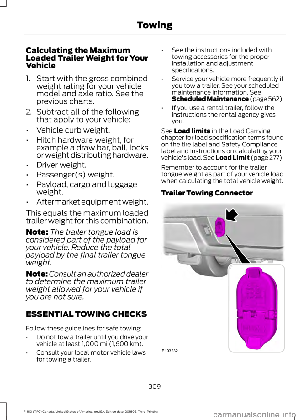
Trailer Towing Connector 309
F-150 (TFC) Canada/United States of America, enUSA, Edition date: 201808, Third-Printing- TowingE193232
Page 313 of 644
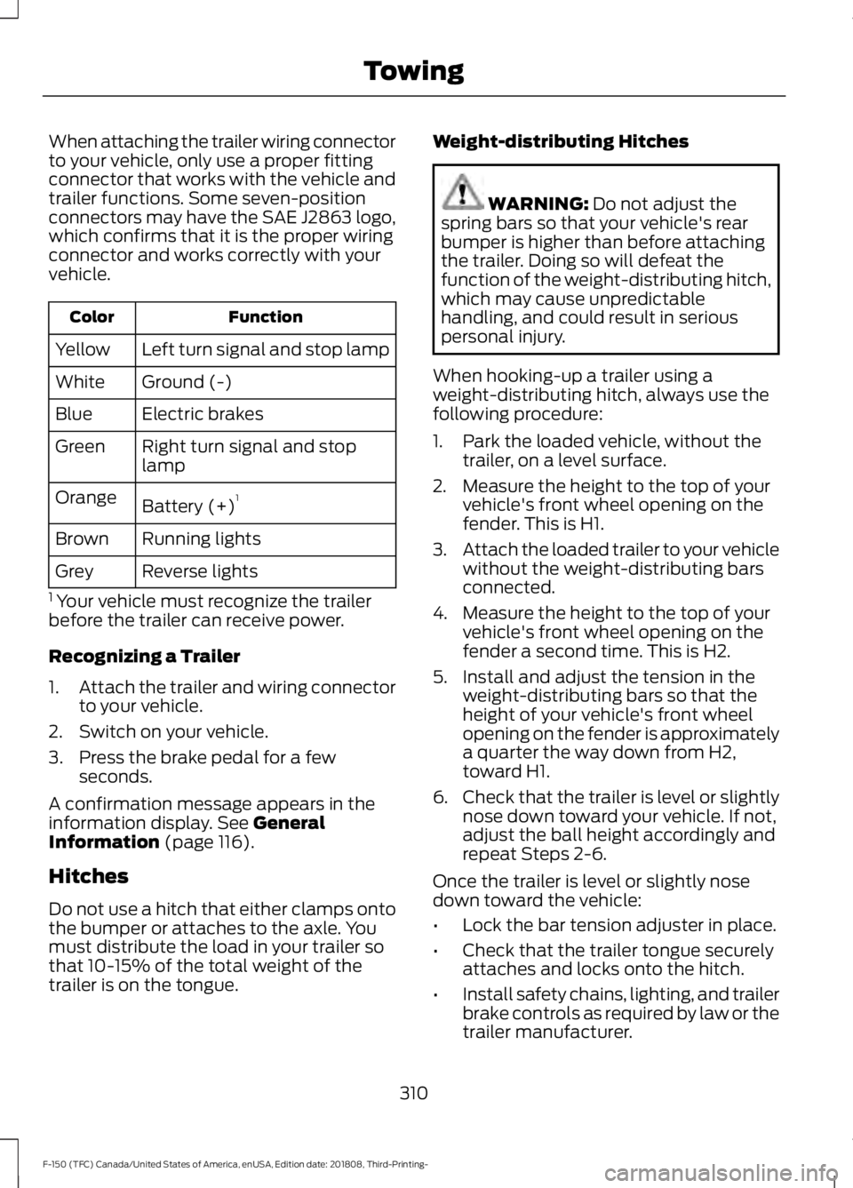
When attaching the trailer wiring connector
to your vehicle, only use a proper fitting
connector that works with the vehicle and
trailer functions. Some seven-position
connectors may have the SAE J2863 logo,
which confirms that it is the proper wiring
connector and works correctly with your
vehicle.
Function
Color
Left turn signal and stop lamp
Yellow
Ground (-)
White
Electric brakes
Blue
Right turn signal and stop
lamp
Green
Battery (+) 1
Orange
Running lights
Brown
Reverse lights
Grey
1 Your vehicle must recognize the trailer
before the trailer can receive power.
Recognizing a Trailer
1. Attach the trailer and wiring connector
to your vehicle.
2. Switch on your vehicle.
3. Press the brake pedal for a few seconds.
A confirmation message appears in the
information display. See General
Information (page 116).
Hitches
Do not use a hitch that either clamps onto
the bumper or attaches to the axle. You
must distribute the load in your trailer so
that 10-15% of the total weight of the
trailer is on the tongue. Weight-distributing Hitches WARNING:
Do not adjust the
spring bars so that your vehicle's rear
bumper is higher than before attaching
the trailer. Doing so will defeat the
function of the weight-distributing hitch,
which may cause unpredictable
handling, and could result in serious
personal injury.
When hooking-up a trailer using a
weight-distributing hitch, always use the
following procedure:
1. Park the loaded vehicle, without the trailer, on a level surface.
2. Measure the height to the top of your vehicle's front wheel opening on the
fender. This is H1.
3. Attach the loaded trailer to your vehicle
without the weight-distributing bars
connected.
4. Measure the height to the top of your vehicle's front wheel opening on the
fender a second time. This is H2.
5. Install and adjust the tension in the weight-distributing bars so that the
height of your vehicle's front wheel
opening on the fender is approximately
a quarter the way down from H2,
toward H1.
6. Check that the trailer is level or slightly
nose down toward your vehicle. If not,
adjust the ball height accordingly and
repeat Steps 2-6.
Once the trailer is level or slightly nose
down toward the vehicle:
• Lock the bar tension adjuster in place.
• Check that the trailer tongue securely
attaches and locks onto the hitch.
• Install safety chains, lighting, and trailer
brake controls as required by law or the
trailer manufacturer.
310
F-150 (TFC) Canada/United States of America, enUSA, Edition date: 201808, Third-Printing- Towing
Page 315 of 644
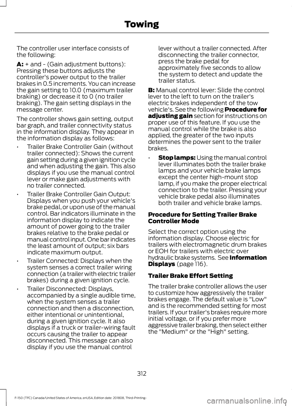
The controller user interface consists of
the following:
A: + and - (Gain adjustment buttons):
Pressing these buttons adjusts the
controller's power output to the trailer
brakes in 0.5 increments. You can increase
the gain setting to 10.0 (maximum trailer
braking) or decrease it to 0 (no trailer
braking). The gain setting displays in the
message center.
The controller shows gain setting, output
bar graph, and trailer connectivity status
in the information display. They appear in
the information display as follows:
• Trailer Brake Controller Gain (without
trailer connected): Shows the current
gain setting during a given ignition cycle
and when adjusting the gain. This also
displays if you use the manual control
lever or make gain adjustments with
no trailer connected.
• Trailer Brake Controller Gain Output:
Displays when you push your vehicle's
brake pedal, or upon use of the manual
control. Bar indicators illuminate in the
information display to indicate the
amount of power going to the trailer
brakes relative to the brake pedal or
manual control input. One bar indicates
the least amount of output; six bars
indicate maximum output.
• Trailer Connected: Displays when the
system senses a correct trailer wiring
connection (a trailer with electric trailer
brakes) during a given ignition cycle.
• Trailer Disconnected: Displays,
accompanied by a single audible time,
when the system senses a trailer
connection and then a disconnection,
either intentional or unintentional,
during a given ignition cycle. It also
displays if a truck or trailer-wiring fault
occurs causing the trailer to appear
disconnected. This message can also
display if you use the manual control lever without a trailer connected. After
disconnecting the trailer connector,
press the brake pedal for
approximately five seconds to allow
the system to detect and update the
trailer status.
B:
Manual control lever: Slide the control
lever to the left to turn on the trailer's
electric brakes independent of the tow
vehicle's. See the following Procedure for
adjusting gain section for instructions on
proper use of this feature. If you use the
manual control while the brake is also
applied, the greater of the two inputs
determines the power sent to the trailer
brakes.
• Stop lamps: Using the manual control
lever illuminates both the trailer brake
lamps and your vehicle brake lamps
except the center high-mount stop
lamp, if you make the proper electrical
connection to the trailer. Pressing your
vehicle brake pedal also illuminates
both trailer and vehicle brake lamps.
Procedure for Setting Trailer Brake
Controller Mode
Select the correct option using the
information display. Choose electric for
trailers with electromagnetic drum brakes
or EOH for trailers with electric over
hydraulic brake systems. See Information
Displays
(page 116).
Trailer Brake Effort Setting
The trailer brake controller allows the user
to customize how aggressively the trailer
brakes engage. The default value is "Low"
and is the recommended setting for most
trailers. If your trailer's brakes require more
initial voltage, or if you prefer more
aggressive trailer braking, then select either
the "Medium" or the "High" setting.
312
F-150 (TFC) Canada/United States of America, enUSA, Edition date: 201808, Third-Printing- Towing