instrument panel FORD F-250 2019 User Guide
[x] Cancel search | Manufacturer: FORD, Model Year: 2019, Model line: F-250, Model: FORD F-250 2019Pages: 666, PDF Size: 13.6 MB
Page 150 of 666
Setting the Blower Motor Speed
Press and release + or - to adjust
the volume of air circulated in
the vehicle.
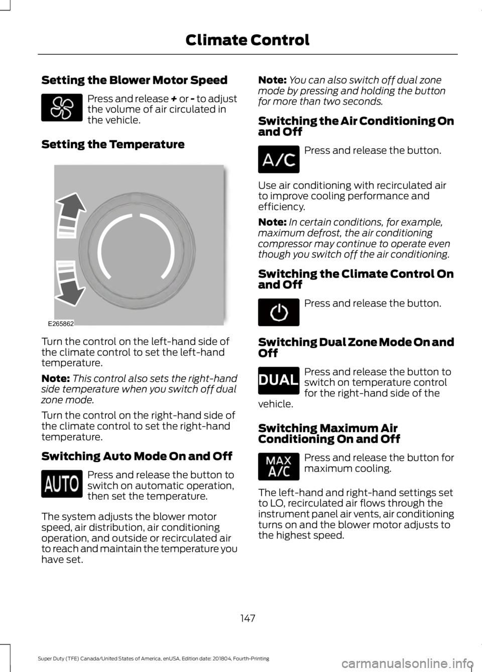
Setting the Temperature Turn the control on the left-hand side of
the climate control to set the left-hand
temperature.
Note:
This control also sets the right-hand
side temperature when you switch off dual
zone mode.
Turn the control on the right-hand side of
the climate control to set the right-hand
temperature.
Switching Auto Mode On and Off Press and release the button to
switch on automatic operation,
then set the temperature.
The system adjusts the blower motor
speed, air distribution, air conditioning
operation, and outside or recirculated air
to reach and maintain the temperature you
have set. Note:
You can also switch off dual zone
mode by pressing and holding the button
for more than two seconds.
Switching the Air Conditioning On
and Off Press and release the button.
Use air conditioning with recirculated air
to improve cooling performance and
efficiency.
Note: In certain conditions, for example,
maximum defrost, the air conditioning
compressor may continue to operate even
though you switch off the air conditioning.
Switching the Climate Control On
and Off Press and release the button.
Switching Dual Zone Mode On and
Off Press and release the button to
switch on temperature control
for the right-hand side of the
vehicle.
Switching Maximum Air
Conditioning On and Off Press and release the button for
maximum cooling.
The left-hand and right-hand settings set
to LO, recirculated air flows through the
instrument panel air vents, air conditioning
turns on and the blower motor adjusts to
the highest speed.
147
Super Duty (TFE) Canada/United States of America, enUSA, Edition date: 201804, Fourth-Printing Climate Control E265862 E265280
Page 151 of 666
Switching Maximum Defrost On
and Off
Press and release the button for
maximum defrosting.
The left-hand and right-hand settings set
to HI, air flows through the windshield air
vents, and the blower motor adjusts to the
highest speed.
You can also use this setting to defog and
clear the windshield of a thin covering of
ice.
Note: To prevent window fogging, you
cannot select recirculated air when
maximum defrost is on.
Note: The heated rear window also turns
on when you select maximum defrost.
Switching Recirculated Air On and
Off Press and release the button to
switch between outside air and
recirculated air.
The air currently in the passenger
compartment recirculates. This may
reduce the time needed to cool the interior,
when used with A/C, and reduce unwanted
odors from entering your vehicle.
Note: Recirculated air may turn off, or
prevent you from switching it on, in all air
flow modes except MAX A/C to reduce the
risk of fogging. Recirculation may also turn
on and off in various air distribution control
combinations during hot weather in order
to improve cooling efficiency.
HINTS ON CONTROLLING THE
INTERIOR CLIMATE
General Hints
Note: Prolonged use of recirculated air may
cause the windows to fog up. Note:
You may feel a small amount of air
from the footwell air vents regardless of the
air distribution setting.
Note: To reduce humidity build-up inside
your vehicle, do not drive with the system
switched off or with recirculated air always
switched on.
Note: Do not place objects under the front
seats as this may interfere with the airflow
to the rear seats.
Note: Remove any snow, ice or leaves from
the air intake area at the base of the
windshield.
Note: To improve the time to reach a
comfortable temperature in hot weather,
drive with the windows open until you feel
cold air through the air vents.
Manual Climate Control
Note: To reduce fogging of the windshield
during humid weather, adjust the air
distribution control to the windshield air
vents position.
Automatic Climate Control
Note: Adjusting the settings when your
vehicle interior is extremely hot or cold is
not necessary. The system automatically
adjusts to heat or cool the interior to your
selected temperature as quickly as possible.
For the system to function efficiently, the
instrument panel and side air vents should
be fully open.
Note: If you select
AUTO during cold
temperatures, the system directs airflow to
the windshield and side window vents. In
addition, the fan may run at a slower speed
until the engine warms up.
Note: If you select
AUTO during hot
temperatures and the inside of the vehicle
is hot, the system automatically uses
recirculated air to maximize interior cooling.
Fan speed may also reduce until the air
cools.
148
Super Duty (TFE) Canada/United States of America, enUSA, Edition date: 201804, Fourth-Printing Climate Control
Page 153 of 666
Recommended Settings for Cooling
Automatic climate control
Manual climate control
Press AUTO.
Adjust the fan speed to the center
setting.
1
Adjust the temperature control to the
desired setting. Use
72°F (22°C) as a
starting point, then adjust the setting as
necessary.
Adjust the temperature control to the
midway point of the cold settings.
2
Direct air to the instrument panel using
the air distribution buttons.
3
Defogging the Side Windows in Cold Weather Automatic climate control
Manual climate control
Press the defrost button.
Direct air to the windshield using the air
distribution buttons.
1
Adjust the temperature control to the
desired setting. Use
72°F (22°C) as a
starting point, then adjust the setting as
necessary.
Press A/C.
2
Adjust the temperature control to the
desired setting.
3
Adjust the fan speed to the highest
setting.
4
HEATED REAR WINDOW
(IF
EQUIPPED) Press the button to clear the rear
window of thin ice and fog. The
heated rear window turns off
after a short period of time. Note:
Do not use harsh chemicals, razor
blades or other sharp objects to clean or
remove decals from the inside of the heated
rear window. The vehicle warranty may not
cover damage to the heated rear window
grid lines.
150
Super Duty (TFE) Canada/United States of America, enUSA, Edition date: 201804, Fourth-Printing Climate ControlE184884
Page 171 of 666
12 V DC Power Point
WARNING: Do not plug optional
electrical accessories into the cigar
lighter socket. Incorrect use of the cigar
lighter can cause damage not covered
by the vehicle warranty, and can result
in fire or serious injury.
Note: When you switch the ignition on, you
can use the socket to power
12 V appliances
with a maximum current rating of 20 A20
amps.
Note: Do not plug in any device that
supplies power to the vehicle through the
power points, this may result in damage to
vehicle systems.
Note: Do not hang any accessory from the
accessory plug.
Note: Do not use the power point over the
vehicle capacity of 12 V DC 240 W or a fuse
may blow.
Note: Always keep the power point caps
closed when not in use.
Do not insert objects other than an
accessory plug into the power point. This
damages the power point and may blow
the fuse.
Run the vehicle for full capacity use of the
power point.
To prevent the battery from running out of
charge:
• Do not use the power point longer than
necessary when the engine is off.
• Do not leave devices plugged in
overnight or when you park your vehicle
for extended periods. 110 V 400 Watt AC Power Point
(If
Equipped) WARNING: Do not keep electrical
devices plugged in the power point
whenever the device is not in use. Do not
use any extension cord with the 110 volt
AC power point, since it will defeat the
safety protection design. Doing so may
cause the power point to overload due
to powering multiple devices that can
reach beyond the 400 watt load limit
and could result in fire or serious injury.
Note: This feature works only when you
have the ignition switched on.
Note: This feature has a maximum output
of 400 watts when the vehicle is in park (P).
Note: While in drive (D), the maximum
outlet output is 300 watts.
Note: When powering electric devices that
require more than 10 watts in vehicles
equipped with keyless start, the engine must
remain running. If the engine is turned off or
you switch the ignition to accessory mode,
plugged in devices will not be charged.
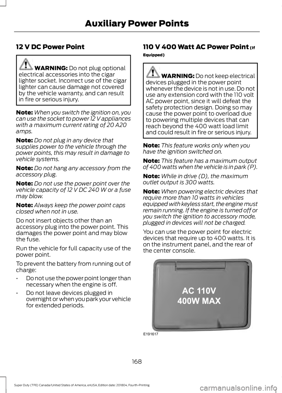
You can use the power point for electric
devices that require up to 400 watts. It is
on the instrument panel, and the rear of
the center console. 168
Super Duty (TFE) Canada/United States of America, enUSA, Edition date: 201804, Fourth-Printing Auxiliary Power PointsE191617
Page 172 of 666
When the indicator light on the power point
is:
•
On: The power point is working, the
ignition is on and a device is plugged
in.
• Off: The power point is off, the ignition
is off or no device is plugged in.
• Flashing: The power point is in fault
mode.
The power outlet temporarily turns off
power when in fault mode if the device
exceeds the 400 watt limit. Unplug your
device and switch the ignition off. Switch
the ignition back on, but do not plug your
device back in. Let the system cool off and
switch the ignition off to reset the fault
mode. Switch the ignition back on and
make sure the indicator light remains on.
You can use the 400 watt power outlet for
these types of electric devices:
• Electric hand drills.
• Rechargeable power tools.
• Video games.
• Laptops.
• Televisions.
Note: Max 400W - when the vehicle is
parked and 300W - when the vehicle is
driving.
Do not use the power point for certain
electric devices, including:
• Cathode-ray, tube-type televisions.
• Motor loads, such as vacuum cleaners,
electric saws and other electric power
tools or compressor-driven
refrigerators.
• Measuring devices, which process
precise data, such as medical
equipment or measuring equipment.
• Other appliances requiring an
extremely stable power supply such as
microcomputer-controlled electric
blankets or touch-sensor lamps. Locations
Note:
Timed power points remain on for 30
minutes if the vehicle is in accessory mode.
If you switch the vehicle off, the timed
power points remain on for 75 minutes.
Power points may be in the following
locations:
• On the instrument panel.
• Inside the center console.
• On the rear of the center console.
• In the seat bin.
169
Super Duty (TFE) Canada/United States of America, enUSA, Edition date: 201804, Fourth-Printing Auxiliary Power Points
Page 216 of 666
For proper operation, make sure that each
hub is fully engaged and that both hub
locks are set to the same position (both
set to LOCK or both set to AUTO). To
engage LOCK, turn the hub locks
completely clockwise; to engage AUTO,
turn the hub locks completely
counterclockwise.
The ESOF 4WD system:
•
provides 4x4 High engagement and
disengagement while the vehicle is
moving.
• is operated by a rotary control located
on the instrument panel that allows
you select 4x2, 4x4 High or 4x4 Low
operation.
• uses auto-manual hub locks that can
be engaged and disengaged
automatically based on the 4x4 mode
selected.
• will increase fuel economy when used
in the hub lock's recommended AUTO
mode.
4WD Indicator Lights
Note: When a 4X4 system fault is present,
the system will typically remain in whichever
4X4 mode was selected prior to the fault
condition occurring. It will not default to 4X2
in all circumstances. When this warning is
displayed, have your vehicle serviced by an
authorized dealer.
4X2 Momentarily illuminates when
2H is selected.
4X4 HIGH Continuously illuminates when
4H is selected. 4X4 LOW Continuously illuminates when
4L is selected.
CHECK 4X4 Displays when a 4X4 fault is
present.
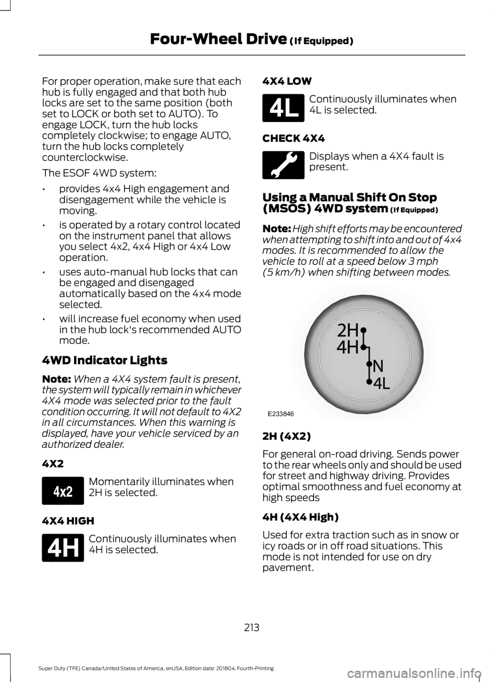
Using a Manual Shift On Stop
(MSOS) 4WD system (If Equipped)
Note: High shift efforts may be encountered
when attempting to shift into and out of 4x4
modes. It is recommended to allow the
vehicle to roll at a speed below
3 mph
(5 km/h) when shifting between modes. 2H (4X2)
For general on-road driving. Sends power
to the rear wheels only and should be used
for street and highway driving. Provides
optimal smoothness and fuel economy at
high speeds
4H (4X4 High)
Used for extra traction such as in snow or
icy roads or in off road situations. This
mode is not intended for use on dry
pavement.
213
Super Duty (TFE) Canada/United States of America, enUSA, Edition date: 201804, Fourth-Printing Four-Wheel Drive
(If Equipped)E163173 E181779 E181780 E233846
Page 228 of 666
You can use this feature with tow/haul or
progressive range selection to provide
further increased engine braking. The
transmission automatically upshifts to
prevent the engine from entering the red
zone on the tachometer. See Automatic
Transmission (page 206).
HINTS ON DRIVING WITH
ANTI-LOCK BRAKES
The anti-lock braking system does not
eliminate the risks when:
• You drive too closely to the vehicle in
front of you.
• Your vehicle is hydroplaning.
• You take corners too fast.
• The road surface is poor.
Note: If the system activates, the brake
pedal may pulse and may travel further.
Maintain pressure on the brake pedal. You
may also hear a noise from the system. This
is normal.
PARKING BRAKE WARNING:
Always set the parking
brake fully and make sure the
transmission is placed in park (P). Failure
to set the parking brake and engage park
could result in vehicle roll-away, property
damage or bodily injury. Turn the ignition
to the lock position and remove the key
whenever you leave your vehicle.
Apply the parking brake whenever your
vehicle is parked. Press the pedal
downward to set the parking brake. The
brake warning lamp in the instrument
cluster will illuminate and remains
illuminated until the parking brake is
released. To release, pull the brake release lever
located at the lower left side of the
instrument panel.
If you are parking your vehicle on a grade
or with a trailer, press and hold the brake
pedal down, then set the parking brake.
There may be a little vehicle movement as
the parking brake sets to hold the vehicle's
weight. This is normal and should be no
reason for concern. If needed, press and
hold the service brake pedal down, then
try reapplying the parking brake. Chock the
wheels if required. If the parking brake
cannot hold the weight of the vehicle, the
parking brake may need to be serviced or
the vehicle may be overloaded.
HILL START ASSIST
WARNING:
The system does not
replace the parking brake. When you
leave your vehicle, always apply the
parking brake. WARNING:
You must remain in
your vehicle when the system turns on.
At all times, you are responsible for
controlling your vehicle, supervising the
system and intervening, if required.
Failure to take care may result in the loss
of control of your vehicle, serious
personal injury or death. WARNING:
The system will turn
off if a malfunction is apparent or if you
rev the engine excessively. Failure to take
care may result in the loss of control of
your vehicle, serious personal injury or
death.
The system makes it easier to pull away
when your vehicle is on a slope without the
need to use the parking brake.
225
Super Duty (TFE) Canada/United States of America, enUSA, Edition date: 201804, Fourth-Printing Brakes
Page 230 of 666
PRINCIPLE OF OPERATION
The traction control system helps avoid
drive wheel spin and loss of traction.
If your vehicle begins to slide, the system
applies the brakes to individual wheels
and, when needed, reduces engine power
at the same time. If the wheels spin when
accelerating on slippery or loose surfaces,
the system reduces engine power in order
to increase traction.
USING TRACTION CONTROL
WARNING: The stability and
traction control light illuminates steadily
if the system detects a failure. Make sure
you did not manually disable the traction
control system using the information
display controls or the switch. If the
stability control and traction control light
is still illuminating steadily, have the
system serviced by an authorized dealer
immediately. Operating your vehicle with
the traction control disabled could lead
to an increased risk of loss of vehicle
control, vehicle rollover, personal injury
and death.
The system automatically turns on each
time you switch the ignition on.
If your vehicle is stuck in mud or snow,
switching traction control off may be
beneficial as this allows the wheels to spin.
Note: When you switch traction control off,
stability control remains fully active.
Note: For additional information on the
traction and stability control systems. See
Using Stability Control
(page 229). Switching the System Off
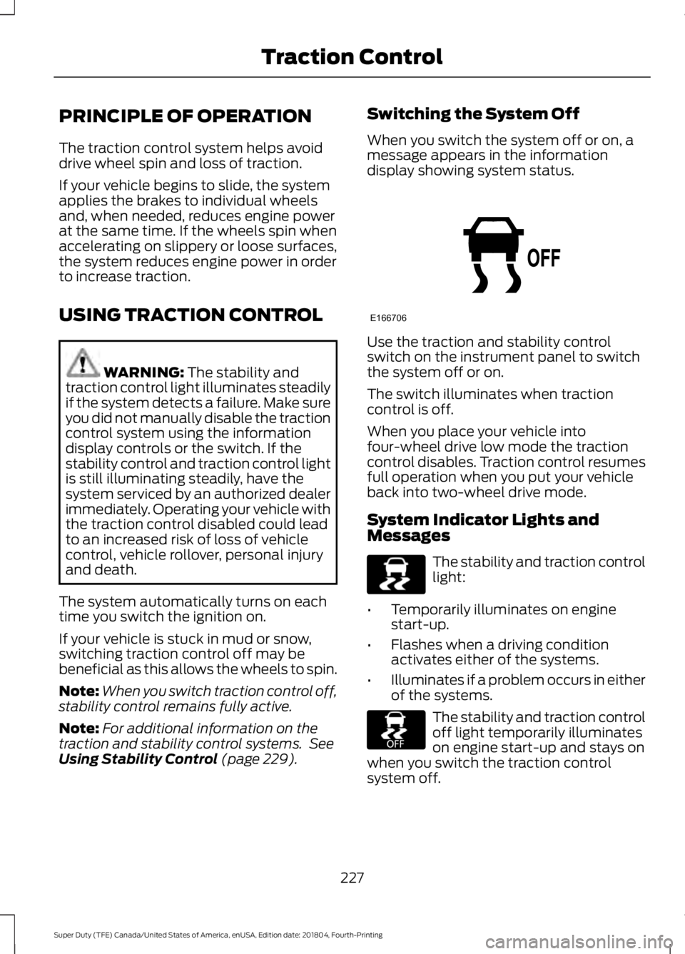
When you switch the system off or on, a
message appears in the information
display showing system status.
Use the traction and stability control
switch on the instrument panel to switch
the system off or on.
The switch illuminates when traction
control is off.
When you place your vehicle into
four-wheel drive low mode the traction
control disables. Traction control resumes
full operation when you put your vehicle
back into two-wheel drive mode.
System Indicator Lights and
Messages
The stability and traction control
light:
• Temporarily illuminates on engine
start-up.
• Flashes when a driving condition
activates either of the systems.
• Illuminates if a problem occurs in either
of the systems. The stability and traction control
off light temporarily illuminates
on engine start-up and stays on
when you switch the traction control
system off.
227
Super Duty (TFE) Canada/United States of America, enUSA, Edition date: 201804, Fourth-Printing Traction ControlE166706 E225465 E225466
Page 232 of 666
Roll Stability Control
The system enhances your vehicle
’s ability
to prevent rollovers by detecting your
vehicle ’s roll motion and the rate at which
it changes by applying the brakes to one
or more wheels individually.
Traction Control
The system enhances your vehicle ’s ability
to maintain traction of the wheels by
detecting and controlling wheel spin. See
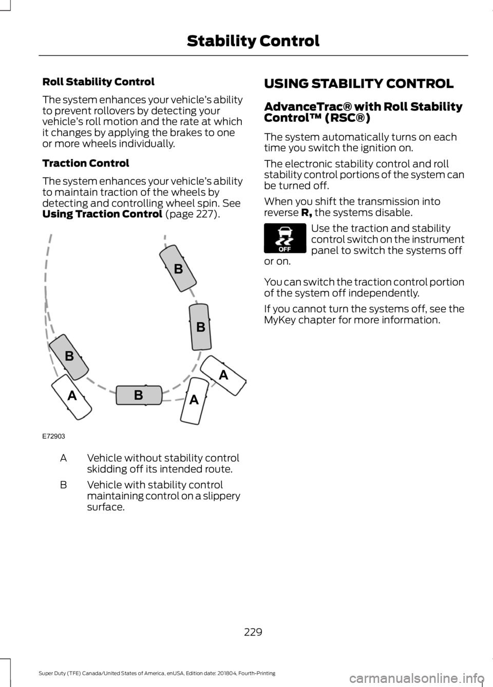
Using Traction Control (page 227). Vehicle without stability control
skidding off its intended route.
A
Vehicle with stability control
maintaining control on a slippery
surface.
B USING STABILITY CONTROL
AdvanceTrac® with Roll Stability
Control
™ (RSC®)
The system automatically turns on each
time you switch the ignition on.
The electronic stability control and roll
stability control portions of the system can
be turned off.
When you shift the transmission into
reverse R, the systems disable. Use the traction and stability
control switch on the instrument
panel to switch the systems off
or on.
You can switch the traction control portion
of the system off independently.
If you cannot turn the systems off, see the
MyKey chapter for more information.
229
Super Duty (TFE) Canada/United States of America, enUSA, Edition date: 201804, Fourth-Printing Stability ControlE72903A
AA
B
BB
B E130458
Page 234 of 666
PRINCIPLE OF OPERATION
WARNING: Hill descent control
cannot control descent in all surface
conditions and circumstances, such as
ice or extremely steep grades. Hill
descent control is a driver assist system
and cannot substitute for good judgment
by the driver. Failure to do so may result
in loss of vehicle control, crash or serious
injury. WARNING:
Hill descent control
does not provide hill hold at zero miles
per hour (0 kilometers per hour). When
stopped, the parking brake must be
applied or the vehicle must be placed in
P
(Park) or it may roll away.
Hill descent control allows the driver to set
and maintain vehicle speed while
descending steep grades in various surface
conditions.
Hill descent control can maintain vehicle
speeds on downhill grades between 2 mph
(3 km/h) and 12 mph (20 km/h). Above 20
mph (32 km/h), the system remains
armed, but descent speed cannot be set
or maintained.
Hill descent control requires a cooling
down interval after a period of sustained
use. The amount of time that the feature
can remain active before cooling varies
with conditions. The system will provide a
warning in the message center and a chime
will sound when the system is about to
disengage for cooling. At this time,
manually apply the brakes as needed to
maintain descent speed. USING HILL DESCENT
CONTROL Press and release the hill
descent button located on the
instrument panel. A light in the
cluster will illuminate and a chime will
sound when this feature is activated.
To increase descent speed, press the
accelerator pedal until the desired speed
is reached. To decrease descent speed,
press the brake pedal until the desired
speed is reached.
Whether accelerating or decelerating, once
the desired descent speed is reached,
remove your feet from the pedals and the
chosen vehicle speed will be maintained.
Note: Noise from the ABS pump motor may
be observed during hill descent control
operation. This is a normal characteristic of
the ABS and should be no reason for
concern.
Hill descent modes
• At speeds below 20 mph (32 km/h):
When the Hill Descent Control switch
is pressed and Hill Descent Control is
active, the Hill Descent Control telltale
will flash.
• At speeds below 20 mph (32 km/h):
When the Hill Descent Control switch
is pressed and conditions are not
correct for hill descent activation, the
Hill Descent Control system will be
enabled, the Hill Descent Control
telltale will be solid and a message will
display in the information display.
• At speeds above 20 mph (32 km/h):
When the Hill Descent Control switch
is pressed, the Hill Descent Control
system will be enabled, the telltale in
the cluster will not be illuminated and
a message will be displayed in the
information display.
231
Super Duty (TFE) Canada/United States of America, enUSA, Edition date: 201804, Fourth-Printing Terrain Control
(If Equipped)E163957