lights FORD F-250 2019 User Guide
[x] Cancel search | Manufacturer: FORD, Model Year: 2019, Model line: F-250, Model: FORD F-250 2019Pages: 666, PDF Size: 13.6 MB
Page 216 of 666
For proper operation, make sure that each
hub is fully engaged and that both hub
locks are set to the same position (both
set to LOCK or both set to AUTO). To
engage LOCK, turn the hub locks
completely clockwise; to engage AUTO,
turn the hub locks completely
counterclockwise.
The ESOF 4WD system:
•
provides 4x4 High engagement and
disengagement while the vehicle is
moving.
• is operated by a rotary control located
on the instrument panel that allows
you select 4x2, 4x4 High or 4x4 Low
operation.
• uses auto-manual hub locks that can
be engaged and disengaged
automatically based on the 4x4 mode
selected.
• will increase fuel economy when used
in the hub lock's recommended AUTO
mode.
4WD Indicator Lights
Note: When a 4X4 system fault is present,
the system will typically remain in whichever
4X4 mode was selected prior to the fault
condition occurring. It will not default to 4X2
in all circumstances. When this warning is
displayed, have your vehicle serviced by an
authorized dealer.
4X2 Momentarily illuminates when
2H is selected.
4X4 HIGH Continuously illuminates when
4H is selected. 4X4 LOW Continuously illuminates when
4L is selected.
CHECK 4X4 Displays when a 4X4 fault is
present.
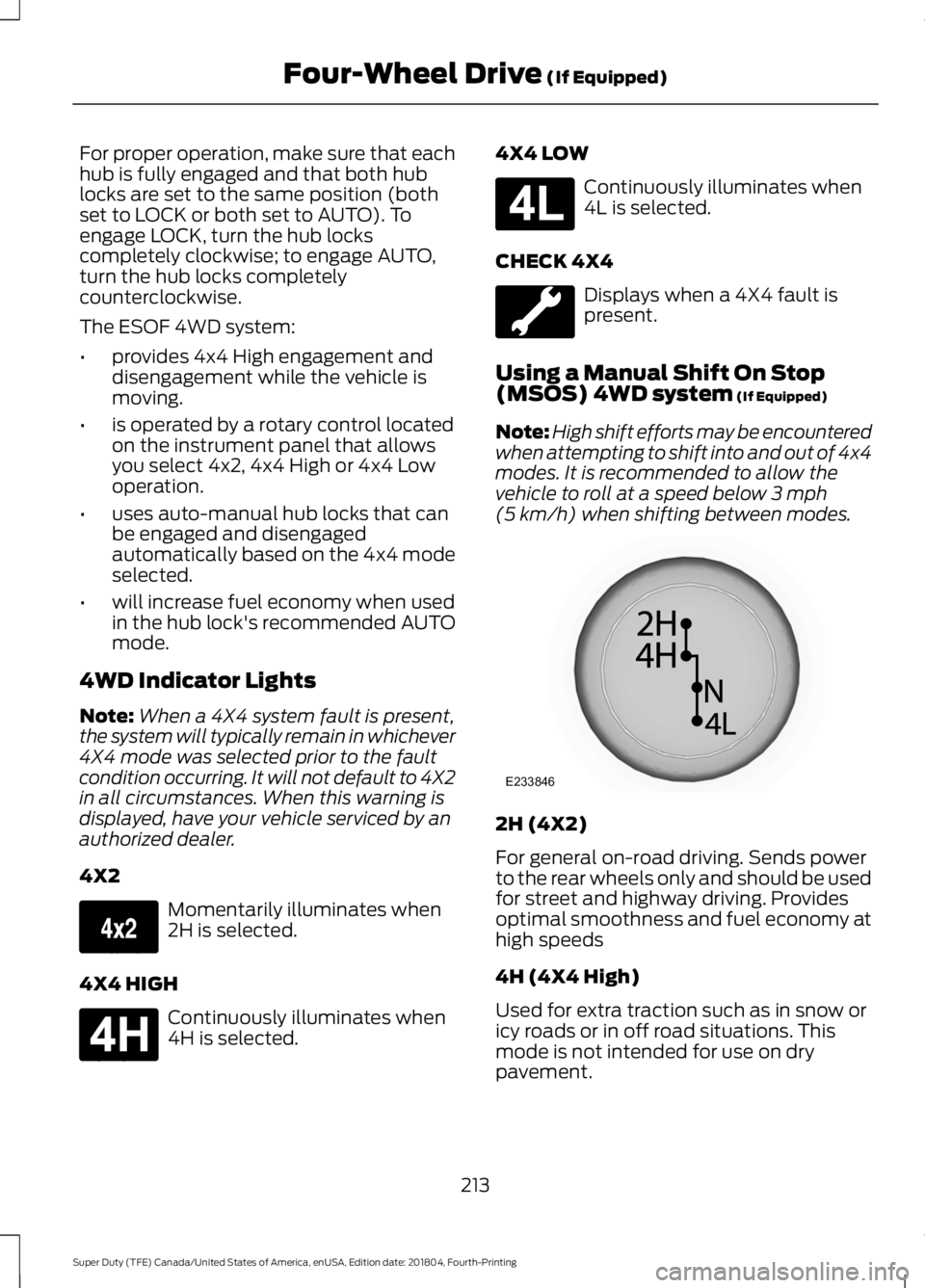
Using a Manual Shift On Stop
(MSOS) 4WD system (If Equipped)
Note: High shift efforts may be encountered
when attempting to shift into and out of 4x4
modes. It is recommended to allow the
vehicle to roll at a speed below
3 mph
(5 km/h) when shifting between modes. 2H (4X2)
For general on-road driving. Sends power
to the rear wheels only and should be used
for street and highway driving. Provides
optimal smoothness and fuel economy at
high speeds
4H (4X4 High)
Used for extra traction such as in snow or
icy roads or in off road situations. This
mode is not intended for use on dry
pavement.
213
Super Duty (TFE) Canada/United States of America, enUSA, Edition date: 201804, Fourth-Printing Four-Wheel Drive
(If Equipped)E163173 E181779 E181780 E233846
Page 229 of 666
When the system is active, your vehicle
remains stationary on the slope for two to
three seconds after you release the brake
pedal. This allows time to move your foot
from the brake to the accelerator pedal.
The system releases the brakes
automatically once the engine has
developed sufficient torque to prevent your
vehicle from rolling down the slope. This
is an advantage when pulling away on a
slope, for example from a car park ramp,
traffic lights or when reversing uphill into
a parking space.
The system activates on any slope that
causes your vehicle to roll.
Note:
There is no warning light to indicate
the system is either on or off.
Using Hill Start Assist
1. Press the brake pedal to bring your vehicle to a complete standstill. Keep
the brake pedal pressed and shift into
first gear when facing uphill or reverse
(R) when facing downhill.
2. If the sensors detect that your vehicle is on a slope, the system activates
automatically.
3. When you remove your foot from the brake pedal, your vehicle remains on
the slope without rolling away for
about two to three seconds. This hold
time automatically extends if you are
in the process of driving off.
4. Drive off in the normal manner. The system releases the brakes
automatically.
Note: When you remove your foot from the
brake pedal and press the pedal again when
the system is active, you will experience
significantly reduced brake pedal travel. This
is normal. Switching the System On and Off
Vehicles with Manual Transmission
You can switch this feature on or off in the
information display. The system
remembers the last setting when you start
your vehicle.
Vehicles with Automatic Transmission
You cannot turn the system on or off.
When you switch the ignition on, the
system automatically turns on.
226
Super Duty (TFE) Canada/United States of America, enUSA, Edition date: 201804, Fourth-Printing Brakes
Page 230 of 666
PRINCIPLE OF OPERATION
The traction control system helps avoid
drive wheel spin and loss of traction.
If your vehicle begins to slide, the system
applies the brakes to individual wheels
and, when needed, reduces engine power
at the same time. If the wheels spin when
accelerating on slippery or loose surfaces,
the system reduces engine power in order
to increase traction.
USING TRACTION CONTROL
WARNING: The stability and
traction control light illuminates steadily
if the system detects a failure. Make sure
you did not manually disable the traction
control system using the information
display controls or the switch. If the
stability control and traction control light
is still illuminating steadily, have the
system serviced by an authorized dealer
immediately. Operating your vehicle with
the traction control disabled could lead
to an increased risk of loss of vehicle
control, vehicle rollover, personal injury
and death.
The system automatically turns on each
time you switch the ignition on.
If your vehicle is stuck in mud or snow,
switching traction control off may be
beneficial as this allows the wheels to spin.
Note: When you switch traction control off,
stability control remains fully active.
Note: For additional information on the
traction and stability control systems. See
Using Stability Control
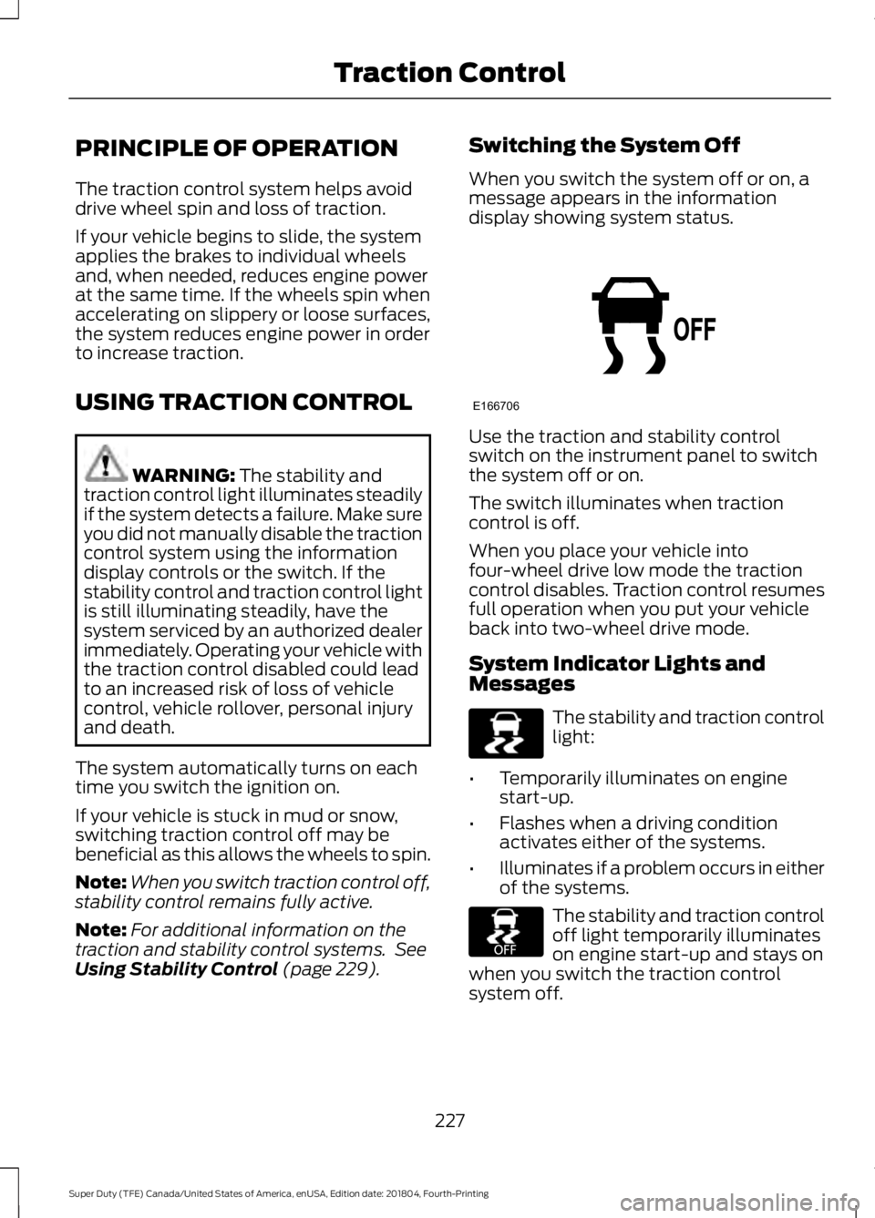
(page 229). Switching the System Off
When you switch the system off or on, a
message appears in the information
display showing system status.
Use the traction and stability control
switch on the instrument panel to switch
the system off or on.
The switch illuminates when traction
control is off.
When you place your vehicle into
four-wheel drive low mode the traction
control disables. Traction control resumes
full operation when you put your vehicle
back into two-wheel drive mode.
System Indicator Lights and
Messages
The stability and traction control
light:
• Temporarily illuminates on engine
start-up.
• Flashes when a driving condition
activates either of the systems.
• Illuminates if a problem occurs in either
of the systems. The stability and traction control
off light temporarily illuminates
on engine start-up and stays on
when you switch the traction control
system off.
227
Super Duty (TFE) Canada/United States of America, enUSA, Edition date: 201804, Fourth-Printing Traction ControlE166706 E225465 E225466
Page 251 of 666
A message displays if something obstructs
the radar signals from the sensor. The
sensor is in the lower grille. The system
cannot detect a vehicle ahead and does
not function when something blocks the
sensor.
Note:
You cannot see the sensor. It is
behind a fascia panel.
Keep the front of your vehicle free of dirt,
metal badges or objects. Vehicle front
protectors and aftermarket lights may also
block the sensor.
Possible Causes and Actions for This Message Displaying: Action
Cause
Clean the grille surface in front of the radar
or remove the object causing the obstruc-
tion.
The surface of the radar is dirty or
obstructed.
Wait a short time. It may take several
minutes for the radar to detect that it is free
from obstruction.
The surface of the radar is clean but the
message remains in the display.
Do not use the system in these conditions
because it may not detect any vehicles
ahead.
Heavy rain or snow is interfering with the
radar signals.
Do not use the system in these conditions
because it may not detect any vehicles
ahead.
Water, snow or ice on the surface of the
road may interfere with the radar signals.
Wait a short time or switch to normal cruise
control.
You are in a desert or remote area with no
other vehicles and no roadside objects.
Due to the nature of radar technology, it is possible to get a blockage warning with no
actual block. A false blocked condition either self clears, or clears after you restart your
vehicle.
Switching to Normal Cruise
Control WARNING: Normal cruise control
will not brake when your vehicle is
approaching slower vehicles. Always be
aware of which mode you have selected
and apply the brakes when necessary. The cruise control indicator light
replaces the adaptive cruise
control indicator light if you
select normal cruise control. The gap
setting does not display, and the system
does not respond to lead vehicles.
Automatic braking remains active to
maintain set speed.
You can change from adaptive cruise
control to normal cruise control through
the information display.
248
Super Duty (TFE) Canada/United States of America, enUSA, Edition date: 201804, Fourth-Printing Cruise Control
(If Equipped)E71340
Page 257 of 666
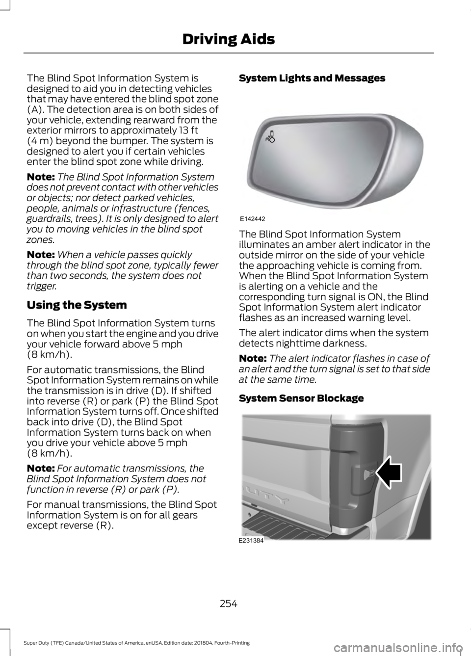
The Blind Spot Information System is
designed to aid you in detecting vehicles
that may have entered the blind spot zone
(A). The detection area is on both sides of
your vehicle, extending rearward from the
exterior mirrors to approximately 13 ft
(4 m) beyond the bumper. The system is
designed to alert you if certain vehicles
enter the blind spot zone while driving.
Note: The Blind Spot Information System
does not prevent contact with other vehicles
or objects; nor detect parked vehicles,
people, animals or infrastructure (fences,
guardrails, trees). It is only designed to alert
you to moving vehicles in the blind spot
zones.
Note: When a vehicle passes quickly
through the blind spot zone, typically fewer
than two seconds, the system does not
trigger.
Using the System
The Blind Spot Information System turns
on when you start the engine and you drive
your vehicle forward above
5 mph
(8 km/h).
For automatic transmissions, the Blind
Spot Information System remains on while
the transmission is in drive (D). If shifted
into reverse (R) or park (P) the Blind Spot
Information System turns off. Once shifted
back into drive (D), the Blind Spot
Information System turns back on when
you drive your vehicle above
5 mph
(8 km/h).
Note: For automatic transmissions, the
Blind Spot Information System does not
function in reverse (R) or park (P).
For manual transmissions, the Blind Spot
Information System is on for all gears
except reverse (R). System Lights and Messages
The Blind Spot Information System
illuminates an amber alert indicator in the
outside mirror on the side of your vehicle
the approaching vehicle is coming from.
When the Blind Spot Information System
is alerting on a vehicle and the
corresponding turn signal is ON, the Blind
Spot Information System alert indicator
flashes as an increased warning level.
The alert indicator dims when the system
detects nighttime darkness.
Note:
The alert indicator flashes in case of
an alert and the turn signal is set to that side
at the same time.
System Sensor Blockage 254
Super Duty (TFE) Canada/United States of America, enUSA, Edition date: 201804, Fourth-Printing Driving AidsE142442 E231384
Page 262 of 666
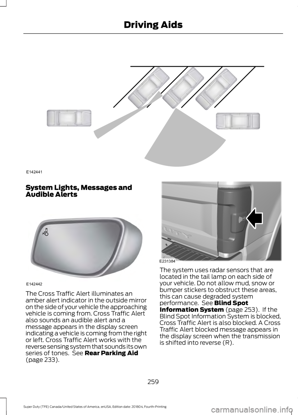
System Lights, Messages and
Audible Alerts
The Cross Traffic Alert illuminates an
amber alert indicator in the outside mirror
on the side of your vehicle the approaching
vehicle is coming from. Cross Traffic Alert
also sounds an audible alert and a
message appears in the display screen
indicating a vehicle is coming from the right
or left. Cross Traffic Alert works with the
reverse sensing system that sounds its own
series of tones. See Rear Parking Aid
(page 233). The system uses radar sensors that are
located in the tail lamp on each side of
your vehicle. Do not allow mud, snow or
bumper stickers to obstruct these areas,
this can cause degraded system
performance. See
Blind Spot
Information System (page 253). If the
Blind Spot Information System is blocked,
Cross Traffic Alert is also blocked. A Cross
Traffic Alert blocked message appears in
the display screen when the transmission
is shifted into reverse (R).
259
Super Duty (TFE) Canada/United States of America, enUSA, Edition date: 201804, Fourth-Printing Driving AidsE142441 E142442 E231384
Page 290 of 666
ESSENTIAL TOWING CHECKS
WARNING: Do not exceed the
maximum vertical load on the tow ball.
Failure to follow this instruction could
result in the loss of control of your
vehicle, personal injury or death.
Follow these guidelines for safe towing:
• Do not tow a trailer until you drive your
vehicle at least
1,000 mi (1,600 km).
• Consult your local motor vehicle laws
for towing a trailer.
• See the instructions included with
towing accessories for the proper
installation and adjustment
specifications.
• Service your vehicle more frequently if
you tow a trailer. See your scheduled
maintenance information.
See
Scheduled Maintenance (page 580).
• If you use a rental trailer, follow the
instructions the rental agency gives
you.
See
Load Limits in the Load Carrying
chapter for load specification terms found
on the tire label and Safety Compliance
label and instructions on calculating your
vehicle's load.
Vehicles with a diesel engine have an
engine braking feature.
See General
Information (page 223).
Remember to account for the trailer
tongue weight as part of your vehicle load
when calculating the total vehicle weight.
Some vehicles will have the ability to
modify trailer towing features. See
General Information
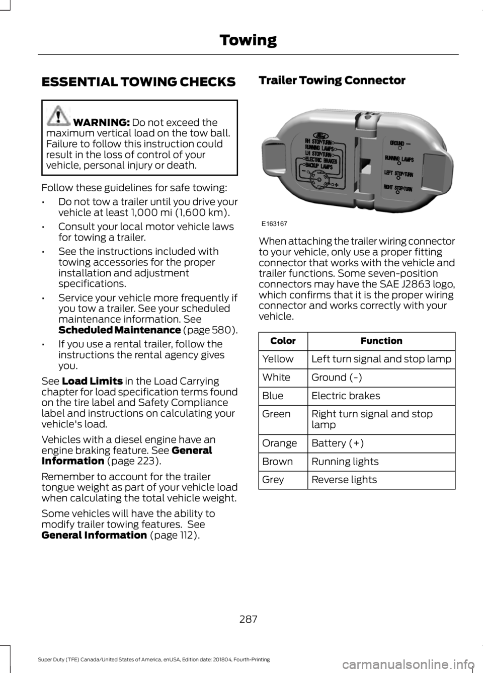
(page 112). Trailer Towing Connector
When attaching the trailer wiring connector
to your vehicle, only use a proper fitting
connector that works with the vehicle and
trailer functions. Some seven-position
connectors may have the SAE J2863 logo,
which confirms that it is the proper wiring
connector and works correctly with your
vehicle.
Function
Color
Left turn signal and stop lamp
Yellow
Ground (-)
White
Electric brakes
Blue
Right turn signal and stop
lamp
Green
Battery (+)
Orange
Running lights
Brown
Reverse lights
Grey
287
Super Duty (TFE) Canada/United States of America, enUSA, Edition date: 201804, Fourth-Printing TowingE163167
Page 295 of 666
Integrated Trailer Brake Controller
(If Equipped)
WARNING: The anti-lock brake
system does not control the trailer
brakes. WARNING:
Use the integrated
trailer brake controller to properly adjust
the trailer brakes and check all
connections before towing a trailer.
Failure to follow this instruction could
result in the loss of control of your
vehicle, personal injury or death.
Note: The integrated Ford brake controller
is compatible with trailers equipped with
electric-actuated drum brakes and
electric-over hydraulic brake systems.
Note: The integrated Ford brake controller
does not control hydraulic surge-style
brakes. When used properly, the trailer brake
controller assists in smooth and effective
trailer braking by powering the trailer
’s
electric or electric-over-hydraulic brakes
with a proportional output based on the
towing vehicle ’s brake pressure.
You can adjust the amount of initial trailer
brake output by selecting one of three
settings through the message center. Ford has tested the trailer brake controller
to be compatible with several major
brands of electric-over-hydraulic trailer
brakes. Contact an authorized dealer for
information on which brands you can use.
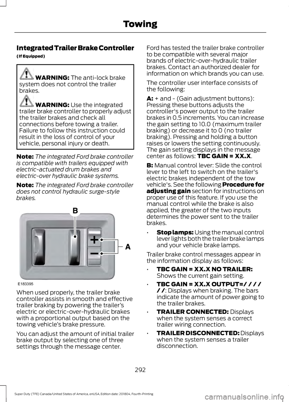
The controller user interface consists of
the following:
A: + and - (Gain adjustment buttons):
Pressing these buttons adjusts the
controller's power output to the trailer
brakes in 0.5 increments. You can increase
the gain setting to 10.0 (maximum trailer
braking) or decrease it to 0 (no trailer
braking). Pressing and holding a button
raises or lowers the setting continuously.
The gain setting displays in the message
center as follows:
TBC GAIN = XX.X.
B:
Manual control lever: Slide the control
lever to the left to switch on the trailer's
electric brakes independent of the tow
vehicle's. See the following Procedure for
adjusting gain section for instructions on
proper use of this feature. If you use the
manual control while the brake is also
applied, the greater of the two inputs
determines the power sent to the trailer
brakes.
• Stop lamps: Using the manual control
lever lights both the trailer brake lamps
and your vehicle brake lamps.
Trailer brake control messages appear in
the information display as follows:
• TBC GAIN = XX.X NO TRAILER:
Shows the current gain setting.
• TBC GAIN = XX.X OUTPUT=/ / / /
/ /
: Displays when braking. The bars
indicate the amount of power going to
the trailer brakes.
• TRAILER CONNECTED:
Displays
when the system senses a correct
trailer wiring connection.
• TRAILER DISCONNECTED: Displays
when the system senses a trailer
disconnection.
292
Super Duty (TFE) Canada/United States of America, enUSA, Edition date: 201804, Fourth-Printing TowingE183395
Page 297 of 666
If this message displays, with no trailer
connected, the problem is with your vehicle
wiring or trailer brake controller. Contact
an authorized dealer.
If the message only displays with a trailer
connected, the problem is with the trailer
wiring. Consult your trailer dealer for
assistance. This can be a short to ground
(such as a chaffed wire), short to voltage
(such as a pulled pin on trailer emergency
breakaway battery) or the trailer brakes
may be drawing too much current.
Points to Remember
Note:
Do not attempt removal of the trailer
brake controller without consulting the
Workshop Manual. Damage to the unit may
result.
• Adjust gain setting before using the
trailer brake controller.
• Adjust gain setting, using the procedure
above, whenever road, weather, trailer
or vehicle loading conditions change
from when the gain was initially set.
• Only use the manual control lever for
proper adjustment of the gain during
trailer setup. Misuse, such as
application during trailer sway, could
cause instability of trailer or tow
vehicle.
• Avoid towing in adverse weather
conditions. The trailer brake controller
does not provide anti-lock control of
the trailer wheels. Trailer wheels can
lock up on slippery surfaces, resulting
in reduced stability of trailer and tow
vehicle.
• The trailer brake controller is equipped
with a feature that reduces output at
vehicle speeds below 11 mph (18 km/h)
so trailer and vehicle braking is not jerky
or harsh. This feature is only active
when applying the brakes using your
vehicle's brake pedal, not the
controller. •
The controller interacts with the brake
control system and powertrain control
system of your vehicle to provide the
best performance on different road
conditions.
• Your vehicle's brake system and the
trailer brake system work
independently of each other. Changing
the gain setting on the controller does
not affect the operation of your
vehicle's brakes.
• When you switch the engine off, the
controller output is disabled and the
display and module shut down.
Trailer Lamps WARNING: Never connect any
trailer lamp wiring to the vehicle's tail
lamp wiring; this may damage the
electrical system resulting in fire. Contact
your authorized dealer as soon as
possible for assistance in proper trailer
tow wiring installation. Additional
electrical equipment may be required.
Trailer lamps are required on most towed
vehicles. Make sure all running lights, brake
lights, turn signals and hazard lights are
working.
Before Towing a Trailer
Practice turning, stopping and backing up
to get the feel of your vehicle-trailer
combination before starting on a trip.
When turning, make wider turns so the
trailer wheels clear curbs and other
obstacles.
294
Super Duty (TFE) Canada/United States of America, enUSA, Edition date: 201804, Fourth-Printing Towing
Page 303 of 666
•
Fuel economy may decrease with lower
temperatures during the first 5–10 mi
(12 –16 km) of driving.
• Driving on flat terrain offers improved
fuel economy as compared to driving
on hilly terrain.
• Transmissions give their best fuel
economy when operated in the top
cruise gear and with steady pressure
on the gas pedal.
• Four-wheel-drive operation (if
equipped) is less fuel efficient than
two-wheel-drive operation.
• Close the windows for high-speed
driving.
DRIVING THROUGH WATER WARNING:
Do not drive through
flowing or deep water as you may lose
control of your vehicle.
Note: Driving through standing water can
cause vehicle damage.
Note: Engine damage can occur if water
enters the air filter.
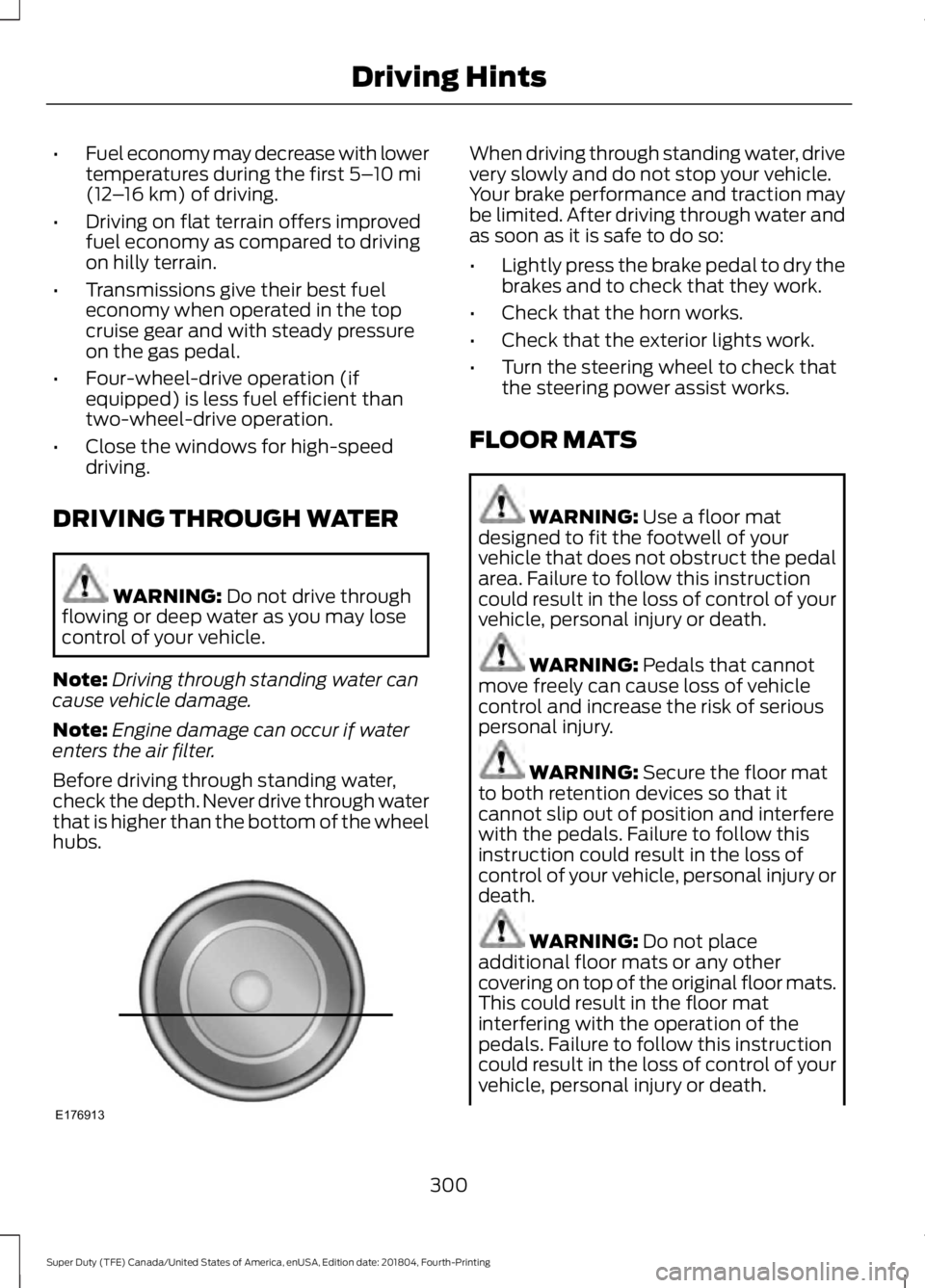
Before driving through standing water,
check the depth. Never drive through water
that is higher than the bottom of the wheel
hubs. When driving through standing water, drive
very slowly and do not stop your vehicle.
Your brake performance and traction may
be limited. After driving through water and
as soon as it is safe to do so:
•
Lightly press the brake pedal to dry the
brakes and to check that they work.
• Check that the horn works.
• Check that the exterior lights work.
• Turn the steering wheel to check that
the steering power assist works.
FLOOR MATS WARNING:
Use a floor mat
designed to fit the footwell of your
vehicle that does not obstruct the pedal
area. Failure to follow this instruction
could result in the loss of control of your
vehicle, personal injury or death. WARNING:
Pedals that cannot
move freely can cause loss of vehicle
control and increase the risk of serious
personal injury. WARNING:
Secure the floor mat
to both retention devices so that it
cannot slip out of position and interfere
with the pedals. Failure to follow this
instruction could result in the loss of
control of your vehicle, personal injury or
death. WARNING:
Do not place
additional floor mats or any other
covering on top of the original floor mats.
This could result in the floor mat
interfering with the operation of the
pedals. Failure to follow this instruction
could result in the loss of control of your
vehicle, personal injury or death.
300
Super Duty (TFE) Canada/United States of America, enUSA, Edition date: 201804, Fourth-Printing Driving HintsE176913