warning light FORD F-250 2019 Repair Manual
[x] Cancel search | Manufacturer: FORD, Model Year: 2019, Model line: F-250, Model: FORD F-250 2019Pages: 666, PDF Size: 13.6 MB
Page 293 of 666
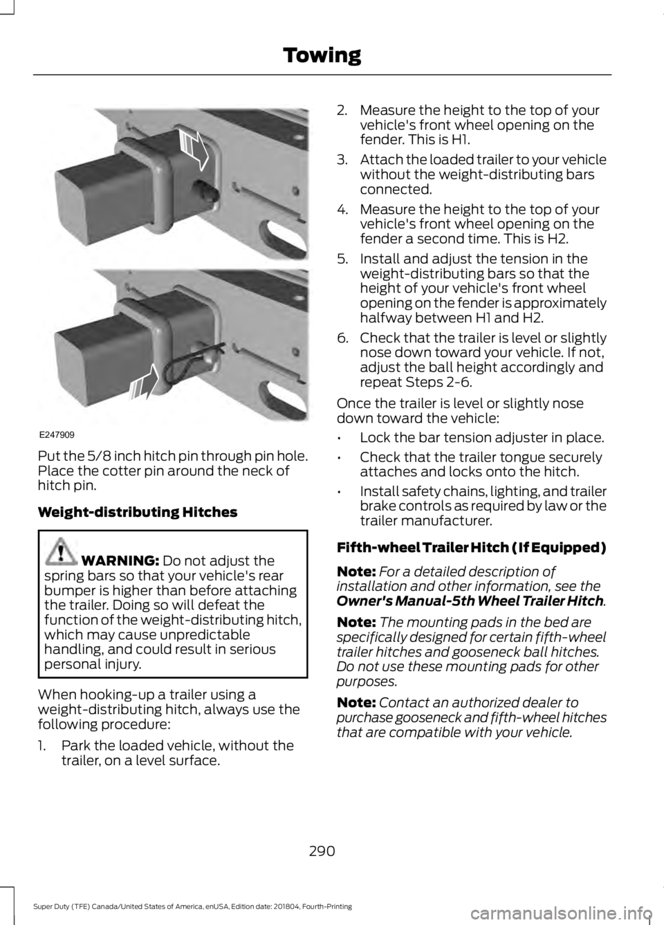
Put the 5/8 inch hitch pin through pin hole.
Place the cotter pin around the neck of
hitch pin.
Weight-distributing Hitches
WARNING: Do not adjust the
spring bars so that your vehicle's rear
bumper is higher than before attaching
the trailer. Doing so will defeat the
function of the weight-distributing hitch,
which may cause unpredictable
handling, and could result in serious
personal injury.
When hooking-up a trailer using a
weight-distributing hitch, always use the
following procedure:
1. Park the loaded vehicle, without the trailer, on a level surface. 2. Measure the height to the top of your
vehicle's front wheel opening on the
fender. This is H1.
3. Attach the loaded trailer to your vehicle
without the weight-distributing bars
connected.
4. Measure the height to the top of your vehicle's front wheel opening on the
fender a second time. This is H2.
5. Install and adjust the tension in the weight-distributing bars so that the
height of your vehicle's front wheel
opening on the fender is approximately
halfway between H1 and H2.
6. Check that the trailer is level or slightly
nose down toward your vehicle. If not,
adjust the ball height accordingly and
repeat Steps 2-6.
Once the trailer is level or slightly nose
down toward the vehicle:
• Lock the bar tension adjuster in place.
• Check that the trailer tongue securely
attaches and locks onto the hitch.
• Install safety chains, lighting, and trailer
brake controls as required by law or the
trailer manufacturer.
Fifth-wheel Trailer Hitch (If Equipped)
Note: For a detailed description of
installation and other information, see the
Owner's Manual-5th Wheel Trailer Hitch.
Note: The mounting pads in the bed are
specifically designed for certain fifth-wheel
trailer hitches and gooseneck ball hitches.
Do not use these mounting pads for other
purposes.
Note: Contact an authorized dealer to
purchase gooseneck and fifth-wheel hitches
that are compatible with your vehicle.
290
Super Duty (TFE) Canada/United States of America, enUSA, Edition date: 201804, Fourth-Printing TowingE247909
Page 295 of 666
Integrated Trailer Brake Controller
(If Equipped)
WARNING: The anti-lock brake
system does not control the trailer
brakes. WARNING:
Use the integrated
trailer brake controller to properly adjust
the trailer brakes and check all
connections before towing a trailer.
Failure to follow this instruction could
result in the loss of control of your
vehicle, personal injury or death.
Note: The integrated Ford brake controller
is compatible with trailers equipped with
electric-actuated drum brakes and
electric-over hydraulic brake systems.
Note: The integrated Ford brake controller
does not control hydraulic surge-style
brakes. When used properly, the trailer brake
controller assists in smooth and effective
trailer braking by powering the trailer
’s
electric or electric-over-hydraulic brakes
with a proportional output based on the
towing vehicle ’s brake pressure.
You can adjust the amount of initial trailer
brake output by selecting one of three
settings through the message center. Ford has tested the trailer brake controller
to be compatible with several major
brands of electric-over-hydraulic trailer
brakes. Contact an authorized dealer for
information on which brands you can use.
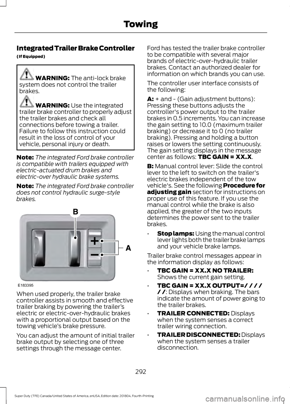
The controller user interface consists of
the following:
A: + and - (Gain adjustment buttons):
Pressing these buttons adjusts the
controller's power output to the trailer
brakes in 0.5 increments. You can increase
the gain setting to 10.0 (maximum trailer
braking) or decrease it to 0 (no trailer
braking). Pressing and holding a button
raises or lowers the setting continuously.
The gain setting displays in the message
center as follows:
TBC GAIN = XX.X.
B:
Manual control lever: Slide the control
lever to the left to switch on the trailer's
electric brakes independent of the tow
vehicle's. See the following Procedure for
adjusting gain section for instructions on
proper use of this feature. If you use the
manual control while the brake is also
applied, the greater of the two inputs
determines the power sent to the trailer
brakes.
• Stop lamps: Using the manual control
lever lights both the trailer brake lamps
and your vehicle brake lamps.
Trailer brake control messages appear in
the information display as follows:
• TBC GAIN = XX.X NO TRAILER:
Shows the current gain setting.
• TBC GAIN = XX.X OUTPUT=/ / / /
/ /
: Displays when braking. The bars
indicate the amount of power going to
the trailer brakes.
• TRAILER CONNECTED:
Displays
when the system senses a correct
trailer wiring connection.
• TRAILER DISCONNECTED: Displays
when the system senses a trailer
disconnection.
292
Super Duty (TFE) Canada/United States of America, enUSA, Edition date: 201804, Fourth-Printing TowingE183395
Page 297 of 666
If this message displays, with no trailer
connected, the problem is with your vehicle
wiring or trailer brake controller. Contact
an authorized dealer.
If the message only displays with a trailer
connected, the problem is with the trailer
wiring. Consult your trailer dealer for
assistance. This can be a short to ground
(such as a chaffed wire), short to voltage
(such as a pulled pin on trailer emergency
breakaway battery) or the trailer brakes
may be drawing too much current.
Points to Remember
Note:
Do not attempt removal of the trailer
brake controller without consulting the
Workshop Manual. Damage to the unit may
result.
• Adjust gain setting before using the
trailer brake controller.
• Adjust gain setting, using the procedure
above, whenever road, weather, trailer
or vehicle loading conditions change
from when the gain was initially set.
• Only use the manual control lever for
proper adjustment of the gain during
trailer setup. Misuse, such as
application during trailer sway, could
cause instability of trailer or tow
vehicle.
• Avoid towing in adverse weather
conditions. The trailer brake controller
does not provide anti-lock control of
the trailer wheels. Trailer wheels can
lock up on slippery surfaces, resulting
in reduced stability of trailer and tow
vehicle.
• The trailer brake controller is equipped
with a feature that reduces output at
vehicle speeds below 11 mph (18 km/h)
so trailer and vehicle braking is not jerky
or harsh. This feature is only active
when applying the brakes using your
vehicle's brake pedal, not the
controller. •
The controller interacts with the brake
control system and powertrain control
system of your vehicle to provide the
best performance on different road
conditions.
• Your vehicle's brake system and the
trailer brake system work
independently of each other. Changing
the gain setting on the controller does
not affect the operation of your
vehicle's brakes.
• When you switch the engine off, the
controller output is disabled and the
display and module shut down.
Trailer Lamps WARNING: Never connect any
trailer lamp wiring to the vehicle's tail
lamp wiring; this may damage the
electrical system resulting in fire. Contact
your authorized dealer as soon as
possible for assistance in proper trailer
tow wiring installation. Additional
electrical equipment may be required.
Trailer lamps are required on most towed
vehicles. Make sure all running lights, brake
lights, turn signals and hazard lights are
working.
Before Towing a Trailer
Practice turning, stopping and backing up
to get the feel of your vehicle-trailer
combination before starting on a trip.
When turning, make wider turns so the
trailer wheels clear curbs and other
obstacles.
294
Super Duty (TFE) Canada/United States of America, enUSA, Edition date: 201804, Fourth-Printing Towing
Page 303 of 666
•
Fuel economy may decrease with lower
temperatures during the first 5–10 mi
(12 –16 km) of driving.
• Driving on flat terrain offers improved
fuel economy as compared to driving
on hilly terrain.
• Transmissions give their best fuel
economy when operated in the top
cruise gear and with steady pressure
on the gas pedal.
• Four-wheel-drive operation (if
equipped) is less fuel efficient than
two-wheel-drive operation.
• Close the windows for high-speed
driving.
DRIVING THROUGH WATER WARNING:
Do not drive through
flowing or deep water as you may lose
control of your vehicle.
Note: Driving through standing water can
cause vehicle damage.
Note: Engine damage can occur if water
enters the air filter.
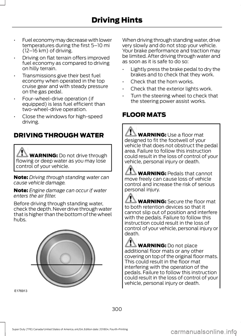
Before driving through standing water,
check the depth. Never drive through water
that is higher than the bottom of the wheel
hubs. When driving through standing water, drive
very slowly and do not stop your vehicle.
Your brake performance and traction may
be limited. After driving through water and
as soon as it is safe to do so:
•
Lightly press the brake pedal to dry the
brakes and to check that they work.
• Check that the horn works.
• Check that the exterior lights work.
• Turn the steering wheel to check that
the steering power assist works.
FLOOR MATS WARNING:
Use a floor mat
designed to fit the footwell of your
vehicle that does not obstruct the pedal
area. Failure to follow this instruction
could result in the loss of control of your
vehicle, personal injury or death. WARNING:
Pedals that cannot
move freely can cause loss of vehicle
control and increase the risk of serious
personal injury. WARNING:
Secure the floor mat
to both retention devices so that it
cannot slip out of position and interfere
with the pedals. Failure to follow this
instruction could result in the loss of
control of your vehicle, personal injury or
death. WARNING:
Do not place
additional floor mats or any other
covering on top of the original floor mats.
This could result in the floor mat
interfering with the operation of the
pedals. Failure to follow this instruction
could result in the loss of control of your
vehicle, personal injury or death.
300
Super Duty (TFE) Canada/United States of America, enUSA, Edition date: 201804, Fourth-Printing Driving HintsE176913
Page 304 of 666
WARNING: Always make sure that
objects cannot fall into the driver foot
well while your vehicle is moving. Objects
that are loose can become trapped
under the pedals causing a loss of
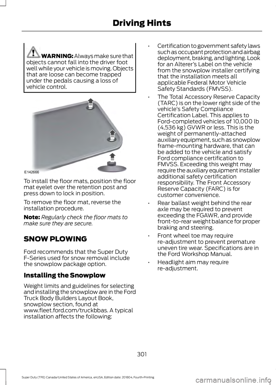
vehicle control. To install the floor mats, position the floor
mat eyelet over the retention post and
press down to lock in position.
To remove the floor mat, reverse the
installation procedure.
Note:
Regularly check the floor mats to
make sure they are secure.
SNOW PLOWING
Ford recommends that the Super Duty
F-Series used for snow removal include
the snowplow package option.
Installing the Snowplow
Weight limits and guidelines for selecting
and installing the snowplow are in the Ford
Truck Body Builders Layout Book,
snowplow section, found at
www.fleet.ford.com/truckbbas. A typical
installation affects the following: •
Certification to government safety laws
such as occupant protection and airbag
deployment, braking, and lighting. Look
for an Alterer ’s Label on the vehicle
from the snowplow installer certifying
that the installation meets all
applicable Federal Motor Vehicle
Safety Standards (FMVSS).
• The Total Accessory Reserve Capacity
(TARC) is on the lower right side of the
vehicle ’s Safety Compliance
Certification Label. This applies to
Ford-completed vehicles of 10,000 lb
(4,536 kg) GVWR or less. This is the
weight of permanently-attached
auxiliary equipment, such as snowplow
frame-mounting hardware, that can
be added to the vehicle and satisfy
Ford compliance certification to
FMVSS. Exceeding this weight may
require the auxiliary equipment installer
additional safety certification
responsibility. The Front Accessory
Reserve Capacity (FARC) is for
customer convenience.
• Rear ballast weight behind the rear
axle may be required to prevent
exceeding the FGAWR, and provide
front-to-rear weight balance for proper
braking and steering.
• Front wheel toe may require
re-adjustment to prevent premature
uneven tire wear. Specifications are in
the Ford Workshop Manual.
• Headlight aim may require
re-adjustment.
301
Super Duty (TFE) Canada/United States of America, enUSA, Edition date: 201804, Fourth-Printing Driving HintsE142666
Page 306 of 666
Engine temperature while plowing
When driving with a plow, your engine may
run at a higher temperature than normal
because the attached snowplow blade will
restrict airflow to the radiator.
•
If you are driving more than 15 mi
(24 km) at temperatures above
freezing, angle the plow blade either
full left or full right to provide
maximum airflow to the radiator.
• If you are driving less than
15 mi
(24 km) at speeds up to 45 mph
(72 km/h) in cold weather, you will not
need to worry about blade position to
provide maximum airflow.
Transmission operation while
plowing WARNING: Do not spin the wheels
at over
34 mph (55 km/h). The tires may
fail and injure a passenger or bystander.
• Shift transfer case to
4L (4WD Low)
when plowing in small areas at speeds
below
5 mph (8 km/h).
• Shift transfer case to
4H (4WD High)
when plowing larger areas or light snow
at higher speeds. Do not exceed 15 mph
(24 km/h)
.
• Do not shift the transmission from a
forward gear to
R (Reverse) until the
engine is at idle and the wheels have
stopped.
303
Super Duty (TFE) Canada/United States of America, enUSA, Edition date: 201804, Fourth-Printing Driving Hints
Page 309 of 666
The fuel pump shutoff stops the flow of
fuel to the engine in the event of a
moderate to severe crash. Not every
impact causes a shutoff.
Should your vehicle shut off after a crash,
you may restart your vehicle.
If your vehicle has a key system:
1. Switch off the ignition.
2. Switch to start position.
3. Switch off the ignition.
4.
Switch on the ignition to re-enable the
fuel pump.
5. If the vehicle does not start, repeat steps 1 through 4.
If your vehicle has a push button start
system:
1. Press START/STOP to switch off your
vehicle.
2. Press the brake pedal and START/STOP
to switch on your
vehicle.
3. Remove your foot from the brake pedal
and press
START/STOP to switch off
your vehicle.
4. You can attempt to start the vehicle by pressing the brake pedal and
START/STOP
, or press START/STOP
without pressing the brake pedal.
5. If the vehicle does not start, repeat steps 1 through 4.
JUMP STARTING THE VEHICLE WARNING:
Batteries normally
produce explosive gases which can
cause personal injury. Therefore, do not
allow flames, sparks or lighted
substances to come near the battery.
When working near the battery, always
shield your face and protect your eyes.
Always provide correct ventilation. WARNING:
Keep batteries out of
reach of children. Batteries contain
sulfuric acid. Avoid contact with skin,
eyes or clothing. Shield your eyes when
working near the battery to protect
against possible splashing of acid
solution. In case of acid contact with skin
or eyes, flush immediately with water for
a minimum of 15 minutes and get prompt
medical attention. If acid is swallowed,
call a physician immediately. WARNING:
Use only adequately
sized cables with insulated clamps.
Preparing Your Vehicle
Do not attempt to push-start your
automatic transmission vehicle.
Note: Attempting to push-start a vehicle
with an automatic transmission may cause
transmission damage.
Note: Use only a 12-volt supply to start your
vehicle.
Note: Do not disconnect the battery of the
disabled vehicle as this could damage the
vehicle electrical system.
Park the booster vehicle close to the hood
of the disabled vehicle, making sure the
two vehicles do not touch.
Connecting the Jumper Cables WARNING:
Do not attach the
cables to fuel lines, engine rocker covers,
the intake manifold or electrical
components as grounding points. Stay
clear of moving parts. To avoid reverse
polarity connections, make sure that you
correctly identify the positive (+) and
negative (-) terminals on both the
disabled and booster vehicles before
connecting the cables.
306
Super Duty (TFE) Canada/United States of America, enUSA, Edition date: 201804, Fourth-Printing Roadside Emergencies
Page 342 of 666
Action and description
Message
Press and hold the OK
button until the instrument
cluster displays the
following message.
Hold OK to
Reset
Reset Successful
When the oil change indic-
ator resets the instrument
cluster displays 100%.
Remaining Life
{00}%
If the instrument cluster
displays one of the following
messages, repeat the
process.
Not Reset
Reset Cancelled
ENGINE COOLANT CHECK -
6.2L/6.8L WARNING:
Do not remove the
coolant reservoir cap when the engine is
on or the cooling system is hot. Wait 10
minutes for the cooling system to cool
down. Cover the coolant reservoir cap
with a thick cloth to prevent the
possibility of scalding and slowly remove
the cap. Failure to follow this instruction
could result in personal injury. WARNING:
Do not put coolant in
the windshield washer reservoir. If
sprayed on the windshield, coolant could
make it difficult to see through the
windshield. WARNING:
To reduce the risk of
personal injury, make sure the engine is
cool before unscrewing the coolant
pressure relief cap. The cooling system
is under pressure. Steam and hot liquid
can come out forcefully when you loosen
the cap slightly. WARNING:
Do not add coolant
further than the MAX mark.
When the engine is cold, check the
concentration and level of the coolant at
the intervals listed in the scheduled
maintenance information. See Scheduled
Maintenance
(page 580).
Note: Make sure that the coolant level is
between the
MIN and the MAX marks on
the coolant reservoir.
Note: Coolant expands when it is hot. The
level may extend beyond the
MAX mark.
Maintain coolant concentration within
48% to 50%, which equates to a freeze
point between -30°F (-34°C) and -34°F
(-37°C). Coolant concentration should be
checked using a refractometer. We
recommend Robinair® Coolant and
Battery Refractometer 75240 (Rotunda
tool part number: ROB75240). We do not
recommend the use of hydrometers or
coolant test strips for measuring coolant
concentration.
Note: Automotive fluids are not
interchangeable. Do not use coolant or
windshield washer fluid outside of its
specified function and vehicle location.
Note: Do not use stop leak pellets, cooling
system sealants, or additives as they can
cause damage to the engine cooling or
heating systems. Resulting component
damage may not be covered by the vehicle
Warranty.
339
Super Duty (TFE) Canada/United States of America, enUSA, Edition date: 201804, Fourth-Printing Maintenance
Page 346 of 666
ENGINE COOLANT CHECK -
6.7L DIESEL
WARNING: Do not remove the
coolant reservoir cap when the engine is
on or the cooling system is hot. Wait 10
minutes for the cooling system to cool
down. Cover the coolant reservoir cap
with a thick cloth to prevent the
possibility of scalding and slowly remove
the cap. Failure to follow this instruction
could result in personal injury. WARNING:
Do not put coolant in
the windshield washer reservoir. If
sprayed on the windshield, coolant could
make it difficult to see through the
windshield. WARNING:
To reduce the risk of
personal injury, make sure the engine is
cool before unscrewing the coolant
pressure relief cap. The cooling system
is under pressure. Steam and hot liquid
can come out forcefully when you loosen
the cap slightly. WARNING:
Do not add coolant
further than the MAX mark.
When the engine is cold, check the
concentration and level of the coolant at
the intervals listed in the scheduled
maintenance information. See Scheduled
Maintenance
(page 580).
Note: Make sure that the coolant level is
between the
MIN and MAX marks on the
coolant reservoir.
Note: Coolant expands when it is hot. The
level may extend beyond the
MAX mark. Maintain coolant concentration within
48% to 50%, which equates to a freeze
point between -30°F (-34°C) and -34°F
(-37°C). Check the coolant concentration
using a refractometer. We do not
recommend the use of hydrometers or
coolant test strips for measuring coolant
concentration.
Adding Coolant
WARNING:
Do not add engine
coolant when the engine is hot. Failure
to follow this instruction could result in
personal injury. WARNING:
Do not remove the
coolant reservoir cap when the engine is
on or the cooling system is hot. Wait 10
minutes for the cooling system to cool
down. Cover the coolant reservoir cap
with a thick cloth to prevent the
possibility of scalding and slowly remove
the cap. Failure to follow this instruction
could result in personal injury.
Note: Automotive fluids are not
interchangeable. Do not use coolant or
windshield washer fluid outside of its
specified function and vehicle location.
Note: Do not use stop leak pellets, cooling
system sealants, or additives as they can
cause damage to the engine cooling or
heating systems. Resulting component
damage may not be covered by the vehicle
Warranty.
343
Super Duty (TFE) Canada/United States of America, enUSA, Edition date: 201804, Fourth-Printing Maintenance
Page 354 of 666
4.
While the engine idles, turn the steering
wheel left and right several times.
5. Switch the engine off.
6. Recheck the fluid level in the reservoir. Do not add fluid if the level is between
the MIN and MAX range.
7. If the fluid is low, add fluid in small amounts, continuously checking the
level until it is between the MIN and
MAX range. For proper fluid type, See
Capacities and Specifications (page
419). Be sure to put the cap back on the
reservoir.
WASHER FLUID CHECK WARNING:
If you operate your
vehicle in temperatures below 40°F
(5°C), use washer fluid with antifreeze
protection. Failure to use washer fluid
with antifreeze protection in cold
weather could result in impaired
windshield vision and increase the risk
of injury or accident.
Add fluid to fill the reservoir if the level is
low. Only use a washer fluid that meets
Ford specifications. See
Capacities and
Specifications (page 419).
State or local regulations on volatile
organic compounds may restrict the use
of methanol, a common windshield washer
antifreeze additive. Washer fluids
containing non-methanol antifreeze
agents should be used only if they provide
cold weather protection without damaging
the vehicle ’s paint finish, wiper blades or
washer system. DRAINING THE FUEL FILTER
WATER TRAP - 6.7L DIESEL WARNING:
Do not dispose of fuel
in the household refuse or the public
sewage system. Use an authorized waste
disposal facility.
Your vehicle has a diesel fuel conditioner
module. The module is mounted between
the outboard side of the fuel tank and the
frame rail.
Note: The module is at the front of the fuel
tank or at the front of the aft-axle fuel tank
on some models. You should drain water from the
module assembly whenever the
warning light illuminates or a
message appears in the information
display advising you to drain the water
separator. This occurs when approximately
6.76 fl oz (200 ml)
of water accumulates
in the module. If you allow the water level
to exceed this level, the water may pass
through to the engine and may cause fuel
injection equipment damage.
Filter Location
Use the tables below to find the location
of your filter.
351
Super Duty (TFE) Canada/United States of America, enUSA, Edition date: 201804, Fourth-Printing Maintenance