tailgate FORD F-250 2020 User Guide
[x] Cancel search | Manufacturer: FORD, Model Year: 2020, Model line: F-250, Model: FORD F-250 2020Pages: 631, PDF Size: 9.62 MB
Page 94 of 631
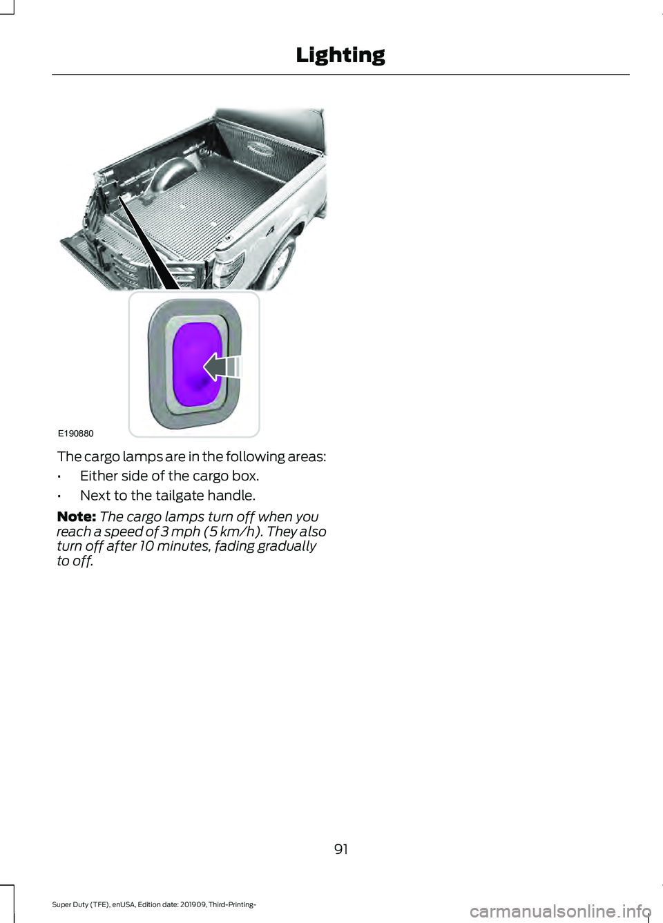
The cargo lamps are in the following areas:
•
Either side of the cargo box.
• Next to the tailgate handle.
Note: The cargo lamps turn off when you
reach a speed of 3 mph (5 km/h). They also
turn off after 10 minutes, fading gradually
to off.
91
Super Duty (TFE), enUSA, Edition date: 201909, Third-Printing- LightingE190880
Page 110 of 631
Powertrain Malfunction/Reduced
Power/Electronic Throttle Control
Illuminates when a powertrain
or a 4WD fault has been
detected. Have your vehicle
checked as soon as possible.
Service Engine Soon Illuminates when you switch the
ignition on prior to engine start
to check the bulb and to indicate
whether your vehicle is ready for Inspection
and Maintenance (I/M) testing.
Normally, it illuminates until the engine is
cranked and automatically turns off if no
malfunctions are present. However, if after
15 seconds it flashes eight times, this
indicates that your vehicle is not ready for
Inspection and Maintenance (I/M) testing.
See Emission Law (page 188).
If it illuminates when the engine is running
this indicates a malfunction. The On Board
Diagnostics system has detected a
malfunction of the vehicle emission control
system.
If it flashes, engine misfire may be
occurring. Increased exhaust gas
temperatures could damage the catalytic
converter or other vehicle components.
Drive in a moderate fashion, avoid heavy
acceleration and deceleration, and have
your vehicle checked immediately.
Stability Control Illuminates when the system is
active. If it remains illuminated
or does not illuminate when you
switch the ignition on, this indicates a
malfunction. During a malfunction, the
system switches off. Have the system
checked immediately. See
Using
Stability Control (page 223). Stability Control Off Illuminates when you switch the
system off. It goes out when you
switch the system back on or
when you switch the ignition off.
See Using Stability Control (page 223).
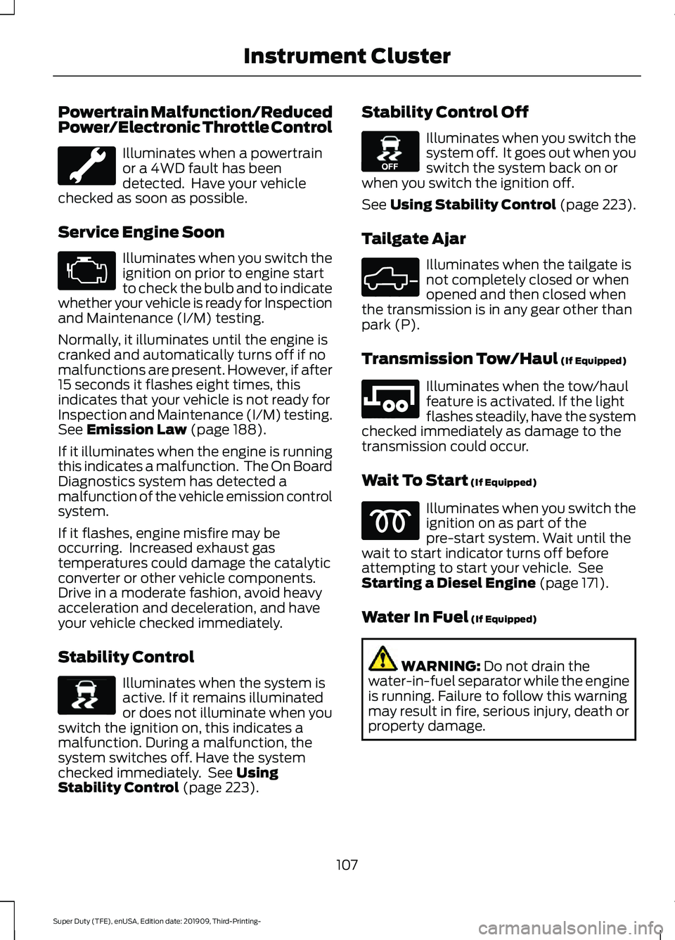
Tailgate Ajar Illuminates when the tailgate is
not completely closed or when
opened and then closed when
the transmission is in any gear other than
park (P).
Transmission Tow/Haul
(If Equipped) Illuminates when the tow/haul
feature is activated. If the light
flashes steadily, have the system
checked immediately as damage to the
transmission could occur.
Wait To Start
(If Equipped) Illuminates when you switch the
ignition on as part of the
pre-start system. Wait until the
wait to start indicator turns off before
attempting to start your vehicle. See
Starting a Diesel Engine
(page 171).
Water In Fuel
(If Equipped) WARNING:
Do not drain the
water-in-fuel separator while the engine
is running. Failure to follow this warning
may result in fire, serious injury, death or
property damage.
107
Super Duty (TFE), enUSA, Edition date: 201909, Third-Printing- Instrument Cluster E138639 E130458 E324523 E246592
Page 137 of 631
Remote Start
Action
Message
A reminder to apply the brake and push the gearshift buttonto drive your vehicle after a remote start.
To Drive: Press Brake
and Gear Shift Button
Seats Action
Message
A reminder that memory seats are not available while driving.
Memory Recall Not
Permitted While Driving
Shows where you have saved your memory setting.
Memory {0} Saved
Starting System Action
Message
A reminder to apply the brake when starting your vehicle .
To START Press Brake
The starter has exceeded its cranking time in attempting tostart your vehicle.
Cranking Time Exceeded
The starter is attempting to start your vehicle.
Engine Start Pending
Please Wait
The system has cancelled the pending start.
Pending Start Cancelled
Tailgate Action
Message
The tailgate is not completely closed.
Tailgate Ajar
134
Super Duty (TFE), enUSA, Edition date: 201909, Third-Printing- Information Displays
Page 232 of 631

The coverage area is up to 6 ft (1.8 m) from
the rear bumper. The coverage area could
decrease at the outer corners of the
bumper.
The system detects certain objects while
the transmission is in reverse (R):
•
Your vehicle is moving toward a
stationary object at a speed of 3 mph
(5 km/h) or less.
• Your vehicle is not moving, but a
moving object is approaching the rear
of your vehicle at a speed of
3 mph
(5 km/h) or less.
• Your vehicle is moving at a speed of
less than 3 mph (5 km/h) and a moving
object is approaching the rear of your
vehicle at a speed of less than
3 mph
(5 km/h).
The system provides audio warnings only
when your vehicle is moving or when your
vehicle is stationary, and the detected
obstacle is less than
12 in (30 cm) away
from the bumper.
Obstacle Distance Indicator
The system provides obstacle distance
indication through the display screen. See
Rear View Camera
(page 229). REAR VIEW CAMERA WARNING:
The rear view camera
system is a reverse aid supplement
device that still requires the driver to use
it in conjunction with the interior and
exterior mirrors for maximum coverage. WARNING:
Objects that are close
to either corner of the bumper or under
the bumper, might not be seen on the
screen due to the limited coverage of the
camera system. WARNING:
Reverse your vehicle
as slow as possible, higher speeds may
limit your reaction time to stop your
vehicle. WARNING:
Use caution when the
tailgate is ajar. If the tailgate is ajar, the
camera will be out of position and the
video image may be incorrect. All
guidelines disappear when the tailgate
is ajar. Some vehicles may not come
equipped with guidelines. WARNING:
Use caution when
turning camera features on or off when
the transmission is not in park (P). Make
sure your vehicle is not moving.
The rear view camera system displays
what is behind your vehicle when you shift
the transmission into reverse (R).
During operation, lines appear in the
display that represents the path of your
vehicle and proximity to objects behind it.
229
Super Duty (TFE), enUSA, Edition date: 201909, Third-Printing- Parking Aids
(If Equipped)E231381
Page 233 of 631
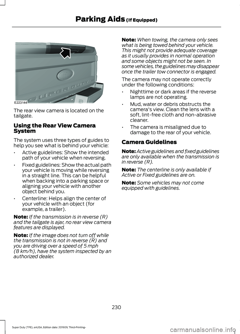
The rear view camera is located on the
tailgate.
Using the Rear View Camera
System
The system uses three types of guides to
help you see what is behind your vehicle:
•
Active guidelines: Show the intended
path of your vehicle when reversing.
• Fixed guidelines: Show the actual path
your vehicle is moving while reversing
in a straight line. This can be helpful
when backing into a parking space or
aligning your vehicle with another
object behind you.
• Centerline: Helps align the center of
your vehicle with an object (for
example, a trailer).
Note: If the transmission is in reverse (R)
and the tailgate is ajar, no rear view camera
features are displayed.
Note: If the image does not turn off while
the transmission is not in reverse (R) and
you are driving over a speed of 5 mph
(8 km/h), have the system inspected by an
authorized dealer. Note:
When towing, the camera only sees
what is being towed behind your vehicle.
This might not provide adequate coverage
as it usually provides in normal operation
and some objects might not be seen. In
some vehicles, the guidelines may disappear
once the trailer tow connector is engaged.
The camera may not operate correctly
under the following conditions:
• Nighttime or dark areas if the reverse
lamps are not operating.
• Mud, water or debris obstructs the
camera's view. Clean the lens with a
soft, lint-free cloth and non-abrasive
cleaner.
• The camera is misaligned due to
damage to the rear of your vehicle.
Camera Guidelines
Note: Active guidelines and fixed guidelines
are only available when the transmission is
in reverse (R).
Note: The centerline is only available if
Active or Fixed guidelines are on.
Note: Some vehicles may not come
equipped with guidelines.
230
Super Duty (TFE), enUSA, Edition date: 201909, Third-Printing- Parking Aids
(If Equipped)E223144
Page 272 of 631
- 1200 = - 240 pounds. No, you do
not have enough cargo capacity
to carry that much weight. In
metric units, the calculation would
be: 635 kilograms - (2 x 99
kilograms) - (12 x 45 kilograms) =
635 - 198 - 540 = -103 kilograms.
You will need to reduce the load
weight by at least 240 pounds
(104 kilograms). If you remove
three 100-pound (45-kilogram)
cement bags, then the load
calculation would be:1400 - (2 x
220) - (9 x 100) = 1400 - 440 -
900 = 60 pounds. Now you have
the load capacity to transport the
cement and your friend home. In
metric units, the calculation would
be: 635 kilograms - (2 x 99
kilograms) - (9 x 45 kilograms) =
635 - 198 - 405 = 32 kilograms.
The above calculations also
assume that the loads are
positioned in your vehicle in a
manner that does not overload
the front or the rear gross axle
weight rating specified for your
vehicle on the Safety Compliance
Certification label.
Special Loading Instructions
for Owners of Pick-up Trucks
and Utility-type Vehicles
WARNING: When loading
the roof racks, we recommend
you evenly distribute the load,
as well as maintain a low center
of gravity. Loaded vehicles, with
higher centers of gravity, may handle differently than unloaded
vehicles. Take extra precautions,
such as slower speeds and
increased stopping distance,
when driving a heavily loaded
vehicle.
BED RAMPS
(IF EQUIPPED) WARNING:
When sliding the ramp
up or down, take care not to get your
fingers or hands caught in the
mechanism. Failure to follow this
instruction could result in personal injury. WARNING:
Make sure that you
correctly install the ramp to the tailgate
plate. Failure to follow this instruction
could result in personal injury. WARNING:
Do not step or sit on
the ramp when it is in the stowed
position. Failure to follow this instruction
could result in personal injury. WARNING:
Only install the ramp
within the prescribed ramp angles.
Failure to follow this instruction could
result in personal injury.
Note: The ramp maximum capacity is
800 lb (363 kg)
.
Note: Verify the ramp is on stable ground
before usage.
Note: For loading and unloading
equipment, your ramp should be set
between 10 degrees upward and 26 degrees
downward to avoid damage to the ramp
claw and tailgate plate.
Note: When using your vehicle for off-road
operation, remove the bed ramps from the
vehicle and store them in a safe location
away from your vehicle.
269
Super Duty (TFE), enUSA, Edition date: 201909, Third-Printing- Load Carrying
Page 273 of 631
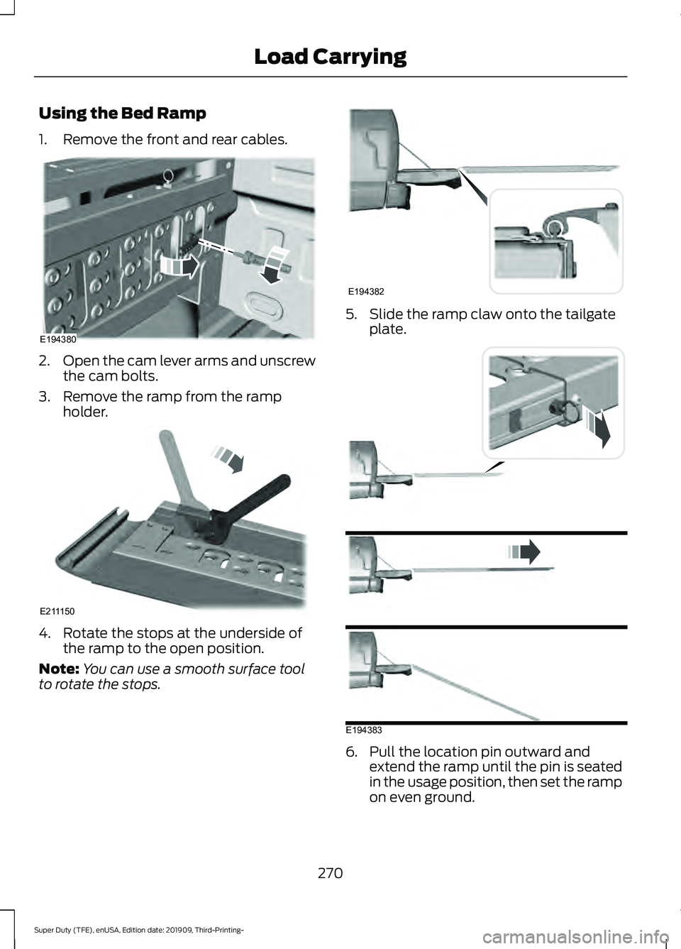
Using the Bed Ramp
1. Remove the front and rear cables.
2.
Open the cam lever arms and unscrew
the cam bolts.
3. Remove the ramp from the ramp holder. 4. Rotate the stops at the underside of
the ramp to the open position.
Note: You can use a smooth surface tool
to rotate the stops. 5. Slide the ramp claw onto the tailgate
plate. 6. Pull the location pin outward and
extend the ramp until the pin is seated
in the usage position, then set the ramp
on even ground.
270
Super Duty (TFE), enUSA, Edition date: 201909, Third-Printing- Load CarryingE194380 E211150 E194382 E194383
Page 274 of 631
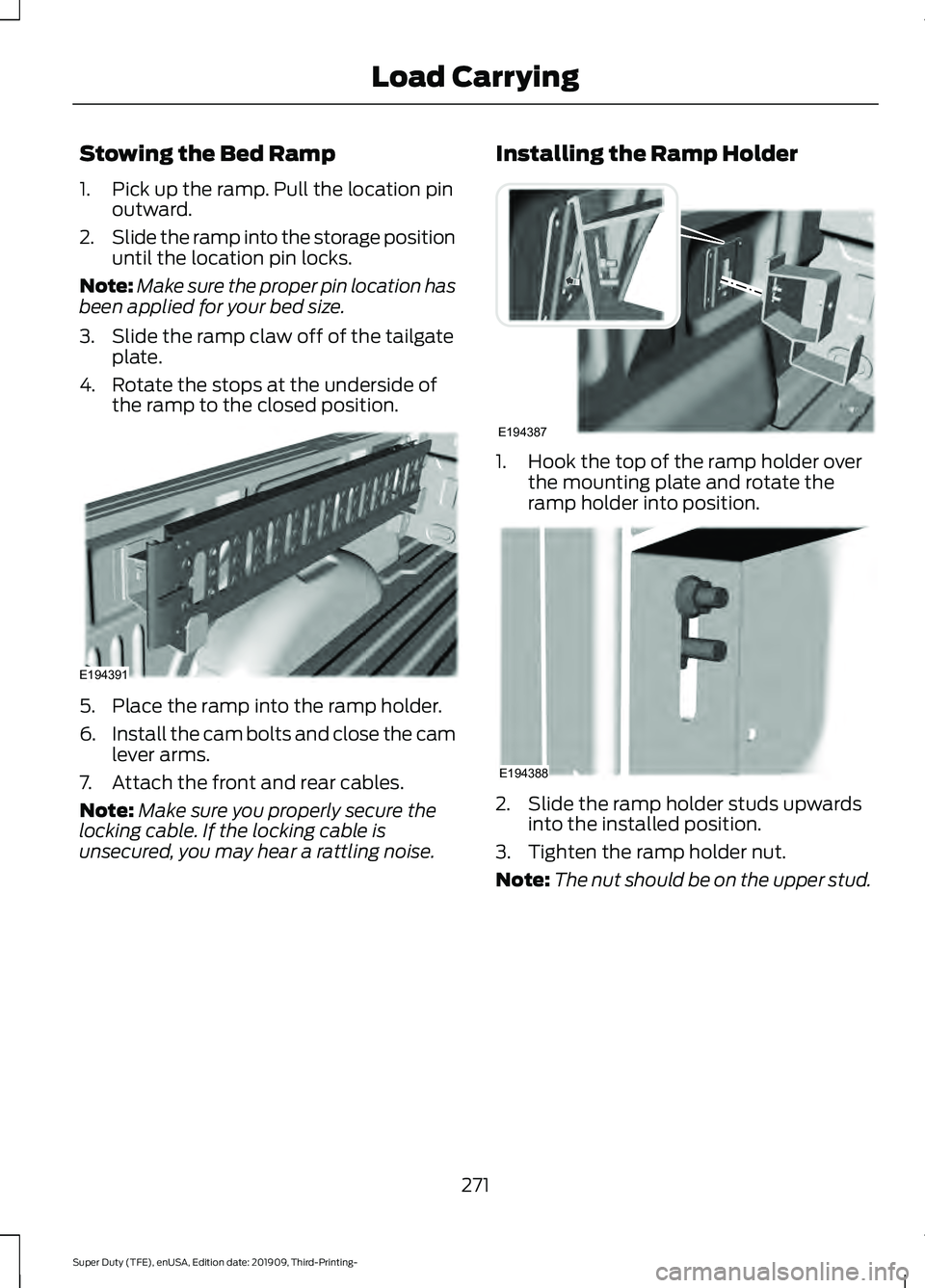
Stowing the Bed Ramp
1. Pick up the ramp. Pull the location pin
outward.
2. Slide the ramp into the storage position
until the location pin locks.
Note: Make sure the proper pin location has
been applied for your bed size.
3. Slide the ramp claw off of the tailgate plate.
4. Rotate the stops at the underside of the ramp to the closed position. 5. Place the ramp into the ramp holder.
6.
Install the cam bolts and close the cam
lever arms.
7. Attach the front and rear cables.
Note: Make sure you properly secure the
locking cable. If the locking cable is
unsecured, you may hear a rattling noise. Installing the Ramp Holder 1. Hook the top of the ramp holder over
the mounting plate and rotate the
ramp holder into position. 2. Slide the ramp holder studs upwards
into the installed position.
3. Tighten the ramp holder nut.
Note: The nut should be on the upper stud.
271
Super Duty (TFE), enUSA, Edition date: 201909, Third-Printing- Load CarryingE194391 E194387 E194388
Page 280 of 631
Note:
When rounding in inches, round
upward if the measured length is a quarter
inch or greater. Round downward if the
measured length is less than a quarter inch.
For example, 12.25 in (31.11 cm) would be
rounded up to 12.50 in (31.75 cm). 12.13 in
(30.8 cm) would be rounded down to
12.00 in (30.48 cm).
Note: When rounding in centimeters, round
to the nearest whole centimeter. If the
measurement is less than
0.2 in (0.5 cm)
round downward. If the measurement is
more than or equal to 0.2 in (0.5 cm) round
upward. For example, 11.9 in (30.3 cm)
would be rounded down to
11.8 in (30 cm).
12.0 in (30.5 cm) would be rounded up to
12.2 in (31 cm).
Note: Use consistent metric or imperial
units as required by your country or vehicle.
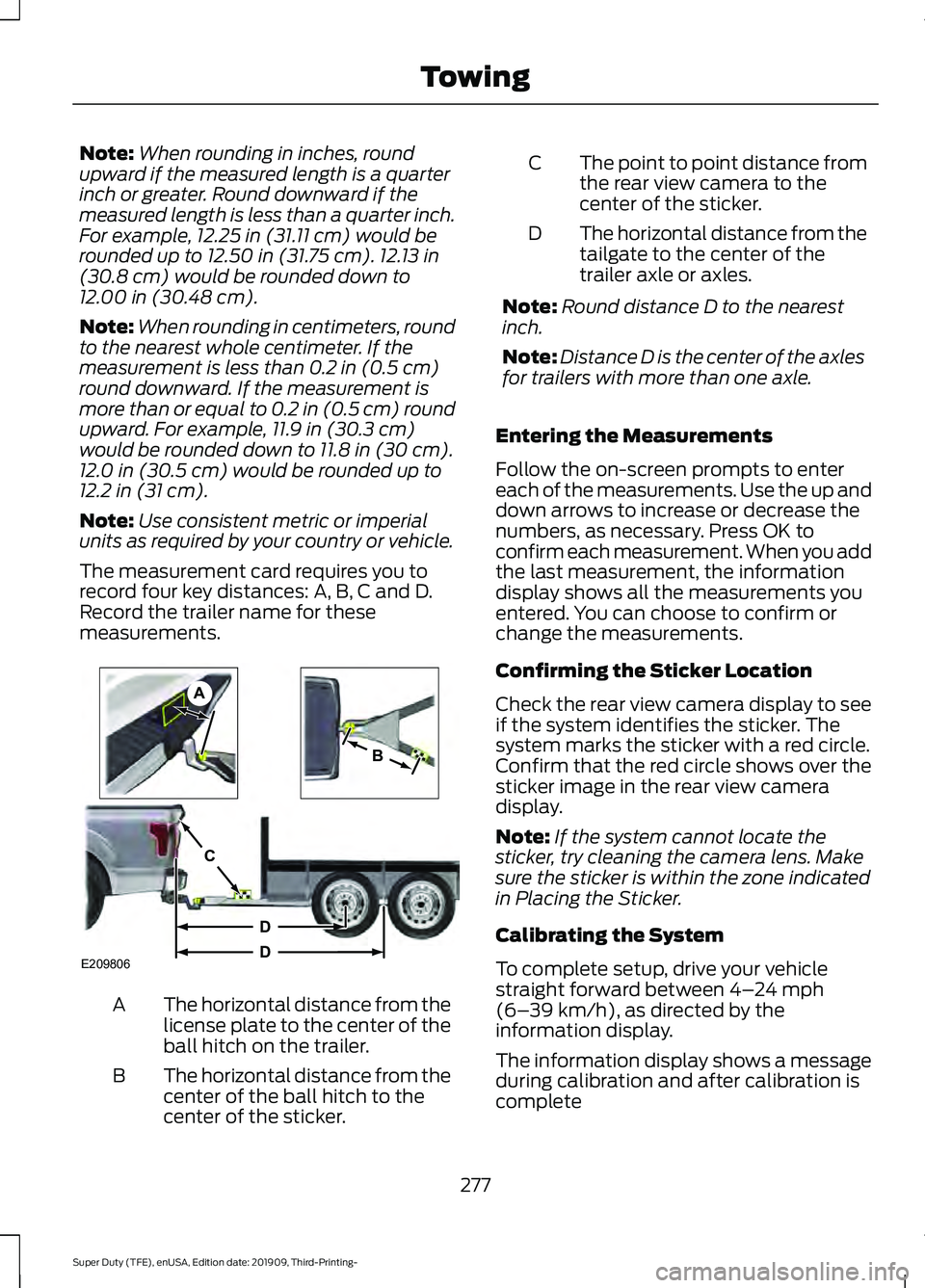
The measurement card requires you to
record four key distances: A, B, C and D.
Record the trailer name for these
measurements. The horizontal distance from the
license plate to the center of the
ball hitch on the trailer.
A
The horizontal distance from the
center of the ball hitch to the
center of the sticker.
B The point to point distance from
the rear view camera to the
center of the sticker.
C
The horizontal distance from the
tailgate to the center of the
trailer axle or axles.
D
Note: Round distance D to the nearest
inch.
Note: Distance D is the center of the axles
for trailers with more than one axle.
Entering the Measurements
Follow the on-screen prompts to enter
each of the measurements. Use the up and
down arrows to increase or decrease the
numbers, as necessary. Press OK to
confirm each measurement. When you add
the last measurement, the information
display shows all the measurements you
entered. You can choose to confirm or
change the measurements.
Confirming the Sticker Location
Check the rear view camera display to see
if the system identifies the sticker. The
system marks the sticker with a red circle.
Confirm that the red circle shows over the
sticker image in the rear view camera
display.
Note: If the system cannot locate the
sticker, try cleaning the camera lens. Make
sure the sticker is within the zone indicated
in Placing the Sticker.
Calibrating the System
To complete setup, drive your vehicle
straight forward between
4– 24 mph
(6– 39 km/h), as directed by the
information display.
The information display shows a message
during calibration and after calibration is
complete
277
Super Duty (TFE), enUSA, Edition date: 201909, Third-Printing- TowingE209806
A
B
C
D
D
Page 286 of 631
Measurement B has reached maximum or
minimum value:
•
Make sure that the sticker placement
instruction in step 3 of the setup has
been followed. Stickers placed outside
the allowed zone adversely affects the
system performance and could cause
improper feature function.
• Make sure that the measurement being
made is the horizontal distance only
from center of sticker to the hitch ball
center. A straight line distance that
includes any vertical rise or drop
increases the measurement and
causes an inaccurate value to be
entered into the system. See step 4 of
the setup for additional measurement
instructions.
Measurement C has reached maximum or
minimum value:
• Make sure you follow the sticker
placement instructions in step 3 of the
setup. Stickers placed outside the
allowed zone adversely affect the
system performance and could cause
improper feature function. If you have
met all the criteria for sticker
placement and you see this message,
the sticker is either too far below or too
close to the camera to properly
recognize the sticker. For the system
to operate correctly, the sticker height
must be lowered if you receive the
minimum warning or the sticker height
must be raised if you receive the
maximum warning.
• Only one sticker can be placed on the
trailer for correct system function. The
previous sticker must be removed or
covered so only one sticker is visible to
the camera.
• Measurement B and C must be
measured again if a new sticker is
placed on the trailer. Measurement D has reached maximum or
minimum value:
•
Make sure that the measurement being
made is the horizontal distance only
from tailgate to the center of the single
axle or the center of all the axles on the
trailer. See step 4 of the setup for
additional measurement instructions.
The system does not support trailer
lengths outside the range allowed by
the information display.
System is circling something beside the
sticker or system cannot find the sticker:
• Make sure the rear camera is clean and
the sticker is clearly visible in the
camera image. Clean the camera and
sticker if necessary.
• The camera system uses the entered
measurements to help locate the
sticker. Inaccurate sticker
measurements degrade the system ’s
ability to locate the sticker. Verify the
measurements you enter into the
system are accurate.
• Remove the incorrectly circled label or
decal if possible.
• If you cannot resolve the issue, try a
new sticker location. The sticker
location must still meet the
requirements noted in step 3 of the
setup instructions. Only one sticker can
be placed on the trailer for correct
system function. The previous sticker
must be removed or covered so only
one sticker is visible to the camera.
Calibration
The system monitors various vehicle
parameters to ensure your vehicle is being
driven straight and the trailer is straight
behind your vehicle. Any steering input or
trailer movement pauses the calibration.
283
Super Duty (TFE), enUSA, Edition date: 201909, Third-Printing- Towing