warning light FORD F-250 2020 Workshop Manual
[x] Cancel search | Manufacturer: FORD, Model Year: 2020, Model line: F-250, Model: FORD F-250 2020Pages: 631, PDF Size: 9.62 MB
Page 250 of 631
Note:
The overhead vehicle graphic may
still display if adaptive cruise control is
enabled.
While the system is on, the color of the
lane markings change to indicate the
system status.
Gray: Indicates that the system is
temporarily unable to provide a warning
on the indicated side(s). This may be
because:
• Your vehicle is under the activation
speed.
• The direction indicator is active.
• Your vehicle is in a dynamic maneuver.
• The road has no or poor lane markings
in the camera field-of-view.
• The camera is obscured or unable to
detect the lane markings due to
environmental, traffic or vehicle
conditions. For example, significant sun
angles, shadows, snow, heavy rain or
fog, following a large vehicle that is
blocking or shadowing the lane or poor
headlamp illumination. See
Troubleshooting for additional
information.
Green
: Indicates that the system is
available or ready to provide a warning on
the indicated side(s).
Red
: Indicates that the system is providing
or has just provided a lane keeping alert
warning.
You can temporarily disable the system at
any time by doing the following:
• Quick braking.
• Fast acceleration.
• Using your direction indicator.
• Evasive steering maneuver.
• Driving too close to the lane markings.
Troubleshooting Why is the feature not available (line markings are gray) when I can see the lane markings
on the road?
Your vehicle speed is outside the operational range of the feature.
The sun is shining directly into the camera lens.
A quick intentional lane change has occurred.
Your vehicle stays too close to the lane markings.
Driving at high speeds in curves.
The last feature activation occurred a short time ago.
Ambiguous lane markings, for example in construction zones.
Rapid transition from light to dark, or from dark to light.
Sudden offset in lane markings.
247
Super Duty (TFE), enUSA, Edition date: 201909, Third-Printing- Driving Aids
Page 252 of 631
Note:
The Blind Spot Information System
does not prevent contact with other vehicles
or objects; nor detect parked vehicles,
people, animals or infrastructure (fences,
guardrails, trees). It is only designed to alert
you to moving vehicles in the blind spot
zones.
Note: When a vehicle passes quickly
through the blind spot zone, typically fewer
than two seconds, the system does not
trigger.
Using the System
The Blind Spot Information System turns
on when you start the engine and you drive
your vehicle forward above 5 mph
(8 km/h).
For automatic transmissions, the Blind
Spot Information System remains on while
the transmission is in drive (D). If shifted
into reverse (R) or park (P) the Blind Spot
Information System turns off. Once shifted
back into drive (D), the Blind Spot
Information System turns back on when
you drive your vehicle above
5 mph
(8 km/h).
Note: For automatic transmissions, the
Blind Spot Information System does not
function in reverse (R) or park (P).
For manual transmissions, the Blind Spot
Information System is on for all gears
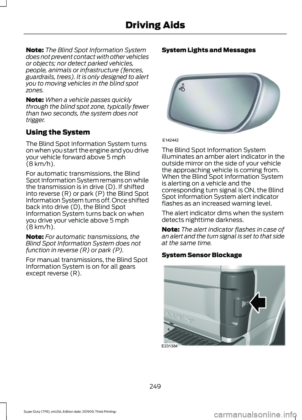
except reverse (R). System Lights and Messages The Blind Spot Information System
illuminates an amber alert indicator in the
outside mirror on the side of your vehicle
the approaching vehicle is coming from.
When the Blind Spot Information System
is alerting on a vehicle and the
corresponding turn signal is ON, the Blind
Spot Information System alert indicator
flashes as an increased warning level.
The alert indicator dims when the system
detects nighttime darkness.
Note:
The alert indicator flashes in case of
an alert and the turn signal is set to that side
at the same time.
System Sensor Blockage 249
Super Duty (TFE), enUSA, Edition date: 201909, Third-Printing- Driving AidsE142442 E231384
Page 254 of 631
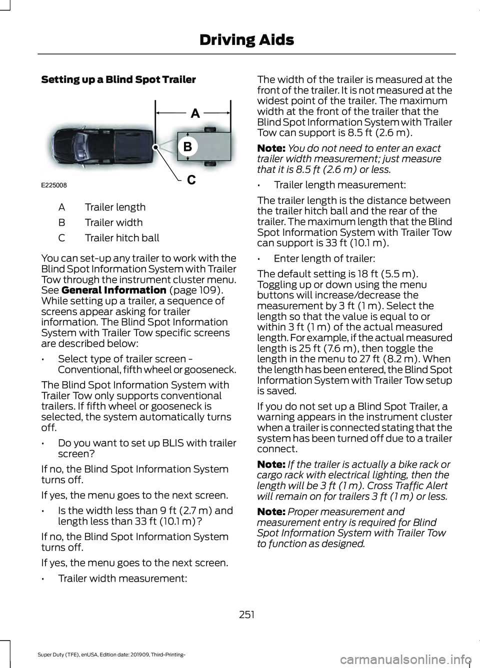
Setting up a Blind Spot Trailer
Trailer length
A
Trailer width
B
Trailer hitch ball
C
You can set-up any trailer to work with the
Blind Spot Information System with Trailer
Tow through the instrument cluster menu.
See General Information (page 109).
While setting up a trailer, a sequence of
screens appear asking for trailer
information. The Blind Spot Information
System with Trailer Tow specific screens
are described below:
• Select type of trailer screen -
Conventional, fifth wheel or gooseneck.
The Blind Spot Information System with
Trailer Tow only supports conventional
trailers. If fifth wheel or gooseneck is
selected, the system automatically turns
off.
• Do you want to set up BLIS with trailer
screen?
If no, the Blind Spot Information System
turns off.
If yes, the menu goes to the next screen.
• Is the width less than
9 ft (2.7 m) and
length less than 33 ft (10.1 m)?
If no, the Blind Spot Information System
turns off.
If yes, the menu goes to the next screen.
• Trailer width measurement: The width of the trailer is measured at the
front of the trailer. It is not measured at the
widest point of the trailer. The maximum
width at the front of the trailer that the
Blind Spot Information System with Trailer
Tow can support is
8.5 ft (2.6 m).
Note: You do not need to enter an exact
trailer width measurement; just measure
that it is
8.5 ft (2.6 m) or less.
• Trailer length measurement:
The trailer length is the distance between
the trailer hitch ball and the rear of the
trailer. The maximum length that the Blind
Spot Information System with Trailer Tow
can support is
33 ft (10.1 m).
• Enter length of trailer:
The default setting is
18 ft (5.5 m).
Toggling up or down using the menu
buttons will increase/decrease the
measurement by
3 ft (1 m). Select the
length so that the value is equal to or
within
3 ft (1 m) of the actual measured
length. For example, if the actual measured
length is
25 ft (7.6 m), then toggle the
length in the menu to 27 ft (8.2 m). When
the length has been entered, the Blind Spot
Information System with Trailer Tow setup
is saved.
If you do not set up a Blind Spot Trailer, a
warning appears in the instrument cluster
when a trailer is connected stating that the
system has been turned off due to a trailer
connect.
Note: If the trailer is actually a bike rack or
cargo rack with electrical lighting, then the
length will be
3 ft (1 m). Cross Traffic Alert
will remain on for trailers 3 ft (1 m) or less.
Note: Proper measurement and
measurement entry is required for Blind
Spot Information System with Trailer Tow
to function as designed.
251
Super Duty (TFE), enUSA, Edition date: 201909, Third-Printing- Driving AidsE225008
Page 261 of 631
Note:
During parking maneuvers, the
adaptive steering system balances the driver
work load for various steering wheel inputs
and vehicle loading conditions. Under
extreme operating conditions the system
locking device may engage. This strategy
prevents overheating and permanent
damage to the adaptive steering system.
Typical steering and driving maneuvers
allow the system to cool and return to
normal operation.
PRE-COLLISION ASSIST (IF
EQUIPPED) WARNING: You are responsible for
controlling your vehicle at all times. The
system is designed to be an aid and does
not relieve you of your responsibility to
drive with due care and attention. Failure
to follow this instruction could result in
the loss of control of your vehicle,
personal injury or death. WARNING:
The system does not
detect vehicles that are driving in a
different direction, cyclists or animals.
Apply the brakes when necessary. Failure
to follow this instruction could result in
the loss of control of your vehicle,
personal injury or death. WARNING:
The system does not
operate during hard acceleration or
steering. Failure to take care may lead
to a crash or personal injury. WARNING: The system may fail or
operate with reduced function during
cold and severe weather conditions.
Snow, ice, rain, spray and fog can
adversely affect the system. Keep the
front camera and radar free of snow and
ice. Failure to take care may result in the
loss of control of your vehicle, serious
personal injury or death. WARNING:
Some situations and
objects prevent hazard detection. For
example low or direct sunlight, inclement
weather, unconventional vehicle types,
and pedestrians. Apply the brakes when
necessary. Failure to follow this
instruction could result in the loss of
control of your vehicle, personal injury or
death. WARNING:
Take additional care if
your vehicle is heavily loaded or you are
towing a trailer. These conditions could
result in reduced performance of this
system. Failure to follow this instruction
could result in the loss of control of your
vehicle, personal injury or death. WARNING:
The system cannot
help prevent all crashes. Do not rely on
this system to replace driver judgment
and the need to maintain a safe distance
and speed.
Using the Pre-Collision Assist
System
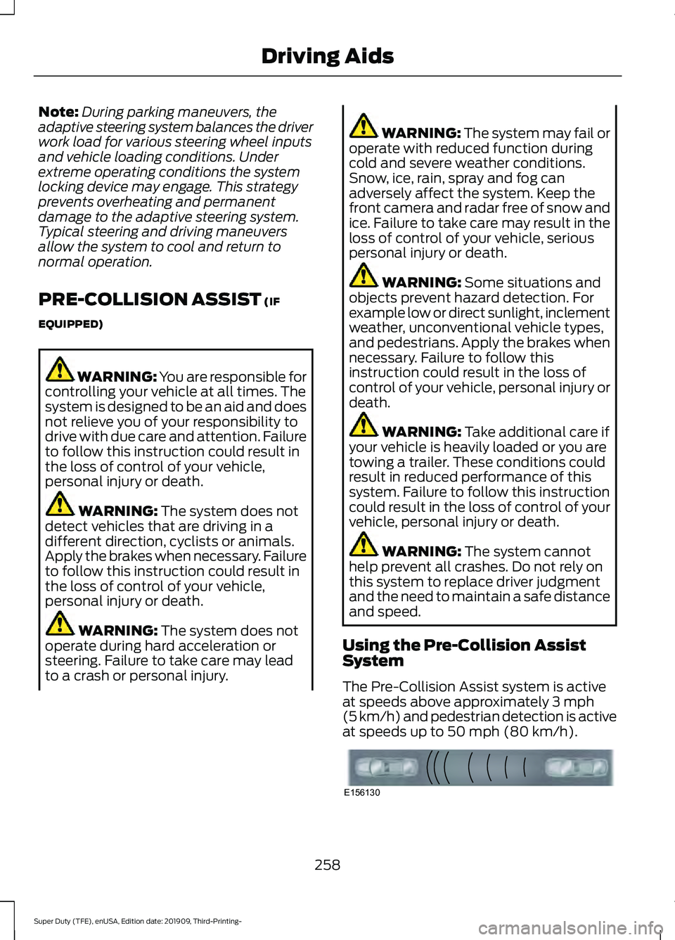
The Pre-Collision Assist system is active
at speeds above approximately
3 mph
(5 km/h) and pedestrian detection is active
at speeds up to
50 mph (80 km/h). 258
Super Duty (TFE), enUSA, Edition date: 201909, Third-Printing- Driving AidsE156130
Page 262 of 631
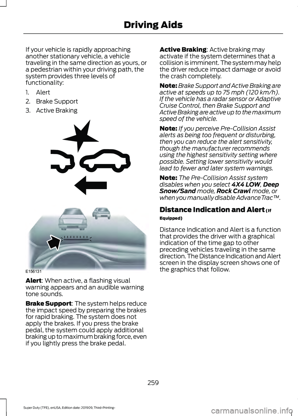
If your vehicle is rapidly approaching
another stationary vehicle, a vehicle
traveling in the same direction as yours, or
a pedestrian within your driving path, the
system provides three levels of
functionality:
1. Alert
2. Brake Support
3. Active Braking
Alert: When active, a flashing visual
warning appears and an audible warning
tone sounds.
Brake Support
: The system helps reduce
the impact speed by preparing the brakes
for rapid braking. The system does not
apply the brakes. If you press the brake
pedal, the system could apply additional
braking up to maximum braking force, even
if you lightly press the brake pedal. Active Braking
: Active braking may
activate if the system determines that a
collision is imminent. The system may help
the driver reduce impact damage or avoid
the crash completely.
Note: Brake Support and Active Braking are
active at speeds up to
75 mph (120 km/h).
If the vehicle has a radar sensor or Adaptive
Cruise Control, then Brake Support and
Active Braking are active up to the maximum
speed of the vehicle.
Note: If you perceive Pre-Collision Assist
alerts as being too frequent or disturbing,
then you can reduce the alert sensitivity,
though the manufacturer recommends
using the highest sensitivity setting where
possible. Setting lower sensitivity would
lead to fewer and later system warnings.
Note: The Pre-Collision Assist system
disables when you select
4X4 LOW, Deep
Snow/Sand mode, Rock Crawl mode, or
when you manually disable AdvanceTrac ™.
Distance Indication and Alert
(If
Equipped)
Distance Indication and Alert is a function
that provides the driver with a graphical
indication of the time gap to other
preceding vehicles traveling in the same
direction. The Distance Indication and Alert
screen in the display screen shows one of
the graphics that follow.
259
Super Duty (TFE), enUSA, Edition date: 201909, Third-Printing- Driving AidsE255268 E156131
Page 282 of 631
Note:
If your vehicle has the fifth wheel
prep package, you have everything you need.
If your vehicle does not have the fifth wheel
prep package, see your authorized dealer to
purchase the sensor kit and the 7/12 pin
connector.
Calibrating the System
During calibration, the system determines
the trailer length. The system supports
trailer lengths of 10– 39 ft (3– 11.94 m)
distance from the hitch point to the center
of the axle or axles.
To calibrate the system, you need an area
where you can safely drive forward and
turn left or right. An open parking lot is an
ideal place to perform the calibration.
Drive straight at approximately
5 mph
(8 km/h) to align the trailer behind your
vehicle. The information display and center
screen provide you with instructions and
tells you when the system is ready for a
turn. Turn left or right whenever you are
ready and in a safe turning area.
Note: You need to turn approximately 90
degrees to calibrate the system.
Note: The information display shows if you
are going too slow or fast. Calibration
pauses if the speed is outside the required
range of
2 – 16 mph (4– 25 km/h).
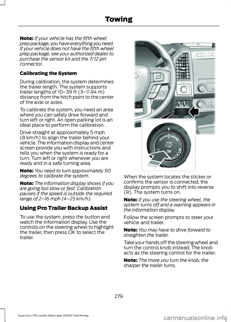
Using Pro Trailer Backup Assist
To use the system, press the button and
watch the information display. Use the
controls on the steering wheel to highlight
the trailer, then press OK to select the
trailer. When the system locates the sticker or
confirms the sensor is connected, the
display prompts you to shift into reverse
(R). The system turns on.
Note:
If you use the steering wheel, the
system turns off and a warning appears in
the information display.
Follow the screen prompts to steer your
vehicle and trailer.
Note: You may have to drive forward to
straighten the trailer.
Take your hands off the steering wheel and
turn the control knob instead. The knob
acts as the steering control for the trailer.
Note: The more you turn the knob, the
sharper the trailer turns.
279
Super Duty (TFE), enUSA, Edition date: 201909, Third-Printing- TowingE318266
Page 287 of 631
For best results:
•
Use a long, straight, smooth and level
road when attempting to calibrate.
• Drive straight forward.
• Drive between 4–24 mph
(6– 39 km/h).
System Operation
The following warnings or difficulties may
occur during feature operation. Tips to
resolve them are listed below.
Pro Trailer Backup Assist™ System is Not
Available or Trailer Reverse Guidance
System is Not Available:
• The system relies on many
sub-systems in your vehicle to correctly
operate. If those sub-systems are not
correctly operating, the system may
not be available.
• Low battery voltage is a condition that
prevents the system from operating.
Please make sure the battery is
correctly charged if the system is not
available.
• You may need to drive your vehicle
straight forward above
25 mph
(40 km/h) before the system is
available again.
• If the message continues to display,
see your authorized dealer for service.
Pro Trailer Backup Assist™ Driving
Required to Initialize Steering Press Knob
to Exit or Trailer Reverse Guidance Driving
Required to Initialize Steering Press OK to
Exit:
• The steering system needs to learn
internal parameters to fully enable the
feature. Drive your vehicle straight
forward above
25 mph (40 km/h) for
approximately 5 minutes.
• This may occur when your vehicle is
new, the battery voltage is too low, the
battery has been disconnected or your
steering system has been serviced. Sticker lost:
•
If the system cannot initially find the
sticker, it may be necessary for you to
change the lighting conditions by
moving the vehicle and trailer or
waiting until conditions change.
• Check for the following if you receive
the lost sticker message while using
the system.
• Stop your vehicle as soon as the
message displays.
• Make sure the sticker is visible and the
pattern is discernable in the rear view
camera image.
• Clean the sticker and camera to make
sure they are unobstructed.
• Clean the lens with a soft, lint-free
cloth and water.
• Clean the sticker with isopropyl rubbing
alcohol sprayed directly onto the
sticker, and then wipe clean with a soft
cloth.
• Remove any items that may be
blocking the view of the sticker.
Depending on your trailer configuration
and any equipment mounted to your
trailer, it is possible for the sticker to be
blocked from view of the camera as it
rotates on the hitch ball but not be
blocked during setup. Remove the
obstruction if possible. It may be
necessary to remove the sticker from
its current location if the obstruction
cannot be cleared. Place a new sticker
that is visible to the camera in all
positions of the trailer behind your
vehicle.
284
Super Duty (TFE), enUSA, Edition date: 201909, Third-Printing- Towing
Page 293 of 631
•
The trailer is not detected. Once your
vehicle is stopped, additional warnings
indicate the trailer is not detected.
Refer to trailer not detected
troubleshooting tips.
• An internal condition for system
operation was not met which requires
your vehicle to return to manual control
of the steering. Using the system for an
extended period of time can cause the
steering system to heat up and turn off
Pro Trailer Backup Assist steering
control to protect itself. The system
may require a cool down time of up to
30 minutes. Keep the system off and
drive forward at a normal speed or
switch the vehicle off.
TRAILER SWAY CONTROL (IF
EQUIPPED) WARNING: Turning off trailer sway
control increases the risk of loss of
vehicle control, serious injury or death.
Ford does not recommend disabling this
feature except in situations where speed
reduction may be detrimental (such as
hill climbing), the driver has significant
trailer towing experience, and can control
trailer sway and maintain safe operation.
Note: This feature does not prevent trailer
sway, but reduces it once it begins.
Note: This feature cannot stop all trailers
from swaying.
Note: In some cases, if vehicle speed is too
high, the system may activate multiple
times, gradually reducing vehicle speed. This feature applies your vehicle brakes at
individual wheels and, if necessary, reduces
engine power. If the trailer begins to sway,
the stability control light flashes and the
message
TRAILER SWAY REDUCE
SPEED appears in the information display.
The first thing to do is slow your vehicle
down, then pull safely to the side of the
road and check for proper tongue load and
trailer load distribution. See
Load
Carrying (page 265).
RECOMMENDED TOWING
WEIGHTS WARNING:
You must use
the heavy-duty drawbar pin
supplied with your vehicle when
using the heavy-duty hitch.
Failure to follow this instruction
could result in the loss of control
of your vehicle, personal injury or
death.
Note: Vehicles with a
21,200 lb
(9,616 kg) hitch and above must
use the drawbar pin that came with
the vehicle. You can obtain a
replacement drawbar pin at your
authorized dealer.
Note: Make sure to take into
consideration trailer frontal area.
Do not exceed 60 ft² (5.6 m²)
trailer frontal area for conventional
trailers. Do not exceed 75 ft² (6.9
m²) trailer frontal area for fifth
wheel and gooseneck trailers.
290
Super Duty (TFE), enUSA, Edition date: 201909, Third-Printing- Towing
Page 298 of 631
ESSENTIAL TOWING CHECKS
WARNING: Do not exceed the
maximum vertical load on the tow ball.
Failure to follow this instruction could
result in the loss of control of your
vehicle, personal injury or death.
Follow these guidelines for safe towing:
• Do not tow a trailer until you drive your
vehicle at least
1,000 mi (1,600 km).
• Consult your local motor vehicle laws
for towing a trailer.
• See the instructions included with
towing accessories for the proper
installation and adjustment
specifications.
• Service your vehicle more frequently if
you tow a trailer. See your scheduled
maintenance information.
See
Scheduled Maintenance (page 553).
• If you use a rental trailer, follow the
instructions the rental agency gives
you.
See
Load Limits in the Load Carrying
chapter for load specification terms found
on the tire label and Safety Compliance
label and instructions on calculating your
vehicle's load.
Vehicles with a diesel engine have an
engine braking feature.
See General
Information (page 217).
Remember to account for the trailer
tongue weight as part of your vehicle load
when calculating the total vehicle weight.
Some vehicles will have the ability to
modify trailer towing features. See
General Information
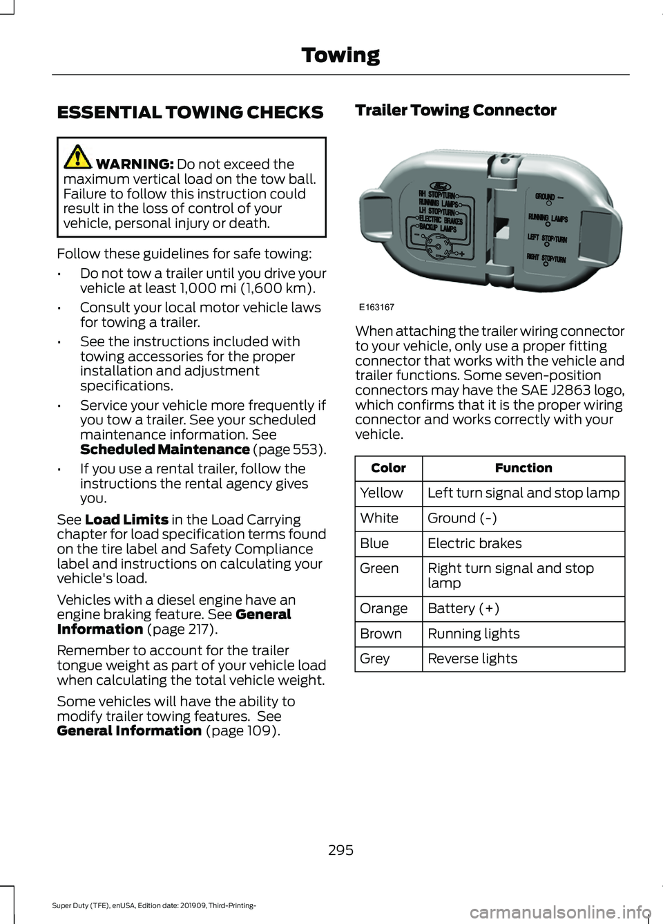
(page 109). Trailer Towing Connector
When attaching the trailer wiring connector
to your vehicle, only use a proper fitting
connector that works with the vehicle and
trailer functions. Some seven-position
connectors may have the SAE J2863 logo,
which confirms that it is the proper wiring
connector and works correctly with your
vehicle.
Function
Color
Left turn signal and stop lamp
Yellow
Ground (-)
White
Electric brakes
Blue
Right turn signal and stop
lamp
Green
Battery (+)
Orange
Running lights
Brown
Reverse lights
Grey
295
Super Duty (TFE), enUSA, Edition date: 201909, Third-Printing- TowingE163167
Page 301 of 631
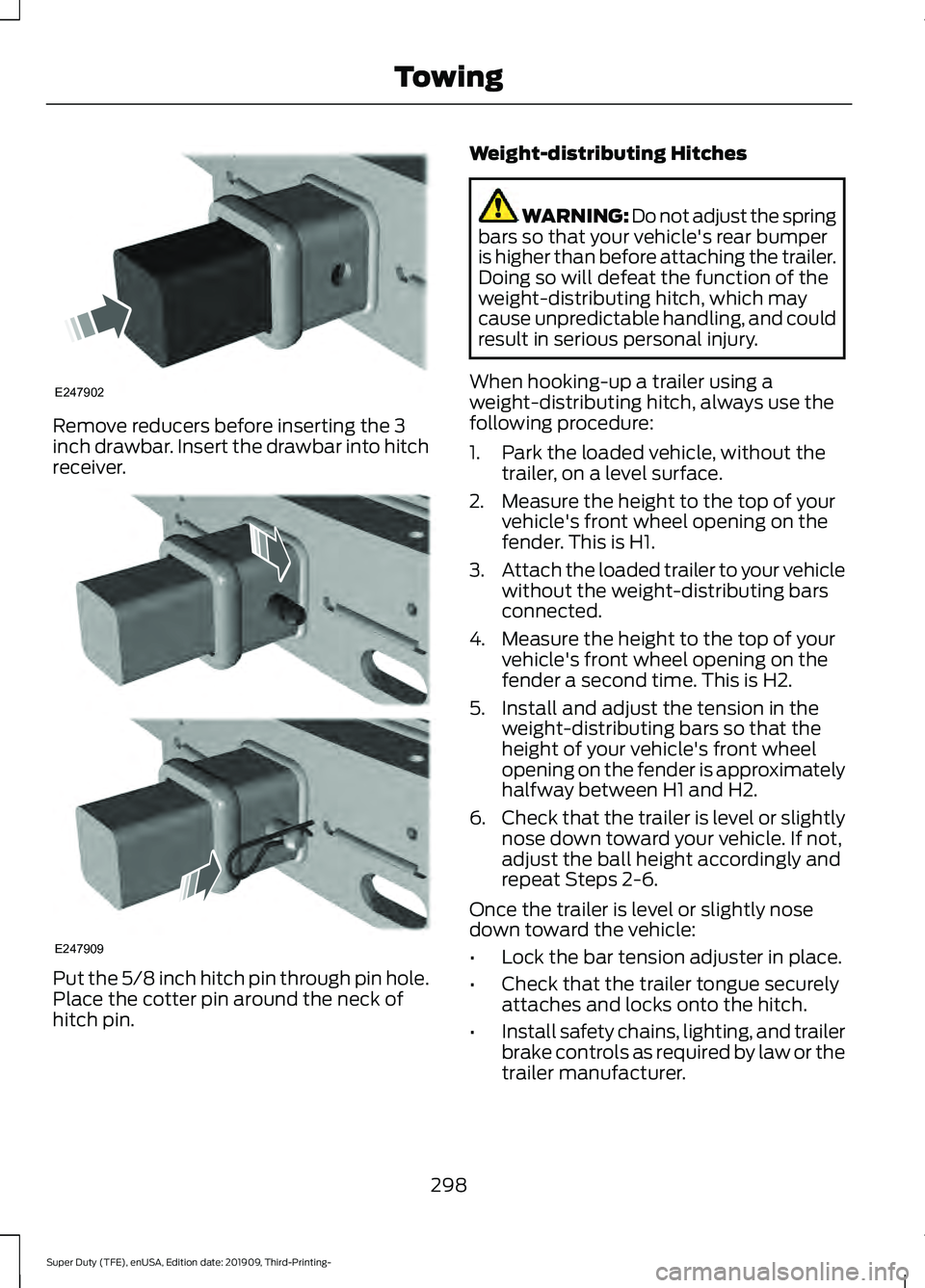
Remove reducers before inserting the 3
inch drawbar. Insert the drawbar into hitch
receiver.
Put the 5/8 inch hitch pin through pin hole.
Place the cotter pin around the neck of
hitch pin. Weight-distributing Hitches WARNING: Do not adjust the spring
bars so that your vehicle's rear bumper
is higher than before attaching the trailer.
Doing so will defeat the function of the
weight-distributing hitch, which may
cause unpredictable handling, and could
result in serious personal injury.
When hooking-up a trailer using a
weight-distributing hitch, always use the
following procedure:
1. Park the loaded vehicle, without the trailer, on a level surface.
2. Measure the height to the top of your vehicle's front wheel opening on the
fender. This is H1.
3. Attach the loaded trailer to your vehicle
without the weight-distributing bars
connected.
4. Measure the height to the top of your vehicle's front wheel opening on the
fender a second time. This is H2.
5. Install and adjust the tension in the weight-distributing bars so that the
height of your vehicle's front wheel
opening on the fender is approximately
halfway between H1 and H2.
6. Check that the trailer is level or slightly
nose down toward your vehicle. If not,
adjust the ball height accordingly and
repeat Steps 2-6.
Once the trailer is level or slightly nose
down toward the vehicle:
• Lock the bar tension adjuster in place.
• Check that the trailer tongue securely
attaches and locks onto the hitch.
• Install safety chains, lighting, and trailer
brake controls as required by law or the
trailer manufacturer.
298
Super Duty (TFE), enUSA, Edition date: 201909, Third-Printing- TowingE247902 E247909