service indicator FORD F-350 2021 User Guide
[x] Cancel search | Manufacturer: FORD, Model Year: 2021, Model line: F-350, Model: FORD F-350 2021Pages: 666, PDF Size: 11.3 MB
Page 230 of 666
PRINCIPLE OF OPERATION
The traction control system helps avoid
drive wheel spin and loss of traction.
If your vehicle begins to slide, the system
applies the brakes to individual wheels
and, when needed, reduces engine power
at the same time. If the wheels spin when
accelerating on slippery or loose surfaces,
the system reduces engine power in order
to increase traction.
USING TRACTION CONTROL
WARNING: The stability and
traction control light illuminates steadily
if the system detects a failure. Make sure
you did not manually disable the traction
control system using the information
display controls or the switch. If the
stability control and traction control light
is still illuminating steadily, have the
system serviced by an authorized dealer
immediately. Operating your vehicle with
the traction control disabled could lead
to an increased risk of loss of vehicle
control, vehicle rollover, personal injury
and death.
The system automatically turns on each
time you switch the ignition on.
If your vehicle is stuck in mud or snow,
switching traction control off may be
beneficial as this allows the wheels to spin.
Note: When you switch traction control off,
stability control remains fully active.
Note: For additional information on the
traction and stability control systems. See
Using Stability Control
(page 229). Switching the System Off
When you switch the system off or on, a
message appears in the information
display showing system status.
Use the traction and stability control
switch on the instrument panel to switch
the system off or on.
The switch illuminates when traction
control is off.
When you place your vehicle into
four-wheel drive low mode the traction
control disables. Traction control resumes
full operation when you put your vehicle
back into two-wheel drive mode.
System Indicator Lights and
Messages
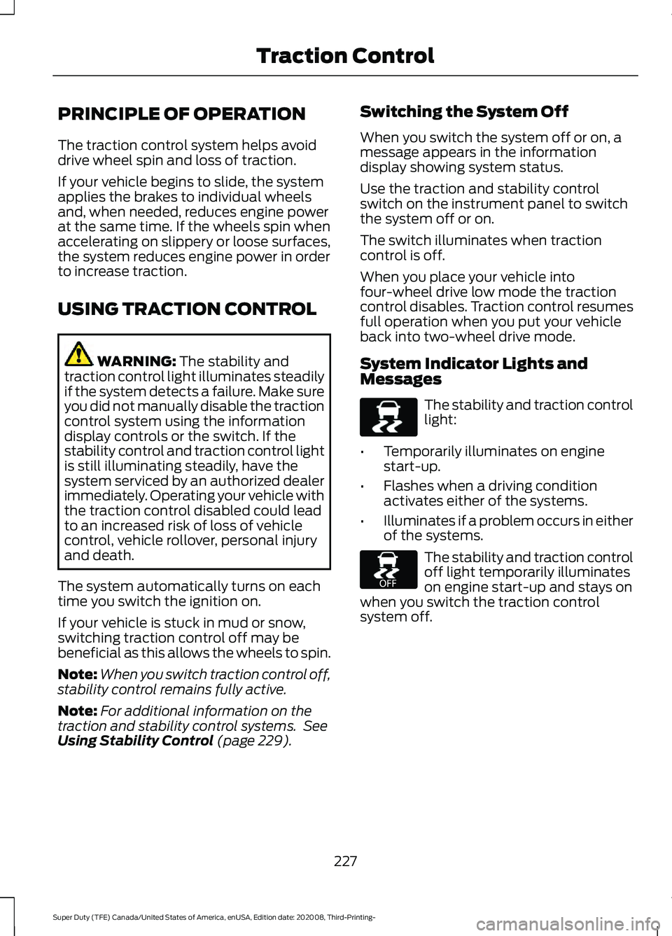
The stability and traction control
light:
• Temporarily illuminates on engine
start-up.
• Flashes when a driving condition
activates either of the systems.
• Illuminates if a problem occurs in either
of the systems. The stability and traction control
off light temporarily illuminates
on engine start-up and stays on
when you switch the traction control
system off.
227
Super Duty (TFE) Canada/United States of America, enUSA, Edition date: 202008, Third-Printing- Traction ControlE225465 E225466
Page 319 of 666
Note:
You can check four-wheel-down
towing status at any time by opening the
driver's door or turning the ignition to the
accessory or on position. A message
displays in the information display
confirming your vehicle is in neutral tow.
When finished towing with all four wheels
on the ground return the transfer case to
its 2H position:
1. With your vehicle still properly secured
to the tow vehicle, put the ignition in
the on position, but do not start the
engine. If your vehicle has an ignition
key, switch the key to on. If your vehicle
has intelligent access, switch the
vehicle into accessory mode. See
Starting and Stopping the Engine
(page
174).
2. Press and hold the brake pedal.
3. Shift out of neutral (N).
4. Release the brake pedal.
Note: If completed successfully, the
instrument cluster displays 2H and Neutral
Tow Disabled
.
Note: If the indicator light and message do
not display, you must perform the procedure
again from the beginning.
Note: If
Shift Delayed Pull Forward
displays in the instrument cluster, a transfer
case blockage is present. See resolving the
shift delayed pull forward message
instructions after this section.
5. Apply the parking brake and disconnect
the vehicle from the tow vehicle.
6. Release the parking brake, start the engine and shift the transmission to
drive (D) to make sure the transfer
case is out of neutral (N).
7. If the transfer case does not successfully shift out of neutral (N),
set the parking brake until you can have
your vehicle serviced. Resolving the
Shift Delayed Pull Forward
Message
1. Press and hold the brake pedal.
2. Put the transmission into neutral (N),
and then start the engine.
3. With the engine running, shift the transmission to drive (D) and let the
vehicle roll forward, up to
3 ft (1 m).
4. Make sure the instrument cluster displays that neutral tow is disabled.
316
Super Duty (TFE) Canada/United States of America, enUSA, Edition date: 202008, Third-Printing- Towing
Page 329 of 666
Vehicles Sold in Canada: Getting
Roadside Assistance
To fully assist you should you have a
vehicle concern, Ford Motor Company of
Canada, Limited offers a complimentary
roadside assistance program. This program
is eligible within Canada or the continental
United States.
The service is available 24 hours a day,
seven days a week.
This program is separate from the New
Vehicle Limited Warranty, but the coverage
is concurrent with the powertrain coverage
period of your vehicle. Canadian roadside
coverage and benefits may differ from the
U.S. coverage.
If you require more information, please call
us in Canada at 1-800-665-2006, or visit
our website at www.ford.ca.
HAZARD FLASHERS
Note:
The hazard flashers operate when
the ignition is in any position, or if the key is
not in the ignition. If used when the vehicle
is not running, the battery loses charge. As
a result, there may be insufficient power to
restart your vehicle. The flasher control is on the
instrument panel. Use your
hazard flashers when your
vehicle is creating a safety hazard for other
motorists.
• Press the flasher control and all front
and rear direction indicators flash.
• Press the button again to switch them
off. FUEL SHUTOFF WARNING: If your vehicle has been
involved in a crash, have the fuel system
checked. Failure to follow this instruction
could result in fire, personal injury or
death.
Note: When you try to restart your vehicle
after a fuel shutoff, the vehicle makes sure
that various systems are safe to restart.
Once the vehicle determines the systems
are safe, then the vehicle allows you to
restart.
Note: In the event that your vehicle does
not restart after your third attempt, contact
a qualified technician.
The fuel pump shutoff stops the flow of
fuel to the engine in the event of a
moderate to severe crash. Not every
impact causes a shutoff.
Should your vehicle shut off after a crash,
you may restart your vehicle.
If your vehicle has a key system:
1. Switch off the ignition.
2. Switch to start position.
3. Switch off the ignition.
4. Switch on the ignition to re-enable the
fuel pump.
5. If the vehicle does not start, repeat steps 1 through 4.
If your vehicle has a push button start
system:
1. Press START/STOP to switch off your
vehicle.
2. Press the brake pedal and START/STOP
to switch on your
vehicle.
3. Remove your foot from the brake pedal
and press
START/STOP to switch off
your vehicle.
326
Super Duty (TFE) Canada/United States of America, enUSA, Edition date: 202008, Third-Printing- Roadside Emergencies
Page 332 of 666
2. Remove the jumper cable on the
negative (-) terminal of the booster
vehicle battery.
3. Remove the jumper cable from the positive (+) terminal of the booster
vehicle battery.
4. Remove the jumper cable from the positive (+) terminal of the disabled
vehicle battery.
5. Allow the engine to idle for at least one
minute.
POST-CRASH ALERT SYSTEM
The system flashes the direction indicators
and sounds the horn (intermittently) in the
event of a serious impact that deploys an
airbag (front, side, side curtain or Safety
Canopy) or the seatbelt pretensioners.
The horn and indicators turn off when:
• You press the hazard control button.
• You press the panic button on the
remote entry transmitter (if equipped).
• Your vehicle runs out of power.
• Sounding of the horn is only enabled
in specific markets.
TRANSPORTING THE VEHICLE WARNING: Block the wheels to
help prevent the vehicle from moving. WARNING:
Unexpected and
possibly sudden vehicle movement may
occur if you do not take these
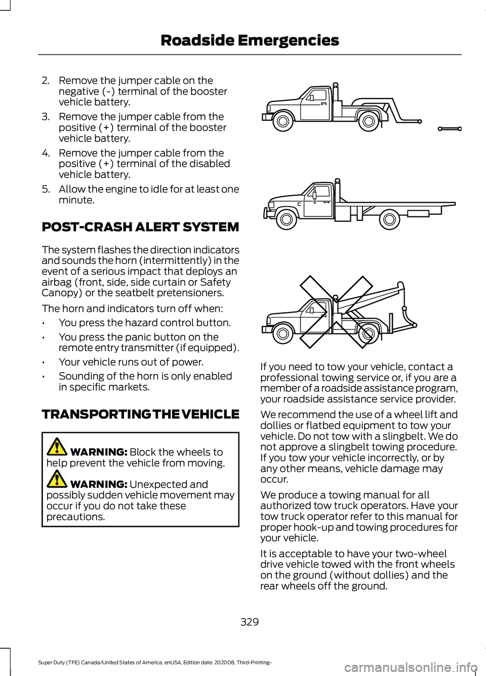
precautions. If you need to tow your vehicle, contact a
professional towing service or, if you are a
member of a roadside assistance program,
your roadside assistance service provider.
We recommend the use of a wheel lift and
dollies or flatbed equipment to tow your
vehicle. Do not tow with a slingbelt. We do
not approve a slingbelt towing procedure.
If you tow your vehicle incorrectly, or by
any other means, vehicle damage may
occur.
We produce a towing manual for all
authorized tow truck operators. Have your
tow truck operator refer to this manual for
proper hook-up and towing procedures for
your vehicle.
It is acceptable to have your two-wheel
drive vehicle towed with the front wheels
on the ground (without dollies) and the
rear wheels off the ground.
329
Super Duty (TFE) Canada/United States of America, enUSA, Edition date: 202008, Third-Printing- Roadside EmergenciesE143886
Page 359 of 666
3. Add engine oil that meets the correct
specification.
4. Recheck the oil level.
5. If the oil level is correct, replace the dipstick and make sure it is fully seated.
6. Replace the engine oil filler cap. Turn it clockwise until you feel a strong
resistance.
Note: Do not add oil further than the
maximum mark. Oil levels above the
maximum mark may cause engine damage.
Note: Make sure you install the oil filler cap
correctly.
Note: Soak up any spillage with an
absorbent cloth immediately.
CHANGING THE ENGINE OIL
AND OIL FILTER
If your vehicle is equipped with a diesel
engine, an Intelligent Oil Life Monitor™
calculates the proper oil change service
interval. When the information display
indicates: OIL CHANGE REQUIRED, change
the engine oil and oil filter. See
Information Displays (page 110).
The engine oil filter protects your engine
by filtering harmful, abrasive or sludge
particles and particles significantly smaller
than most available will-fit filters. See
Motorcraft Parts
(page 443).
1. Unscrew the oil filter and oil pan drain plug and wait for the oil to drain.
2. Replace the filter.
Note: Do not handle hot oil filter with bare
hands.
3. Reinstall the oil pan drain plug.
4. Refill the engine with new oil. See Engine Oil Capacity and
Specification
(page 449). 5. For diesel engines, you need to reset
the Intelligent Oil Life Monitor™. See
Information Displays
(page 110).
Engine lubrication for severe
service operation
The following conditions define severe
operation for which engine operation with
SAE 5W-40 that meets our specification
WSS-M2C171-F1 is recommended. Oil and
oil filter change intervals will be
determined by the Intelligent Oil Life
Monitor™ as noted previously.
• Frequent or extended idling (over 10
minutes per hour of normal driving).
• Low-speed operation/stationary use.
• If vehicle is operated in sustained
ambient temperatures below
-9°F
(-23°C) or above 100°F (38°C).
• Frequent low-speed operation,
consistent heavy traffic less than
25 mph (40 km/h)
.
• Operating in severe dust conditions.
• Operating the vehicle off road.
• Towing a trailer over
1,000 mi
(1,600 km).
• Sustained, high-speed driving at Gross
Vehicle Weight Rating (maximum
loaded weight for vehicle operation).
• Use of fuels with sulfur content other
than ultra-low sulfur diesel (ULSD).
• Use of high-sulfur diesel fuel.
OIL CHANGE INDICATOR
RESET
Use the information display controls on
the steering wheel to reset the oil change
indicator.
356
Super Duty (TFE) Canada/United States of America, enUSA, Edition date: 202008, Third-Printing- Maintenance
Page 360 of 666
From the main menu scroll to:
Action and description
Message
Press the down arrow
button, then from this menu
scroll to the following
message.
Truck Info
Press the OK button.
Mainten-
ance
Monitor
Press the down arrow
button, then from this menu
scroll to the following
message.
Oil Life:
xxx%
Press the
OK button.
Oil Life
Press and hold the
OK
button until the instrument
cluster displays the
following message.
Oil Life
Hold OK to
Reset
Oil Life: 100%
When the oil change indic-
ator resets the instrument
cluster displays 100%.
Repeat the process if the oil
change indicator does not
reset.
CHANGING THE ENGINE AIR
FILTER - 6.2L WARNING:
To reduce the risk of
vehicle damage and personal burn
injuries, do not start your engine with the
air cleaner removed and do not remove
it while the engine is running.
Use the correct specification air filter
element. See
Motorcraft Parts (page
443). Note:
Failure to use the correct air filter
element may result in severe engine
damage. Resulting component damage
may not be covered by the vehicle Warranty.
Change the air filter element at the correct
service interval. See
Scheduled
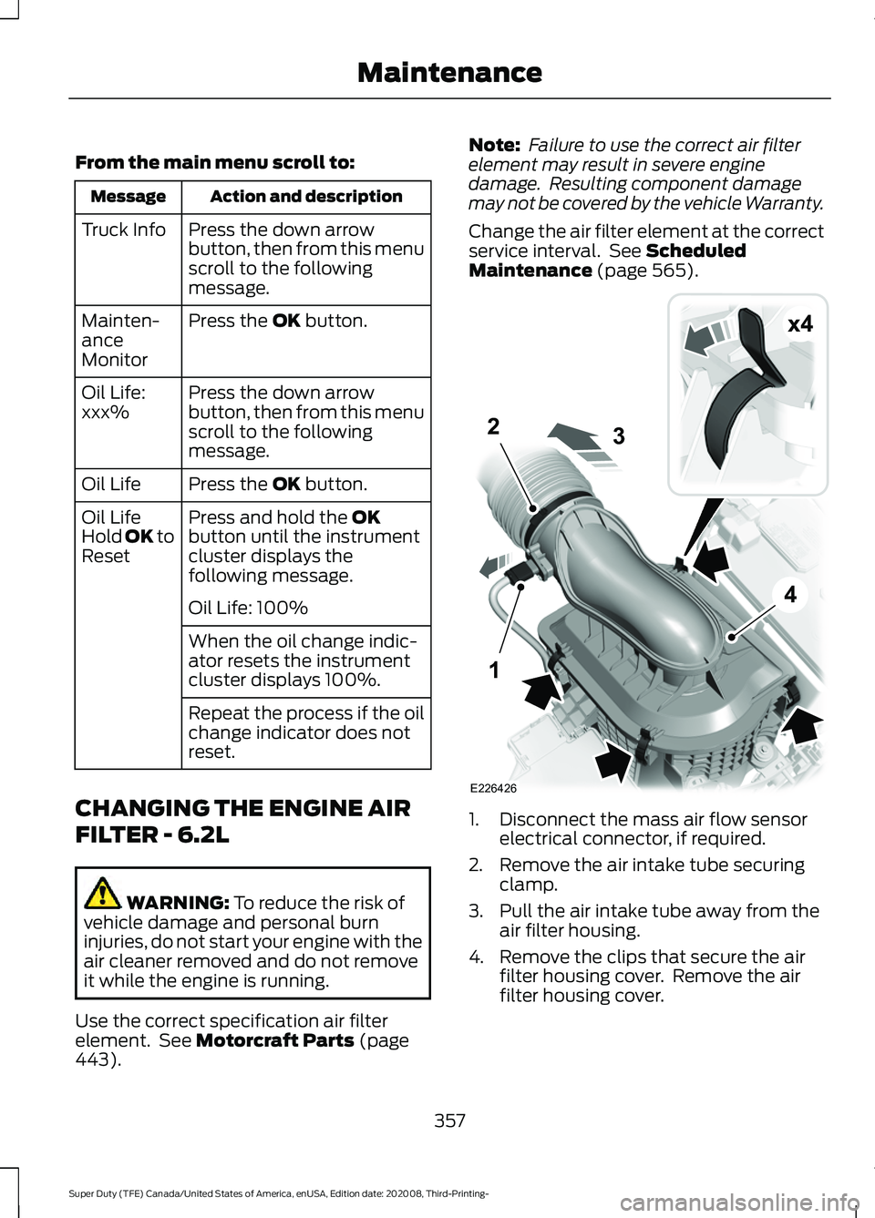
Maintenance (page 565). 1. Disconnect the mass air flow sensor
electrical connector, if required.
2. Remove the air intake tube securing clamp.
3. Pull the air intake tube away from the air filter housing.
4. Remove the clips that secure the air filter housing cover. Remove the air
filter housing cover.
357
Super Duty (TFE) Canada/United States of America, enUSA, Edition date: 202008, Third-Printing- MaintenanceE226426
x4
1
2
4
3
Page 420 of 666
WARNING: To reduce the
risk of serious injury, when
mounting replacement tires and
wheels, you should not exceed
the maximum pressure indicated
on the sidewall of the tire to set
the beads without additional
precautions listed below. If the
beads do not seat at the
maximum pressure indicated,
re-lubricate and try again.
When inflating the tire for
mounting pressures up to 20 psi
(1.38 bar)
greater than the
maximum pressure on the tire
sidewall, the following
precautions must be taken to
protect the person mounting the
tire:
1. Make sure that you have the
correct tire and wheel size.
2. Lubricate the tire bead and
wheel bead seat area again.
3. Stand at a minimum of
12 ft
(3.66 m) away from the wheel
and tire assembly.
4. Use both eye and ear
protection. WARNING: For a mounting
pressure more than
20 psi
(1.38 bar) greater than the
maximum pressure, a Ford
dealer or other tire service
professional should do the
mounting. WARNING:
Always inflate
steel carcass tires with a remote
air fill with the person inflating
standing at a minimum of
12 ft
(3.66 m) away from the wheel
and tire assembly.
Important: Remember to replace
the wheel valve stems when the
road tires are replaced on your
vehicle.
The two front tires or two rear tires
should generally be replaced as a
pair.
The tire pressure sensors mounted
in the wheels are not designed to
be used in aftermarket wheels.
The use of wheels or tires not
recommended by Ford Motor
Company may affect the
operation of your tire pressure
monitoring system.
If the tire pressure monitoring
system indicator is flashing, the
system is malfunctioning. Your
replacement tire might be
incompatible with your tire
pressure monitoring system, or
some component of the system
may be damaged.
417
Super Duty (TFE) Canada/United States of America, enUSA, Edition date: 202008, Third-Printing- Wheels and Tires
Page 429 of 666
•
To reduce the chances of interference
from another vehicle, perform the
system reset procedure at least 3 ft
(1 m) away from another Ford Motor
Company vehicle undergoing the
system reset procedure at the same
time.
• Do not wait more than two minutes
between resetting each tire sensor or
the system can time-out and you have
to repeat the entire procedure on all
four wheels.
• A double horn sounds indicating the
need to repeat the procedure.
Performing the System Reset Procedure
- Single Rear Wheel
Read the entire procedure before
attempting.
1. Drive the vehicle above
20 mph
(32 km/h) for at least two minutes,
then park in a safe location where you
can easily get to all four tires and have
access to an air pump.
2. Place the ignition in the off position and
keep the key in the ignition.
3. Cycle the ignition to the on position with the engine off.
4. Turn the hazard flashers on then off three times. You must accomplish this
within 10 seconds. If you successfully
enter the reset mode, the horn sounds
once, the system indicator flashes and
a message shows in the information
display. If this does not occur, please
try again starting at step 2. If after
repeated attempts to enter the reset
mode, the horn does not sound, the
system indicator does not flash and no
message shows in the information
display, seek service from your
authorized dealer. 5. Train the tire pressure monitoring
system sensors in the tires using the
following system reset sequence
starting with the left front tire in the
following clockwise order: Left front -
driver side front tire, Right front -
passenger side front tire, Right rear -
passenger side rear tire, Left rear -
driver side rear tire.
6. Remove the valve cap from the valve stem on the left front tire. Decrease the
air pressure until the horn sounds.
Note: The single horn tone confirms that
the sensor identification code has been
learned by the module for this position. If a
double horn is heard, the reset procedure
was unsuccessful, and you must repeat it.
7. Remove the valve cap from the valve stem on the right front tire. Decrease
the air pressure until the horn sounds.
8. Remove the valve cap from the valve stem on the right rear tire. Decrease the
air pressure until the horn sounds.
9. Remove the valve cap from the valve stem on the left rear tire. Decrease the
air pressure until the horn sounds.
Training is complete after the horn
sounds for the last tire trained, driver
side rear tire, the system indicator
stops flashing, and a message shows
in the information display.
10. Turn the ignition off. If two short horn
beeps are heard, the reset procedure
was unsuccessful and you must
repeat it. If after repeating the
procedure and two short beeps are
heard when the ignition is turned to
off, seek assistance from your
authorized dealer.
426
Super Duty (TFE) Canada/United States of America, enUSA, Edition date: 202008, Third-Printing- Wheels and Tires
Page 430 of 666
11.
Set all four tires to the recommended
air pressure as indicated on the
Safety Compliance Certification
Label, affixed to either the door hinge
pillar, door-latch post, or the door
edge that meets the door-latch post,
next to the driver seating position or
Tire Label located on the B-Pillar or
the edge of the driver door.
Performing the System Reset Procedure
- Dual Rear Wheel
For further information see
Understanding Your Tire Pressure
Monitoring System and refer to Dual
Rear Wheel, earlier in this section.
Read the entire procedure before
attempting.
1. Drive the vehicle above
20 mph
(32 km/h) for at least two minutes,
then park in a safe location where you
can easily get to all six tires and have
access to an air pump.
2. Place the ignition in the off position and
keep the key in the ignition.
3. Cycle the ignition to the on position with the engine off.
4. Turn the hazard flashers on then off three times. You must accomplish this
within 10 seconds. If you successfully
enter the reset mode, the horn sounds
once, the system indicator flashes and
a message shows in the information
display. If this does not occur, please
try again starting at step 2. If after
repeated attempts to enter the reset
mode, the horn does not sound, the
system indicator does not flash and no
message shows in the information
display, seek service from your
authorized dealer. 5. Train the tire pressure monitoring
system sensors in the tires using the
following system reset sequence
starting with the left front tire in the
following order: Left front - driver side
front tire, Right front - passenger side
front tire, Right outer rear -passenger
side rear outer tire, Right inner rear -
passenger side rear inner tire, Left outer
rear - driver side rear outer tire, Left
inner rear - driver side rear inner tire.
6. Remove the valve cap from the valve stem on the left front tire. Decrease the
air pressure until the horn sounds.
Note: The single horn chirp confirms that
the sensor identification code has been
learned by the module for this position. If a
double horn is heard, the reset procedure
was unsuccessful, and you must repeat it.
7. Remove the valve cap from the valve stem on the right front tire. Decrease
the air pressure until the horn sounds.
8. Remove the valve cap from the valve stem on the right outer rear tire.
Decrease the air pressure until the horn
sounds.
9. Remove the valve cap from the valve stem on the right inner rear tire.
Decrease the air pressure until the horn
sounds.
10. Remove the valve cap from the valve
stem on the left outer rear tire.
Decrease the air pressure until the
horn sounds.
11. Remove the valve cap from the valve
stem on the left inner rear tire.
Decrease the air pressure until the
horn sounds. Training is complete
after the horn sounds for the last tire
trained, the system indicator stops
flashing, and a message is shown in
the information display.
427
Super Duty (TFE) Canada/United States of America, enUSA, Edition date: 202008, Third-Printing- Wheels and Tires
Page 432 of 666
The trailer tire pressure monitoring system
can be reset through the menu in the
information display. See General
Information (page 110). Performing the
trailer setup process also resets the trailer
tire pressure monitoring system.
CHANGING A ROAD WHEEL WARNING:
If the tire pressure
monitor sensor becomes damaged it
may not function.
Note: If your vehicle is equipped with the
tire pressure monitoring system, the
indicator light illuminates when the spare
tire is in use. To restore the full function of
the monitoring system, all road wheels
equipped with tire pressure monitoring
sensors must be mounted on the vehicle.
Note: You should only use tire sealants in
roadside emergencies as they may cause
damage to the tire pressure monitoring
system sensor.
If you get a flat tire when driving, do not
apply the brake heavily. Instead, gradually
decrease your speed. Hold the steering
wheel firmly and slowly move to a safe
place on the side of the road.
If your vehicle is equipped with the tire
pressure monitoring system, have a flat
serviced by an authorized dealer in order
to prevent damage to the system sensors.
See
Tire Pressure Monitoring System
(page 421). Replace the spare tire with a
road tire as soon as possible. During
repairing or replacing of the flat tire, have
the authorized dealer inspect the system
sensor for damage. Dissimilar Spare Wheel and Tire
Assembly Information WARNING:
Failure to follow these
guidelines could result in an increased
risk of loss of vehicle control, injury or
death.
If you have a dissimilar spare wheel and
tire, then it is intended for temporary use
only. This means that if you need to use it,
you should replace it as soon as possible
with a road wheel and tire assembly that
is the same size and type as the road tires
and wheels that were originally provided
by Ford. If the dissimilar spare tire or wheel
is damaged, it should be replaced rather
than repaired.
A dissimilar spare wheel and tire assembly
is defined as a spare wheel and tire
assembly that is different in brand, size or
appearance from the road tires and
wheels.
Full-size dissimilar spare
When driving with the full-size dissimilar
spare wheel and tire assembly, do not:
• Exceed
70 mph (113 km/h).
• Use more than one dissimilar spare
wheel and tire assembly at a time.
• Use snow chains on the end of the
vehicle with the dissimilar spare wheel
and tire assembly.
When driving with the full-size dissimilar
spare wheel and tire assembly, 4WD
functionality may be limited. You may
experience the following:
• Additional noise from the transfer case
or other drive components.
• Difficulty shifting out of a mechanically
locked 4WD mode.
429
Super Duty (TFE) Canada/United States of America, enUSA, Edition date: 202008, Third-Printing- Wheels and Tires