FORD F-350 2022 Owners Manual
Manufacturer: FORD, Model Year: 2022, Model line: F-350, Model: FORD F-350 2022Pages: 740, PDF Size: 12.6 MB
Page 321 of 740
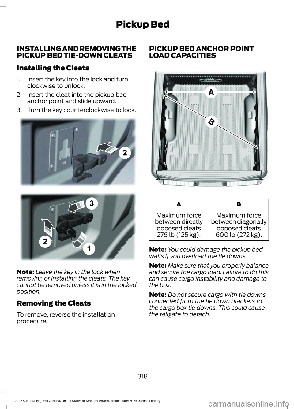
INSTALLING AND REMOVING THE
PICKUP BED TIE-DOWN CLEATS
Installing the Cleats
1. Insert the key into the lock and turn
clockwise to unlock.
2. Insert the cleat into the pickup bed anchor point and slide upward.
3. Turn the key counterclockwise to lock. Note:
Leave the key in the lock when
removing or installing the cleats. The key
cannot be removed unless it is in the locked
position.
Removing the Cleats
To remove, reverse the installation
procedure. PICKUP BED ANCHOR POINT
LOAD CAPACITIES
B
A
Maximum force
between diagonally opposed cleats
600 lb (272 kg).
Maximum force
between directly opposed cleats276 lb (125 kg).
Note: You could damage the pickup bed
walls if you overload the tie downs.
Note: Make sure that you properly balance
and secure the cargo load. Failure to do this
can cause cargo instability and damage to
the box.
Note: Do not secure cargo with tie downs
connected from the tie down brackets to
the cargo box tie downs. This could cause
the tailgate to detach.
318
2022 Super Duty (TFE) Canada/United States of America, enUSA, Edition date: 202103, First-Printing Pickup BedE327575 E327576
Page 322 of 740
TAILGATE ANCHOR POINTS (IF
EQUIPPED)
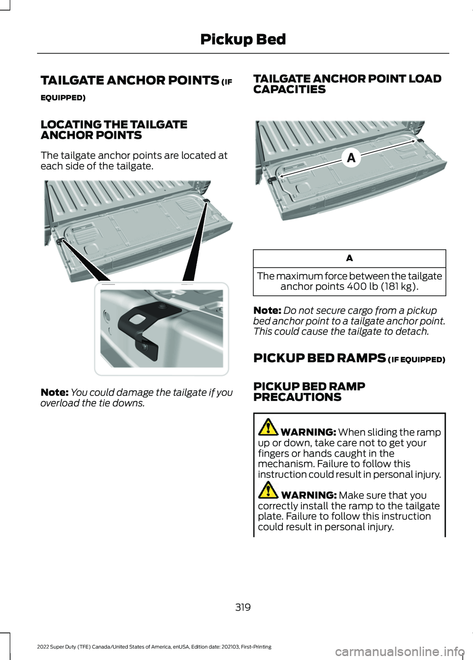
LOCATING THE TAILGATE
ANCHOR POINTS
The tailgate anchor points are located at
each side of the tailgate. Note:
You could damage the tailgate if you
overload the tie downs. TAILGATE ANCHOR POINT LOAD
CAPACITIES A
The maximum force between the tailgate anchor points
400 lb (181 kg).
Note: Do not secure cargo from a pickup
bed anchor point to a tailgate anchor point.
This could cause the tailgate to detach.
PICKUP BED RAMPS (IF EQUIPPED)
PICKUP BED RAMP
PRECAUTIONS WARNING:
When sliding the ramp
up or down, take care not to get your
fingers or hands caught in the
mechanism. Failure to follow this
instruction could result in personal injury. WARNING:
Make sure that you
correctly install the ramp to the tailgate
plate. Failure to follow this instruction
could result in personal injury.
319
2022 Super Duty (TFE) Canada/United States of America, enUSA, Edition date: 202103, First-Printing Pickup BedE327594 E327790
Page 323 of 740
WARNING: Do not step or sit on
the ramp when it is in the stowed
position. Failure to follow this instruction
could result in personal injury. WARNING:
Only install the ramp
within the prescribed ramp angles.
Failure to follow this instruction could
result in personal injury.
Note: Each pickup bed ramp has a
maximum capacity of
400 lb (181.4 kg).
Note: Verify the ramp is on stable ground
before usage.
Note: For loading and unloading
equipment, your ramp should be set
between 10 degrees upward and 26 degrees
downward to avoid damage to the ramp
claw and tailgate plate.
Note: When using your vehicle for off-road
operation, remove the bed ramps from the
vehicle and store them in a safe location
away from your vehicle.
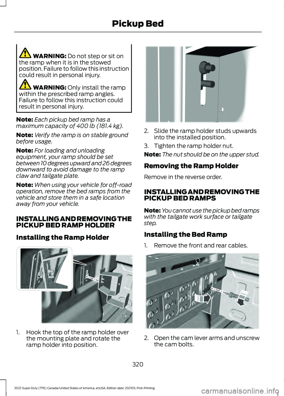
INSTALLING AND REMOVING THE
PICKUP BED RAMP HOLDER
Installing the Ramp Holder 1. Hook the top of the ramp holder over
the mounting plate and rotate the
ramp holder into position. 2. Slide the ramp holder studs upwards
into the installed position.
3. Tighten the ramp holder nut.
Note: The nut should be on the upper stud.
Removing the Ramp Holder
Remove in the reverse order.
INSTALLING AND REMOVING THE
PICKUP BED RAMPS
Note: You cannot use the pickup bed ramps
with the tailgate work surface or tailgate
step.
Installing the Bed Ramp
1. Remove the front and rear cables. 2.
Open the cam lever arms and unscrew
the cam bolts.
320
2022 Super Duty (TFE) Canada/United States of America, enUSA, Edition date: 202103, First-Printing Pickup BedE194387 E194388 E194380
Page 324 of 740
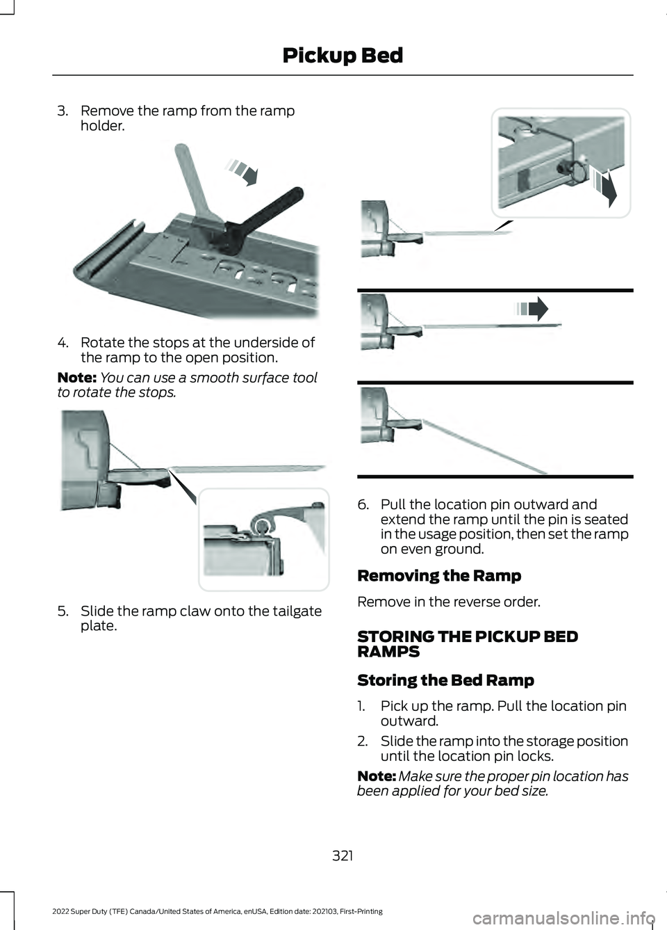
3. Remove the ramp from the ramp
holder. 4. Rotate the stops at the underside of
the ramp to the open position.
Note: You can use a smooth surface tool
to rotate the stops. 5. Slide the ramp claw onto the tailgate
plate. 6. Pull the location pin outward and
extend the ramp until the pin is seated
in the usage position, then set the ramp
on even ground.
Removing the Ramp
Remove in the reverse order.
STORING THE PICKUP BED
RAMPS
Storing the Bed Ramp
1. Pick up the ramp. Pull the location pin outward.
2. Slide the ramp into the storage position
until the location pin locks.
Note: Make sure the proper pin location has
been applied for your bed size.
321
2022 Super Duty (TFE) Canada/United States of America, enUSA, Edition date: 202103, First-Printing Pickup BedE211150 E194382 E194383
Page 325 of 740
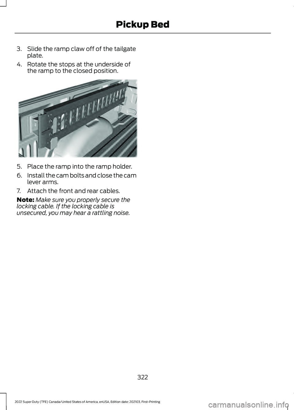
3. Slide the ramp claw off of the tailgate
plate.
4. Rotate the stops at the underside of the ramp to the closed position. 5. Place the ramp into the ramp holder.
6.
Install the cam bolts and close the cam
lever arms.
7. Attach the front and rear cables.
Note: Make sure you properly secure the
locking cable. If the locking cable is
unsecured, you may hear a rattling noise.
322
2022 Super Duty (TFE) Canada/United States of America, enUSA, Edition date: 202103, First-Printing Pickup BedE194391
Page 326 of 740
CONNECTING A TRAILER
PRECAUTIONS
WARNING: Do not adjust the spring
bars so that your vehicle's rear bumper
is higher than before attaching the trailer.
Doing so will defeat the function of the
weight-distributing hitch, which may
cause unpredictable handling, and could
result in serious personal injury.
Do not tow a trailer until you drive your
vehicle at least 1,000 mi (1,600 km).
Consult your local motor vehicle laws for
towing a trailer.
See the instructions included with towing
accessories for the proper installation and
adjustment specifications.
Service your vehicle more frequently if you
tow a trailer. See
Normal Scheduled
Maintenance (page 625).
If you use a rental trailer, follow the
instructions the rental agency gives you.
When attaching the trailer wiring connector
to your vehicle, only use a proper fitting
connector that works with the vehicle and
trailer functions.
Account for the trailer coupler weight as
part of your vehicle load when calculating
the total vehicle weight.
Do not exceed the load limits. See
Calculating the Load Limit
(page 314). HITCHES
INSTALLING A HITCH WARNING:
You must use the
heavy-duty drawbar pin supplied with
your vehicle when using the heavy-duty
hitch. Failure to follow this instruction
could result in the loss of control of your
vehicle, personal injury or death.
Do not use a hitch that either clamps onto
the bumper or attaches to the axle. You
must distribute the load in your trailer so
that 10-15% for conventional towing or
15-25% for fifth wheel towing of the total
weight of the trailer is on the tongue. Do
not exceed the tongue load rating
indicated on the conventional hitch
receiver.
Note: On pick-up trucks, the trailer hitch
provided on this vehicle enhances crash
protection for the fuel system. Do not
remove!
Hitch Components
The following components are required.
Some are provided in certain vehicles.
• A trailer hitch with a 3 inch receiver and
a 5/8 inch hitch pin. Check the
stamped rating number on the pin to
determine the
21,200 lb (9,616 kg) or
24,200 lb (10,976 kg) hitch pin
capacity.
• A hitch pin sleeve stored in the glove
box to use when mounting the 3 inch
drawbar with the 3/4 inch pin hole.
• A cotter pin to help keep the hitch pin
in place.
323
2022 Super Duty (TFE) Canada/United States of America, enUSA, Edition date: 202103, First-Printing Connecting a Trailer
Page 327 of 740
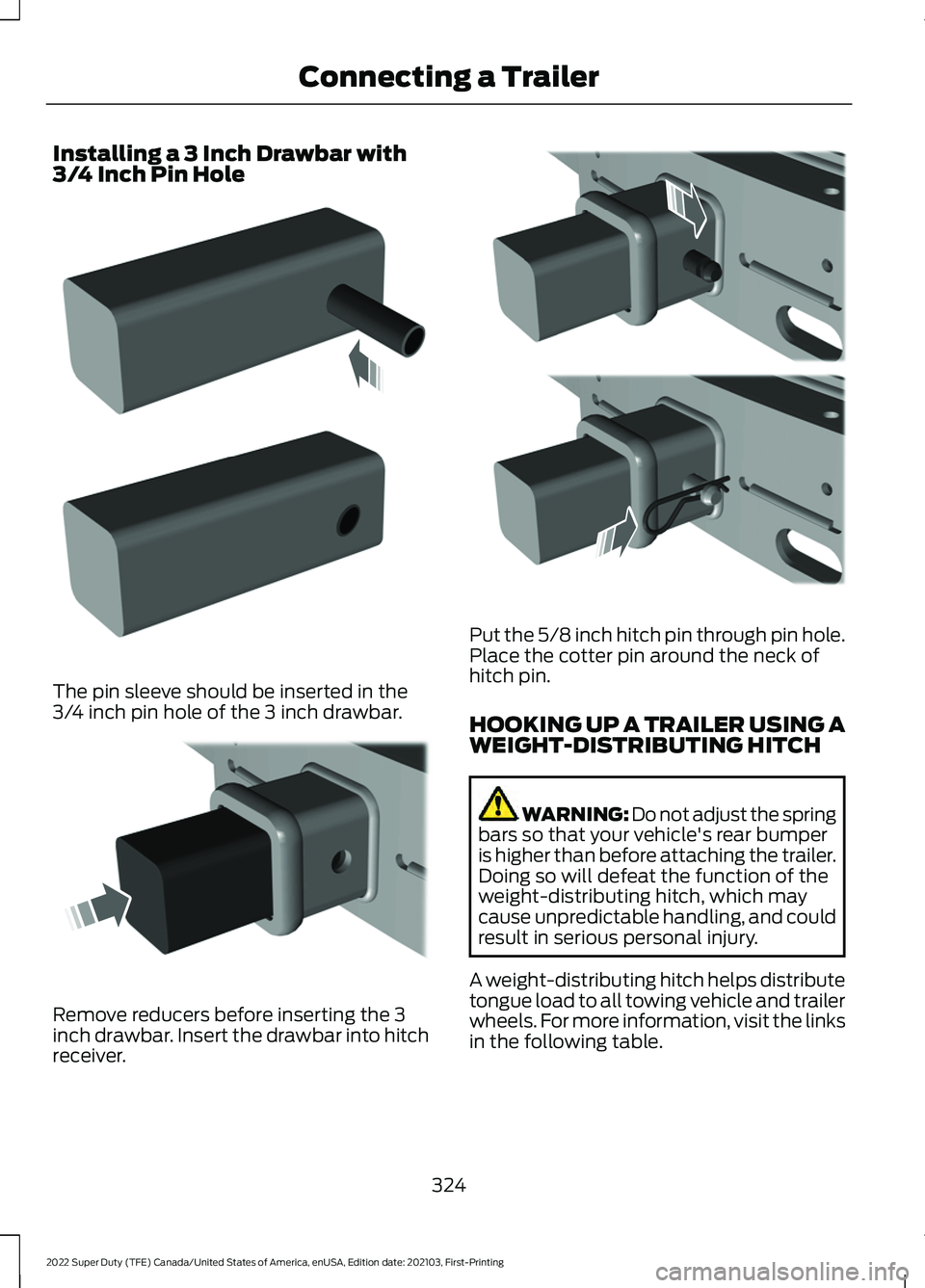
Installing a 3 Inch Drawbar with
3/4 Inch Pin Hole
The pin sleeve should be inserted in the
3/4 inch pin hole of the 3 inch drawbar.
Remove reducers before inserting the 3
inch drawbar. Insert the drawbar into hitch
receiver. Put the 5/8 inch hitch pin through pin hole.
Place the cotter pin around the neck of
hitch pin.
HOOKING UP A TRAILER USING A
WEIGHT-DISTRIBUTING HITCH
WARNING: Do not adjust the spring
bars so that your vehicle's rear bumper
is higher than before attaching the trailer.
Doing so will defeat the function of the
weight-distributing hitch, which may
cause unpredictable handling, and could
result in serious personal injury.
A weight-distributing hitch helps distribute
tongue load to all towing vehicle and trailer
wheels. For more information, visit the links
in the following table.
324
2022 Super Duty (TFE) Canada/United States of America, enUSA, Edition date: 202103, First-Printing Connecting a TrailerE247903 E247902 E247909
Page 328 of 740
Website
Market
ht tp s:/ /
www .fl e e t.f or d . c om/
t o wing-g uide s/United States of
America
ht tp s:/ /
www .fl e e t.f or d . c a/
t o wing-g uide s/Canada
FIFTH-WHEEL TRAILER HITCH
Your vehicle has a fifth-wheel prep
package. This package enables your
vehicle to accept certain fifth-wheel trailer
hitches and gooseneck ball hitches. The
fifth-wheel trailer hitch attaches to the four
mounting pads in the pick-up bed. A 7-pin
trailer wiring connector could be in the bed
as well. The gooseneck ball hitch is a
separate mounting pad from the
fifth-wheel hitch in the center of the bed.
Shorter pick-up boxes provide less
clearance between the cab and the
fifth-wheel and gooseneck trailer
compared to longer box pick-ups. When
selecting a trailer and tow vehicle, it is
critical to check that this combination
provides clearance between the front of
the trailer and tow vehicle for turns up to
90°. Failure to follow this recommendation
could result in the trailer contacting the
cab of the tow vehicle during tight turns
that are typical during low-speed parking
and turning maneuvers. This contact could
result in damage to the trailer and tow
vehicle.
Note: Contact an authorized dealer to
purchase gooseneck and fifth-wheel hitches
that are compatible with your vehicle.
Note: The mounting pads in the bed are
specifically designed for certain fifth-wheel
trailer hitches and gooseneck ball hitches.
Do not use these mounting pads for other
purposes. CONNECTING A TRAILER
Recognizing a Trailer
1.
Attach the trailer and wiring connector
to your vehicle.
2. Switch on your vehicle.
3. Set up a profile for the trailer using the
instrument cluster display.
Note: If your vehicle does not recognize the
trailer, press and hold the brake pedal for a
few seconds.
Note: Trailer profiles store trailer types,
dimensions, preferences, trailer specific
mileage and fuel economy.
Note: Disabling the trailer detection
notification makes the default trailer profile
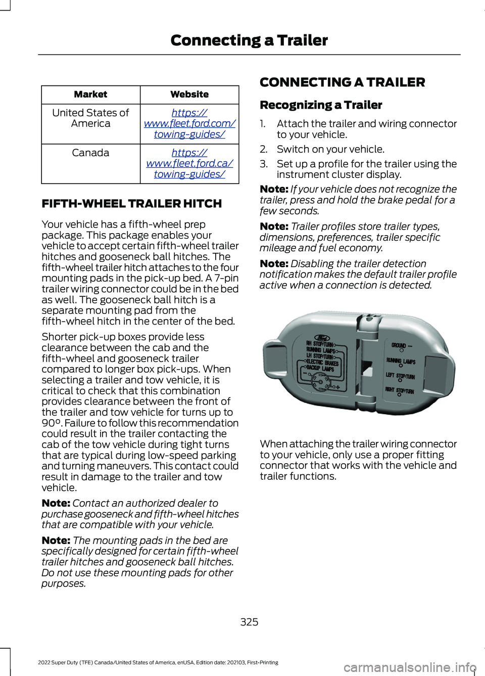
active when a connection is detected. When attaching the trailer wiring connector
to your vehicle, only use a proper fitting
connector that works with the vehicle and
trailer functions.
325
2022 Super Duty (TFE) Canada/United States of America, enUSA, Edition date: 202103, First-Printing Connecting a TrailerE163167
Page 329 of 740
Trailer Light Check
WARNING: Never connect any
trailer lamp wiring to the vehicle's tail
lamp wiring; this may damage the
electrical system resulting in fire. Contact
your authorized dealer as soon as
possible for assistance in proper trailer
tow wiring installation. Additional
electrical equipment may be required.
Most towed vehicles require trailer lamps.
Make sure all running lights, brake lights,
turn signals and hazard lights are working.
Safety Chains
Install trailer safety chains to the trailer
hitch as recommended by the
manufacturer. Cross the chains under the
trailer coupler and allow enough slack for
turning tight corners. Do not allow the
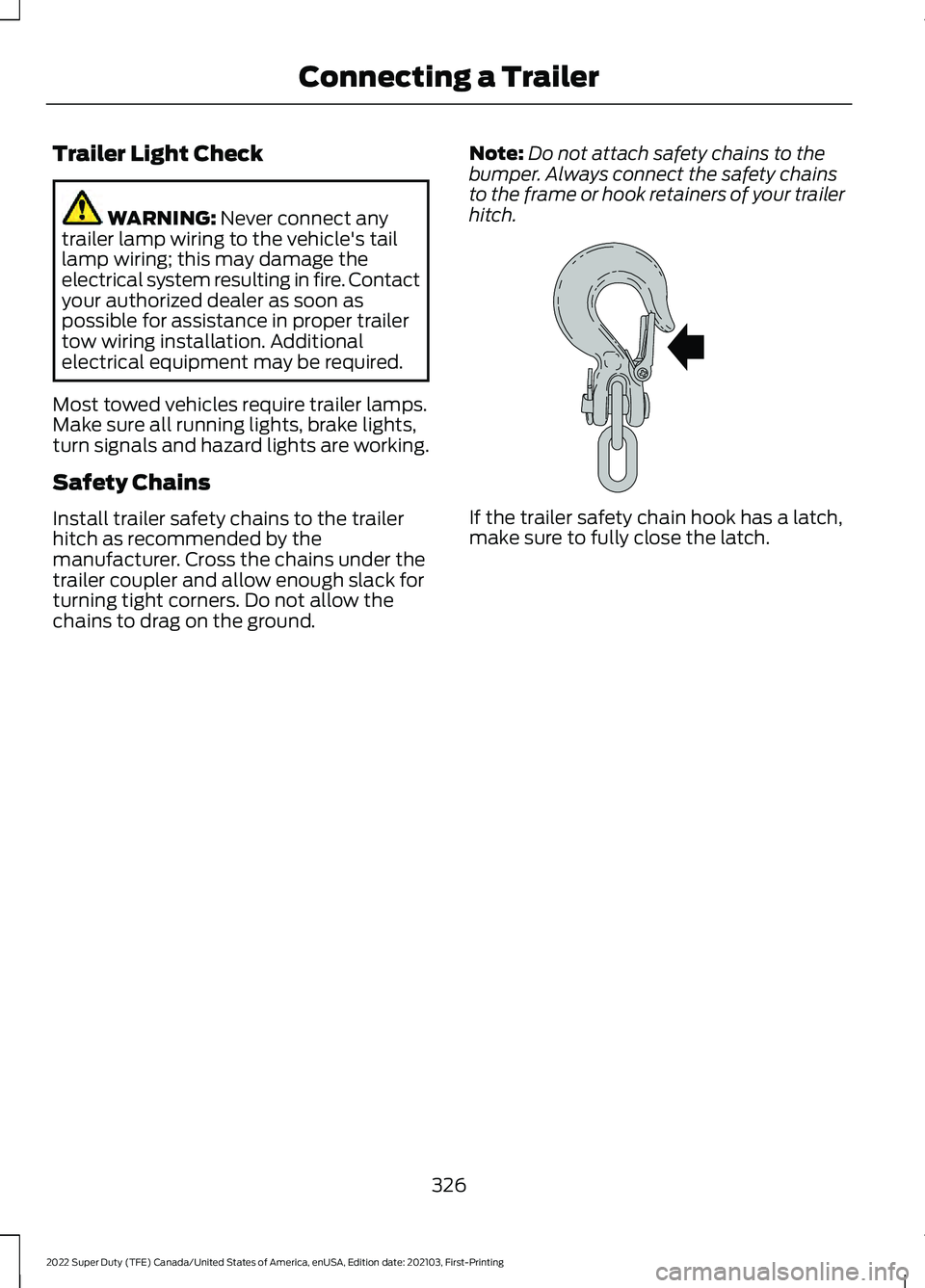
chains to drag on the ground. Note:
Do not attach safety chains to the
bumper. Always connect the safety chains
to the frame or hook retainers of your trailer
hitch. If the trailer safety chain hook has a latch,
make sure to fully close the latch.
326
2022 Super Duty (TFE) Canada/United States of America, enUSA, Edition date: 202103, First-Printing Connecting a TrailerE265060
Page 330 of 740
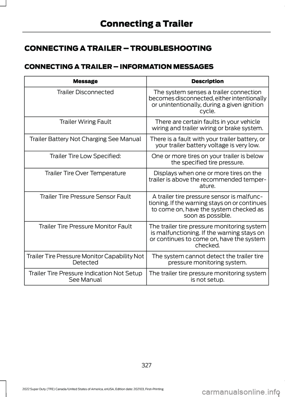
CONNECTING A TRAILER – TROUBLESHOOTING
CONNECTING A TRAILER – INFORMATION MESSAGES
Description
Message
The system senses a trailer connection
becomes disconnected, either intentionally or unintentionally, during a given ignition cycle.
Trailer Disconnected
There are certain faults in your vehicle
wiring and trailer wiring or brake system.
Trailer Wiring Fault
There is a fault with your trailer battery, oryour trailer battery voltage is very low.
Trailer Battery Not Charging See Manual
One or more tires on your trailer is belowthe specified tire pressure.
Trailer Tire Low Specified:
Displays when one or more tires on the
trailer is above the recommended temper- ature.
Trailer Tire Over Temperature
A trailer tire pressure sensor is malfunc-
tioning. If the warning stays on or continues to come on, have the system checked as soon as possible.
Trailer Tire Pressure Sensor Fault
The trailer tire pressure monitoring systemis malfunctioning. If the warning stays on
or continues to come on, have the system checked.
Trailer Tire Pressure Monitor Fault
The system cannot detect the trailer tirepressure monitoring system.
Trailer Tire Pressure Monitor Capability Not
Detected
The trailer tire pressure monitoring systemis not setup.
Trailer Tire Pressure Indication Not Setup
See Manual
327
2022 Super Duty (TFE) Canada/United States of America, enUSA, Edition date: 202103, First-Printing Connecting a Trailer