Torque FORD F-550 2021 Owners Manual
[x] Cancel search | Manufacturer: FORD, Model Year: 2021, Model line: F-550, Model: FORD F-550 2021Pages: 666, PDF Size: 11.3 MB
Page 217 of 666
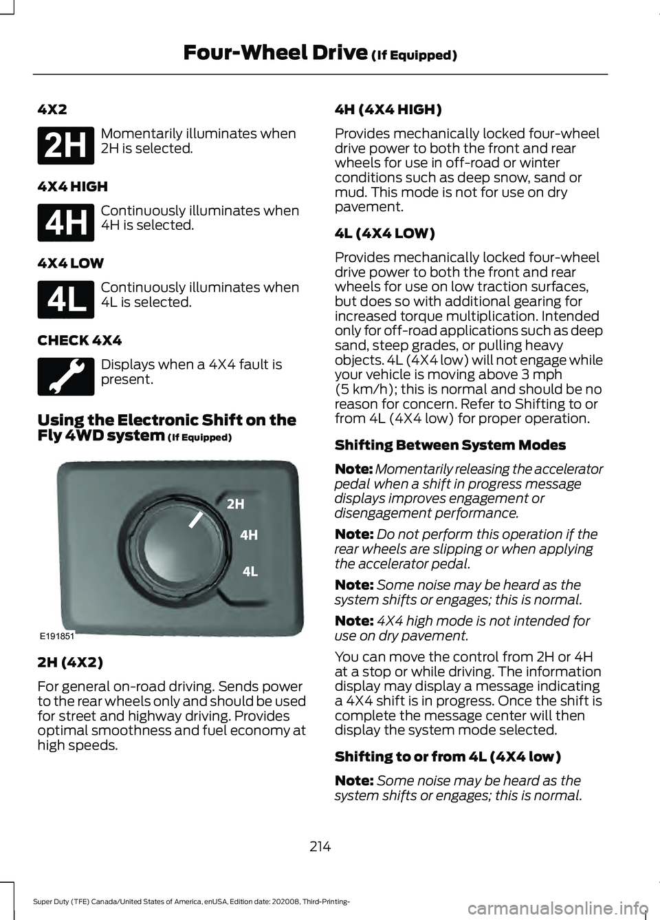
4X2
Momentarily illuminates when
2H is selected.
4X4 HIGH Continuously illuminates when
4H is selected.
4X4 LOW Continuously illuminates when
4L is selected.
CHECK 4X4 Displays when a 4X4 fault is
present.
Using the Electronic Shift on the
Fly 4WD system (If Equipped) 2H (4X2)
For general on-road driving. Sends power
to the rear wheels only and should be used
for street and highway driving. Provides
optimal smoothness and fuel economy at
high speeds. 4H (4X4 HIGH)
Provides mechanically locked four-wheel
drive power to both the front and rear
wheels for use in off-road or winter
conditions such as deep snow, sand or
mud. This mode is not for use on dry
pavement.
4L (4X4 LOW)
Provides mechanically locked four-wheel
drive power to both the front and rear
wheels for use on low traction surfaces,
but does so with additional gearing for
increased torque multiplication. Intended
only for off-road applications such as deep
sand, steep grades, or pulling heavy
objects. 4L (4X4 low) will not engage while
your vehicle is moving above
3 mph
(5 km/h); this is normal and should be no
reason for concern. Refer to Shifting to or
from 4L (4X4 low) for proper operation.
Shifting Between System Modes
Note: Momentarily releasing the accelerator
pedal when a shift in progress message
displays improves engagement or
disengagement performance.
Note: Do not perform this operation if the
rear wheels are slipping or when applying
the accelerator pedal.
Note: Some noise may be heard as the
system shifts or engages; this is normal.
Note: 4X4 high mode is not intended for
use on dry pavement.
You can move the control from 2H or 4H
at a stop or while driving. The information
display may display a message indicating
a 4X4 shift is in progress. Once the shift is
complete the message center will then
display the system mode selected.
Shifting to or from 4L (4X4 low)
Note: Some noise may be heard as the
system shifts or engages; this is normal.
214
Super Duty (TFE) Canada/United States of America, enUSA, Edition date: 202008, Third-Printing- Four-Wheel Drive
(If Equipped)E181778 E181779 E181780 E191851
Page 229 of 666
When the system is active, your vehicle
remains stationary on the slope for two to
three seconds after you release the brake
pedal. This allows time to move your foot
from the brake to the accelerator pedal.
The system releases the brakes
automatically once the engine has
developed sufficient torque to prevent your
vehicle from rolling down the slope. This
is an advantage when pulling away on a
slope, for example from a car park ramp,
traffic lights or when reversing uphill into
a parking space.
The system activates on any slope that
causes your vehicle to roll.
Note:
There is no warning light to indicate
the system is either on or off.
Using Hill Start Assist
1. Press the brake pedal to bring your vehicle to a complete standstill. Keep
the brake pedal pressed and shift into
first gear when facing uphill or reverse
(R) when facing downhill.
2. If the sensors detect that your vehicle is on a slope, the system activates
automatically.
3. When you remove your foot from the brake pedal, your vehicle remains on
the slope without rolling away for
about two to three seconds. This hold
time automatically extends if you are
in the process of driving off.
4. Drive off in the normal manner. The system releases the brakes
automatically.
Note: When you remove your foot from the
brake pedal and press the pedal again when
the system is active, you will experience
significantly reduced brake pedal travel. This
is normal. Switching the System On and Off
Vehicles with Manual Transmission
You can switch this feature on or off in the
information display. The system
remembers the last setting when you start
your vehicle.
Vehicles with Automatic Transmission
You cannot turn the system on or off.
When you switch the ignition on, the
system automatically turns on.
226
Super Duty (TFE) Canada/United States of America, enUSA, Edition date: 202008, Third-Printing- Brakes
Page 265 of 666
STEERING
Hydraulic Power Steering
To help prevent damage to the power
steering system:
•
Do not hold the steering wheel at its
furthest turning points for more than
three to five seconds when the engine
is running.
• Avoid continuously steering back and
forth with elevated engine RPM as this
may overheat the system. If trying to
free a stuck vehicle, pause between
attempts to allow the power steering
system to cool or seek assistance.
Typical steering and driving maneuvers
allow the system to cool.
• Do not operate the vehicle if the power
steering pump fluid level is below the
MIN mark on the reservoir.
• Some noise is normal during operation.
If excessive, check for low power
steering pump fluid level before
seeking service by your dealer.
• Heavy or uneven efforts may be caused
by low power steering fluid. Check for
low power steering pump fluid level
before seeking service by your dealer.
• Do not fill the power steering pump
reservoir above the MAX mark on the
reservoir, as this may result in leaks
from the reservoir.
If the power steering system breaks down
or if you switch the engine off, you can
steer the vehicle manually, but it takes
more effort.
If you have any steering components
serviced or replaced, install new fasteners.
Many fasteners have coatings with thread
adhesive, or have prevailing torque
features you cannot reuse. Do not reuse a
bolt or nut. Torque fasteners to
specifications. Steering Tips
If the steering wanders or pulls, check for:
•
An improperly inflated tire.
• Uneven tire wear.
• Loose or worn suspension
components.
• Loose or worn steering components.
• Improper vehicle alignment.
Note: A high crown in the road or high
crosswinds may also make the steering
seem to wander or pull.
Electronic Torque Overlay Steering
(If Equipped) WARNING: The electric power
steering system has diagnostic checks
that continuously monitor the system. If
a fault is detected, a message displays
in the information display. Stop your
vehicle as soon as it is safe to do so.
Switch the ignition off. After at least 10
seconds, switch the ignition on and
watch the information display for a
steering system warning message. If a
steering system warning message
returns, have the system checked as
soon as possible. WARNING:
If the system detects
an error, you may not feel a difference in
the steering, however a serious condition
may exist. Have your vehicle checked as
soon as possible. Failure to do so may
result in loss of steering control.
262
Super Duty (TFE) Canada/United States of America, enUSA, Edition date: 202008, Third-Printing- Driving Aids
Page 266 of 666
The electronic torque overlay steering
system adds supplemental steering assist
to the hydraulic gear when needed,
dependent on vehicle conditions such as
vehicle speed, steering wheel angle, and
steering wheel torque. The hydraulic
steering system provides the majority of
steering assistance. The electronic torque
overlay enables features such as pro trailer
backup assistance and lane departure
warning.
If your vehicle loses electrical power while
you are driving, your vehicle loses electric
power steering assistance. The steering
system still operates, and you can steer
your vehicle with hydraulic assist. Steering
your vehicle with only hydraulic assist
requires more effort.
Extreme continuous steering may increase
the effort required for you to steer your
vehicle. This increased effort prevents
overheating and permanent damage to
the steering system. You do not lose the
ability to steer your vehicle manually.
Typical steering and driving maneuvers
allow the system to cool and return to
normal operation.
Adaptive Learning (If Equipped)
The electronic power steering system
adaptive learning helps correct road
irregularities and improves overall handling
and steering feel. It communicates with
the brake system to help operate
advanced stability control and accident
avoidance systems. Whenever the battery
is disconnected or a new battery installed,
you must drive your vehicle a short
distance before the system relearns the
strategy and reactivates all systems. Adaptive Steering
(If Equipped)
Note: The adaptive steering system has
diagnostic checks that continuously monitor
the system. If the system detects a fault, a
message displays in the information display.
If a red warning message displays, stop your
vehicle as soon as it is safe to do so. The
message may clear if the fault is no longer
present. If an adaptive steering system
warning message appears each time you
start your vehicle, have the system checked
as soon as possible.
The adaptive steering system continually
changes the steering ratio with changes to
vehicle speed, optimizing the steering
response in all conditions. The system also
changes when you switch on the
transmission tow/haul feature. When you
select the tow/haul button, the adaptive
steering system reduces vehicle sensitivity
to steering inputs at higher vehicle speeds,
while maintaining the ease of parking and
maneuverability at low speeds.
Note: The adaptive steering system is
designed with a locking device. With the
lock engaged, the adaptive steering system
remains mechanically locked at a fixed
steering ratio. You may also notice a click
when you switch the vehicle on or after you
switch it off, as the lock disengages or
engages.
Note: If your vehicle loses electrical power
or detects a fault when you are driving, the
system automatically shuts down and you
retain normal steering function with a fixed
steering ratio. During this time it is possible
that the steering wheel may not be straight
when the vehicle is driving straight ahead.
In addition, the driver may notice that the
steering wheel angle required to steer the
vehicle may be different.
263
Super Duty (TFE) Canada/United States of America, enUSA, Edition date: 202008, Third-Printing- Driving Aids
Page 323 of 666
•
Inspect exhaust system for damage or
looseness.
• Inspect undercarriage fasteners. If any
are loose or damaged, tighten or
replace ensuring that the proper torque
specification is used.
• Inspect the tires for any cuts in the
tread or sidewall area. Also inspect the
sidewall for any bulge indicating
damage to the tire.
• Inspect the wheels for dents, cracks,
or other damage.
• Refit the front license plate if removed
previously.
BREAKING-IN
You need to break in new tires for
approximately 300 mi (480 km). During
this time, your vehicle may exhibit some
unusual driving characteristics.
Avoid driving too fast during the first
1,000 mi (1,600 km)
. Vary your speed
frequently and change up through the
gears early. Do not labor the engine.
Drive your new vehicle at least
1,000 mi
(1,600 km) before towing a trailer. Make
sure you use the specified engine oil. See
Engine Oil Capacity and Specification
(page
449).
Do not add friction modifier compounds
or special break-in oils during the first few
thousand miles (kilometers) of operation.
These additives may prevent piston ring
seating.
DRIVING THROUGH WATER WARNING:
Do not drive through
flowing or deep water as you may lose
control of your vehicle. Note:
Engine damage can occur if water
enters the air filter.
For Vehicles without Tremor Off-
Road Package
Note: Driving through standing water can
cause vehicle damage.
Note: Drive through water in an emergency
only and not as part of normal driving.
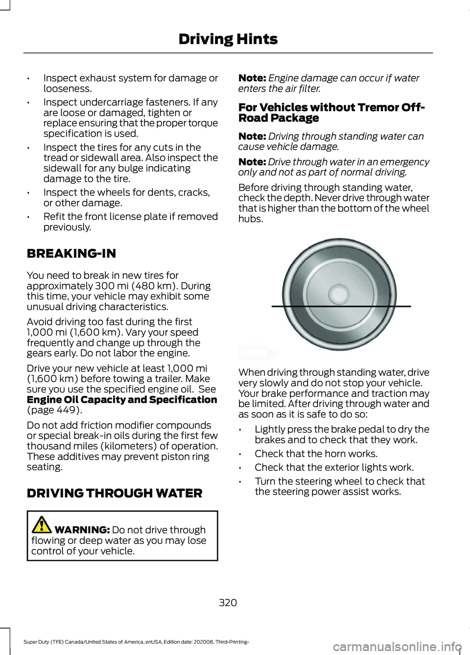
Before driving through standing water,
check the depth. Never drive through water
that is higher than the bottom of the wheel
hubs. When driving through standing water, drive
very slowly and do not stop your vehicle.
Your brake performance and traction may
be limited. After driving through water and
as soon as it is safe to do so:
•
Lightly press the brake pedal to dry the
brakes and to check that they work.
• Check that the horn works.
• Check that the exterior lights work.
• Turn the steering wheel to check that
the steering power assist works.
320
Super Duty (TFE) Canada/United States of America, enUSA, Edition date: 202008, Third-Printing- Driving HintsE176913
Page 343 of 666
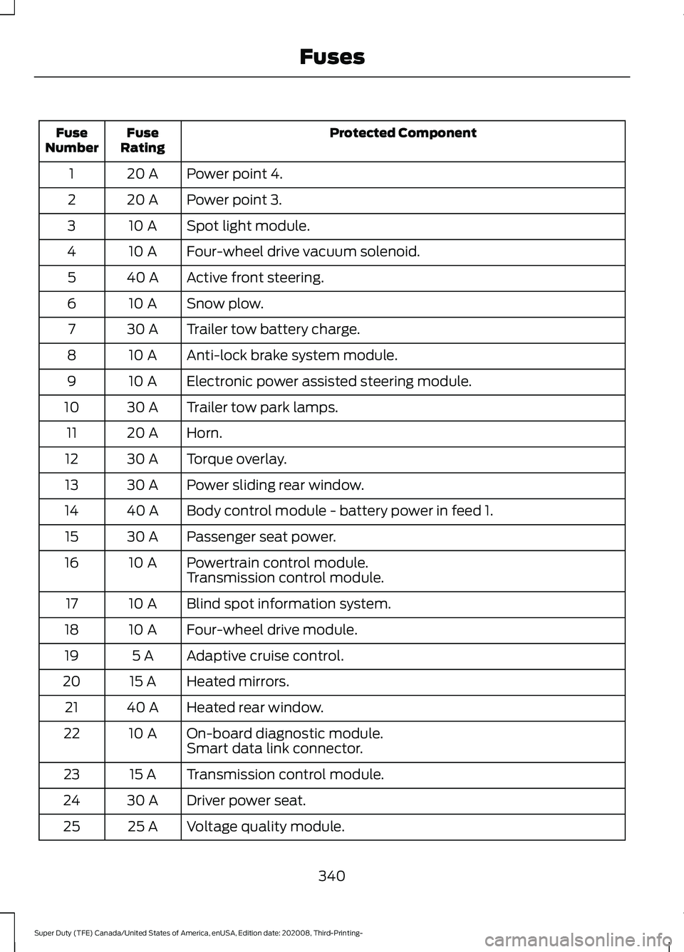
Protected Component
Fuse
Rating
Fuse
Number
Power point 4.
20 A
1
Power point 3.
20 A
2
Spot light module.
10 A
3
Four-wheel drive vacuum solenoid.
10 A
4
Active front steering.
40 A
5
Snow plow.
10 A
6
Trailer tow battery charge.
30 A
7
Anti-lock brake system module.
10 A
8
Electronic power assisted steering module.
10 A
9
Trailer tow park lamps.
30 A
10
Horn.
20 A
11
Torque overlay.
30 A
12
Power sliding rear window.
30 A
13
Body control module - battery power in feed 1.
40 A
14
Passenger seat power.
30 A
15
Powertrain control module.
10 A
16
Transmission control module.
Blind spot information system.
10 A
17
Four-wheel drive module.
10 A
18
Adaptive cruise control.
5 A
19
Heated mirrors.
15 A
20
Heated rear window.
40 A
21
On-board diagnostic module.
10 A
22
Smart data link connector.
Transmission control module.
15 A
23
Driver power seat.
30 A
24
Voltage quality module.
25 A
25
340
Super Duty (TFE) Canada/United States of America, enUSA, Edition date: 202008, Third-Printing- Fuses
Page 391 of 666

3. Drain the diesel fuel conditioner
module. Turn the drain plug
counterclockwise until it stops. Do not
use any tools to loosen the drain plug.
Drain the filter, approximately 0.53 gal
(2 L), into an appropriate container.
Do not re-use the fuel drained from the
module. 4. Disconnect the electrical connector.
5. Fully loosen the bolts securing the
lower portion of the diesel fuel
conditioner module housing.
Note: Do not fully remove the bolts from
the lower portion of the diesel fuel
conditioner module housing.
6. Remove the lower portion of the diesel
fuel conditioner module housing. 7. Slide the filter element toward the
drain plug to disengage the securing
clips.
Installation
1. Slide the filter element into the housing
and fully engage the securing clips.
2. Install the lower portion of the housing.
Tighten the bolts until you feel a strong
resistance. Maximum torque
7 lb.ft
(9 Nm).
3. Connect the electrical connector.
4. Tighten the drain plug, turn it clockwise
until it stops and you feel a strong
resistance. Do not use any tools to
tighten the drain plug.
388
Super Duty (TFE) Canada/United States of America, enUSA, Edition date: 202008, Third-Printing- MaintenanceE269861 E269862 E269863
Page 393 of 666
Check and tighten the U-bolt nuts with
your vehicle at curb height and unloaded.
Inspect the U-bolt threads for rust and
debris. Clean the threads if contaminated.
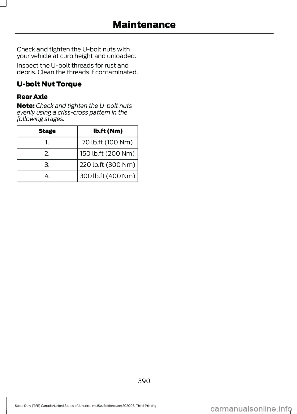
U-bolt Nut Torque
Rear Axle
Note:
Check and tighten the U-bolt nuts
evenly using a criss-cross pattern in the
following stages. lb.ft (Nm)
Stage
70 lb.ft (100 Nm)
1.
150 lb.ft (200 Nm)
2.
220 lb.ft (300 Nm)
3.
300 lb.ft (400 Nm)
4.
390
Super Duty (TFE) Canada/United States of America, enUSA, Edition date: 202008, Third-Printing- Maintenance
Page 440 of 666
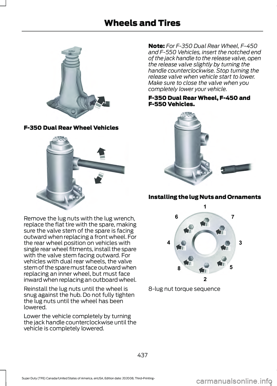
F-350 Dual Rear Wheel Vehicles
Remove the lug nuts with the lug wrench,
replace the flat tire with the spare, making
sure the valve stem of the spare is facing
outward when replacing a front wheel. For
the rear wheel position on vehicles with
single rear wheel fitments, install the spare
with the valve stem facing outward. For
vehicles with dual rear wheels, the valve
stem of the spare must face outward when
replacing an inner wheel, but must face
inward when replacing an outboard wheel.
Reinstall the lug nuts until the wheel is
snug against the hub. Do not fully tighten
the lug nuts until the wheel has been
lowered.
Lower the vehicle completely by turning
the jack handle counterclockwise until the
vehicle is completely lowered. Note:
For F-350 Dual Rear Wheel, F-450
and F-550 Vehicles, insert the notched end
of the jack handle to the release valve, open
the release valve slightly by turning the
handle counterclockwise. Stop turning the
release valve when vehicle start to lower.
Make sure to close the valve when you
completely lower your vehicle.
F-350 Dual Rear Wheel, F-450 and
F-550 Vehicles. Installing the lug Nuts and Ornaments
8-lug nut torque sequence
437
Super Duty (TFE) Canada/United States of America, enUSA, Edition date: 202008, Third-Printing- Wheels and TiresE162811 E162819 E162812 13
4
27
6
5
8E161441
Page 441 of 666
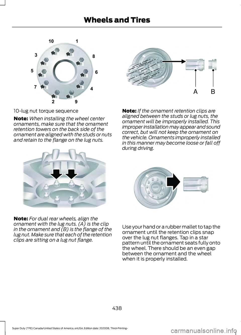
10-lug nut torque sequence
Note:
When installing the wheel center
ornaments, make sure that the ornament
retention towers on the back side of the
ornament are aligned with the studs or nuts
and retain to the flange on the lug nuts. Note:
For dual rear wheels, align the
ornament with the lug nuts. (A) is the clip
in the ornament and (B) is the flange of the
lug nut. Make sure that each of the retention
clips are sitting on a lug nut flange. Note:
If the ornament retention clips are
aligned between the studs or lug nuts, the
ornament will be improperly installed. This
improper installation may appear and sound
correct, but will not keep the ornament on
the vehicle. Ornaments improperly installed
in this manner may become loose or fall off
during driving. Use your hand or a rubber mallet to tap the
ornament until the retention clips snap
over the lug nut flanges. Tap in a star
pattern until the ornament seats fully onto
the wheel. There should be an even gap
between the ornament and the wheel
when it is properly installed.
438
Super Duty (TFE) Canada/United States of America, enUSA, Edition date: 202008, Third-Printing- Wheels and Tires1
2
3
4
5
6
7 8
9
10E169375 E162820 ABE162822 E162823