tailgate FORD F-600 2022 Owner's Manual
[x] Cancel search | Manufacturer: FORD, Model Year: 2022, Model line: F-600, Model: FORD F-600 2022Pages: 740, PDF Size: 12.6 MB
Page 141 of 740
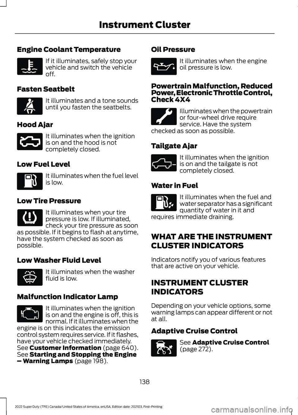
Engine Coolant Temperature
If it illuminates, safely stop your
vehicle and switch the vehicle
off.
Fasten Seatbelt It illuminates and a tone sounds
until you fasten the seatbelts.
Hood Ajar It illuminates when the ignition
is on and the hood is not
completely closed.
Low Fuel Level It illuminates when the fuel level
is low.
Low Tire Pressure It illuminates when your tire
pressure is low. If illuminated,
check your tire pressure as soon
as possible. If it begins to flash at anytime,
have the system checked as soon as
possible.
Low Washer Fluid Level It illuminates when the washer
fluid is low.
Malfunction Indicator Lamp It illuminates when the ignition
is on and the engine is off, this is
normal. If it illuminates when the
engine is on this indicates the emission
control system requires service. If it flashes,
have your vehicle checked immediately.
See Customer Information (page 640).
See Starting and Stopping the Engine
– Warning Lamps (page 198). Oil Pressure It illuminates when the engine
oil pressure is low.
Powertrain Malfunction, Reduced
Power, Electronic Throttle Control,
Check 4X4 Illuminates when the powertrain
or four-wheel drive require
service. Have the system
checked as soon as possible.
Tailgate Ajar It illuminates when the ignition
is on and the tailgate is not
completely closed.
Water in Fuel It illuminates when the fuel and
water separator has a significant
quantity of water in it and
requires immediate draining.
WHAT ARE THE INSTRUMENT
CLUSTER INDICATORS
Indicators notify you of various features
that are active on your vehicle.
INSTRUMENT CLUSTER
INDICATORS
Depending on your vehicle options, some
warning lamps can appear different or not
at all.
Adaptive Cruise Control See
Adaptive Cruise Control
(page 272).
138
2022 Super Duty (TFE) Canada/United States of America, enUSA, Edition date: 202103, First-Printing Instrument Cluster E71880 E296055 E132353 E324523 E144524
Page 263 of 740
PARKING AID PRECAUTIONS
WARNING: To help avoid personal
injury, always use caution when in
reverse (R) and when using the sensing
system. WARNING:
The system may not
detect objects with surfaces that absorb
reflection. Always drive with due care
and attention. Failure to take care may
result in a crash. WARNING: Traffic control systems,
fluorescent lamps, inclement weather,
air brakes, external motors and fans may
affect the correct operation of the
sensing system. This may cause reduced
performance or false alerts. WARNING:
The system may not
detect small or moving objects,
particularly those close to the ground. WARNING:
The parking aid system
can only assist you to detect objects
when your vehicle is moving at parking
speeds. To help avoid personal injury you
must take care when using the parking
aid system. WARNING:
The system may not
function if the sensor is blocked. WARNING:
In cold and severe
weather conditions the system may not
function. Rain, snow and spray can all
limit sensor performance. WARNING:
If damage occurs in the
immediate area surrounding the sensor,
have your vehicle checked as soon as
possible. Note:
If your vehicle sustains damage
leaving the sensors misaligned, this will
cause inaccurate measurements or false
alerts.
When you connect a trailer to your vehicle,
the rear parking aid detects the trailer and
provides an alert. Disable the parking aid
when you connect a trailer to prevent the
alert.
Note: Certain add-on devices installed
around the bumper or fascia may create
false alerts, for example, large trailer
hitches, bike or surfboard racks, license plate
brackets, bumper covers or any other device
that could block the normal detection zone
of the parking aid system. Aftermarket spare
tires or spare tire covers mounted to the rear
tailgate could cause false alerts from the
park aid system. Remove the add-on device
to prevent false alerts.
Note: Keep the sensors free from snow, ice
and large accumulations of dirt. If the
sensors are covered, the system's accuracy
can be affected.
Do not clean the sensors with sharp
objects.
Note: When using a programmed MyKey
you cannot switch this off. See
MyKey ™
(page 77).
REAR PARKING AID
WHAT IS THE REAR PARKING AID
Rear parking sensors detect objects behind
your vehicle when in reverse (R).
REAR PARKING AID LIMITATIONS
There is a decreased coverage area at the
outer corners.
When using a programmed MyKey, you
cannot switch the rear parking aid off.
260
2022 Super Duty (TFE) Canada/United States of America, enUSA, Edition date: 202103, First-Printing Parking Aids
(If Equipped)
Page 266 of 740
WHAT IS THE REAR VIEW
CAMERA
The rear view camera provides a video
image of the area behind your vehicle when
the transmission is in reverse (R).
The rear view camera button is
on the instrument panel.
REAR VIEW CAMERA
PRECAUTIONS WARNING: The rear view camera
system is a reverse aid supplement
device that still requires the driver to use
it in conjunction with the interior and
exterior mirrors for maximum coverage. WARNING:
Objects that are close
to either corner of the bumper or under
the bumper, might not be seen on the
screen due to the limited coverage of the
camera system. WARNING:
Reverse your vehicle
slowly. Failure to follow this instruction
could result in the loss of control of your
vehicle, personal injury or death. WARNING:
Use caution when the
tailgate is ajar. If the tailgate is ajar, the
camera is out of position and the video
image could be incorrect. All guide lines
disappear when the tailgate is ajar.
Failure to follow this instruction could
result in personal injury. WARNING:
Use caution when
turning camera features on or off when
the transmission is not in park (P). Make
sure your vehicle is not moving. Note:
When towing, the camera only sees
what you are towing. This might not provide
adequate coverage and you might not see
some objects. In some vehicles, the guide
lines may disappear when you connect the
trailer tow connector.
LOCATING THE REAR VIEW
CAMERA
The rear view camera is on the tailgate. It
provides a video image of the area behind
your vehicle.
263
2022 Super Duty (TFE) Canada/United States of America, enUSA, Edition date: 202103, First-Printing Rear View CameraE332186
Page 269 of 740
WHAT IS THE 360 DEGREE
CAMERA
The 360 degree camera system consists
of front, side and rear cameras which
provide visibility around your vehicle.
HOW DOES THE 360 DEGREE
CAMERA WORK
The 360 Degree Camera system:
•
Allows you to see what is directly in
front of or behind your vehicle.
• Helps you when parallel parking and
centering in a parking space.
• Provides a cross traffic view in front of
and behind your vehicle.
• Allows you to see a top-down view of
the area outside your vehicle, including
the blind spots and obstacles near your
vehicle.
360 DEGREE CAMERA
PRECAUTIONS WARNING: The 360 degree
camera system still requires the driver
to use it in conjunction with looking out
of the windows, and checking the interior
and exterior mirrors for maximum
coverage. WARNING:
Objects that are close
to either corner of the bumper or under
the bumper, might not be seen on the
screen due to the limited coverage of the
camera system. WARNING:
Use caution when
turning camera features on or off when
the transmission is not in park (P). Make
sure your vehicle is not moving. WARNING: You are responsible for
controlling your vehicle at all times. The
system is designed to be an aid and does
not relieve you of your responsibility to
drive with due care and attention. Failure
to follow this instruction could result in
the loss of control of your vehicle,
personal injury or death.
360 DEGREE CAMERA
LIMITATIONS
Note: Use caution if a door is ajar. The 360
degree camera could be out of position and
the image could be incorrect.
LOCATING THE 360 DEGREE
CAMERAS
Rear View Camera
The rear view camera is on the tailgate. It
provides a video image of the area behind
your vehicle.
Front View Camera
The front view camera is in the grille. It
provides a video image of the area in front
of your vehicle.
Side View Camera
The side view camera is on the outside
mirror. It provides a video image of the area
on the sides of your vehicle to aid you when
parking or when backing up a trailer.
266
2022 Super Duty (TFE) Canada/United States of America, enUSA, Edition date: 202103, First-Printing 360 Degree Camera
(If Equipped)
Page 321 of 740
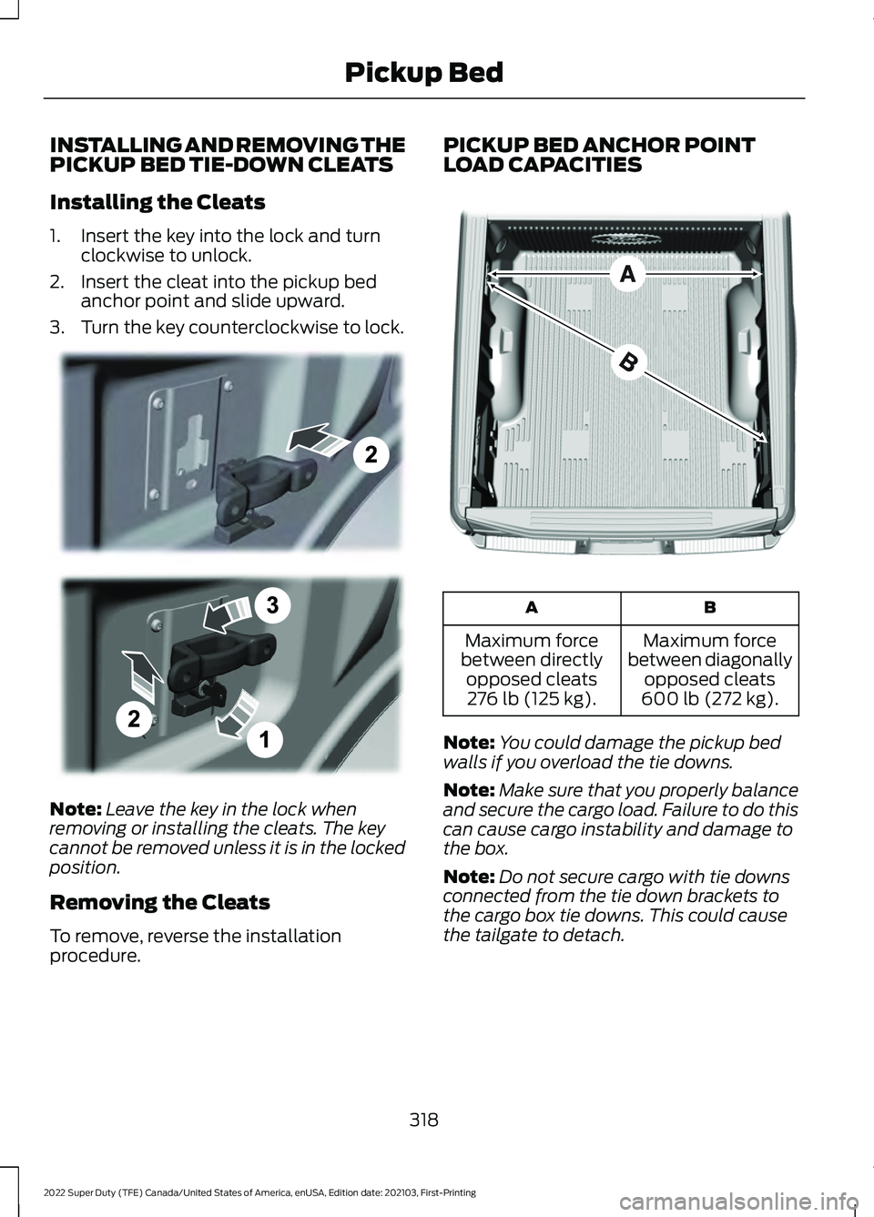
INSTALLING AND REMOVING THE
PICKUP BED TIE-DOWN CLEATS
Installing the Cleats
1. Insert the key into the lock and turn
clockwise to unlock.
2. Insert the cleat into the pickup bed anchor point and slide upward.
3. Turn the key counterclockwise to lock. Note:
Leave the key in the lock when
removing or installing the cleats. The key
cannot be removed unless it is in the locked
position.
Removing the Cleats
To remove, reverse the installation
procedure. PICKUP BED ANCHOR POINT
LOAD CAPACITIES
B
A
Maximum force
between diagonally opposed cleats
600 lb (272 kg).
Maximum force
between directly opposed cleats276 lb (125 kg).
Note: You could damage the pickup bed
walls if you overload the tie downs.
Note: Make sure that you properly balance
and secure the cargo load. Failure to do this
can cause cargo instability and damage to
the box.
Note: Do not secure cargo with tie downs
connected from the tie down brackets to
the cargo box tie downs. This could cause
the tailgate to detach.
318
2022 Super Duty (TFE) Canada/United States of America, enUSA, Edition date: 202103, First-Printing Pickup BedE327575 E327576
Page 322 of 740
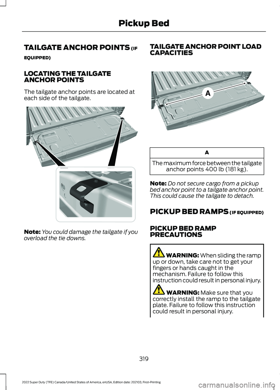
TAILGATE ANCHOR POINTS (IF
EQUIPPED)
LOCATING THE TAILGATE
ANCHOR POINTS
The tailgate anchor points are located at
each side of the tailgate. Note:
You could damage the tailgate if you
overload the tie downs. TAILGATE ANCHOR POINT LOAD
CAPACITIES A
The maximum force between the tailgate anchor points
400 lb (181 kg).
Note: Do not secure cargo from a pickup
bed anchor point to a tailgate anchor point.
This could cause the tailgate to detach.
PICKUP BED RAMPS (IF EQUIPPED)
PICKUP BED RAMP
PRECAUTIONS WARNING:
When sliding the ramp
up or down, take care not to get your
fingers or hands caught in the
mechanism. Failure to follow this
instruction could result in personal injury. WARNING:
Make sure that you
correctly install the ramp to the tailgate
plate. Failure to follow this instruction
could result in personal injury.
319
2022 Super Duty (TFE) Canada/United States of America, enUSA, Edition date: 202103, First-Printing Pickup BedE327594 E327790
Page 323 of 740
WARNING: Do not step or sit on
the ramp when it is in the stowed
position. Failure to follow this instruction
could result in personal injury. WARNING:
Only install the ramp
within the prescribed ramp angles.
Failure to follow this instruction could
result in personal injury.
Note: Each pickup bed ramp has a
maximum capacity of
400 lb (181.4 kg).
Note: Verify the ramp is on stable ground
before usage.
Note: For loading and unloading
equipment, your ramp should be set
between 10 degrees upward and 26 degrees
downward to avoid damage to the ramp
claw and tailgate plate.
Note: When using your vehicle for off-road
operation, remove the bed ramps from the
vehicle and store them in a safe location
away from your vehicle.
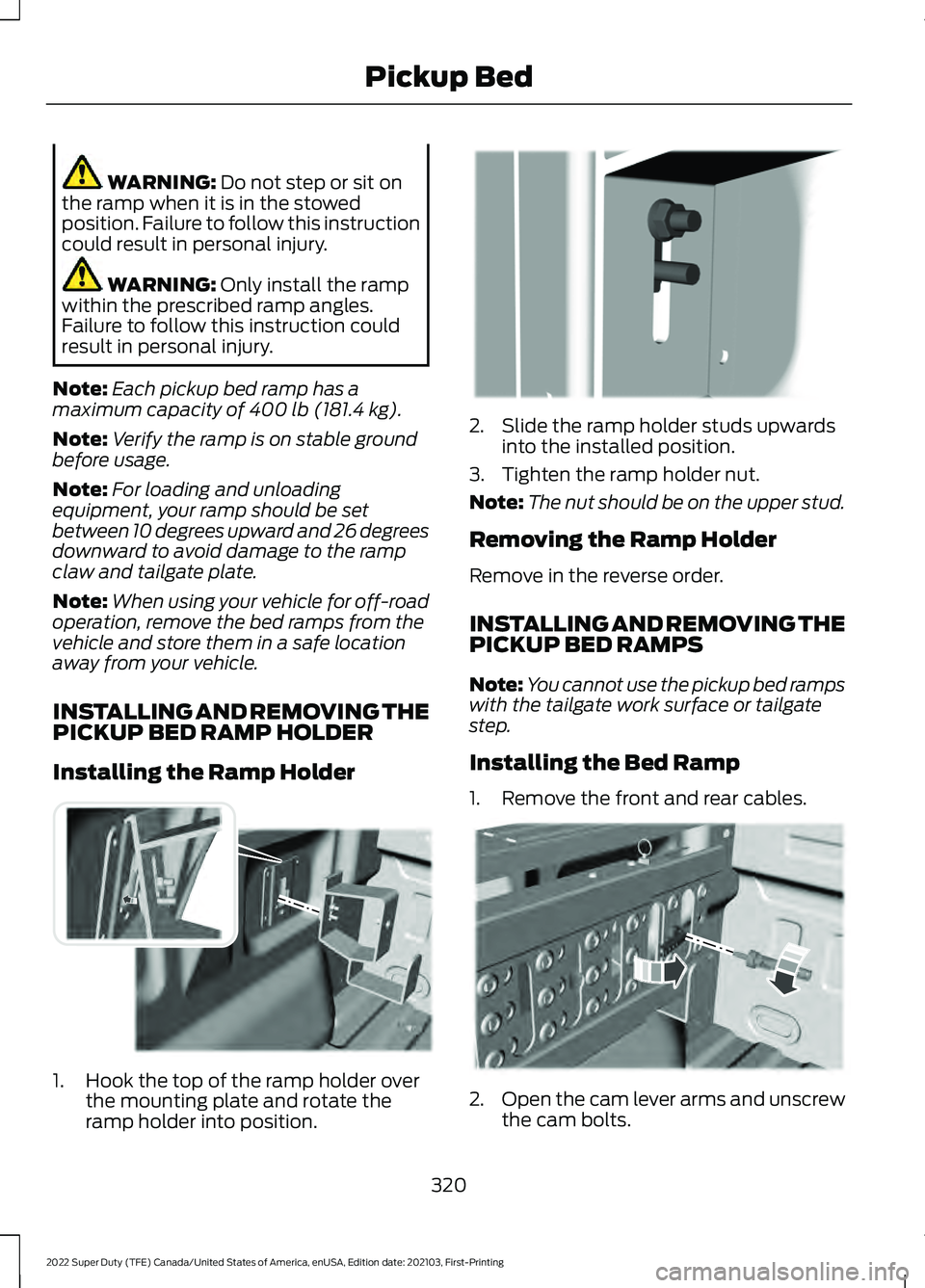
INSTALLING AND REMOVING THE
PICKUP BED RAMP HOLDER
Installing the Ramp Holder 1. Hook the top of the ramp holder over
the mounting plate and rotate the
ramp holder into position. 2. Slide the ramp holder studs upwards
into the installed position.
3. Tighten the ramp holder nut.
Note: The nut should be on the upper stud.
Removing the Ramp Holder
Remove in the reverse order.
INSTALLING AND REMOVING THE
PICKUP BED RAMPS
Note: You cannot use the pickup bed ramps
with the tailgate work surface or tailgate
step.
Installing the Bed Ramp
1. Remove the front and rear cables. 2.
Open the cam lever arms and unscrew
the cam bolts.
320
2022 Super Duty (TFE) Canada/United States of America, enUSA, Edition date: 202103, First-Printing Pickup BedE194387 E194388 E194380
Page 324 of 740
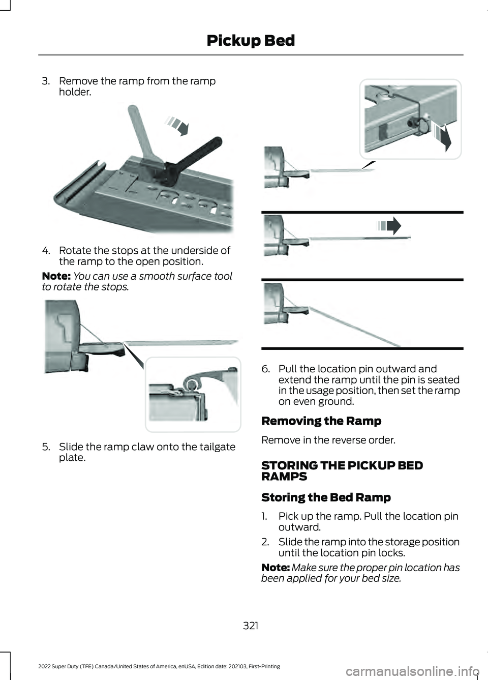
3. Remove the ramp from the ramp
holder. 4. Rotate the stops at the underside of
the ramp to the open position.
Note: You can use a smooth surface tool
to rotate the stops. 5. Slide the ramp claw onto the tailgate
plate. 6. Pull the location pin outward and
extend the ramp until the pin is seated
in the usage position, then set the ramp
on even ground.
Removing the Ramp
Remove in the reverse order.
STORING THE PICKUP BED
RAMPS
Storing the Bed Ramp
1. Pick up the ramp. Pull the location pin outward.
2. Slide the ramp into the storage position
until the location pin locks.
Note: Make sure the proper pin location has
been applied for your bed size.
321
2022 Super Duty (TFE) Canada/United States of America, enUSA, Edition date: 202103, First-Printing Pickup BedE211150 E194382 E194383
Page 325 of 740
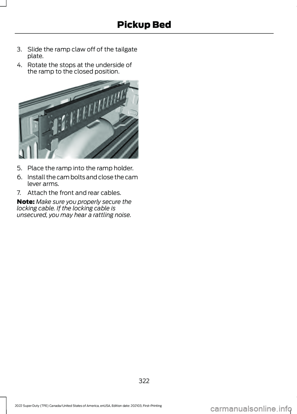
3. Slide the ramp claw off of the tailgate
plate.
4. Rotate the stops at the underside of the ramp to the closed position. 5. Place the ramp into the ramp holder.
6.
Install the cam bolts and close the cam
lever arms.
7. Attach the front and rear cables.
Note: Make sure you properly secure the
locking cable. If the locking cable is
unsecured, you may hear a rattling noise.
322
2022 Super Duty (TFE) Canada/United States of America, enUSA, Edition date: 202103, First-Printing Pickup BedE194391
Page 345 of 740
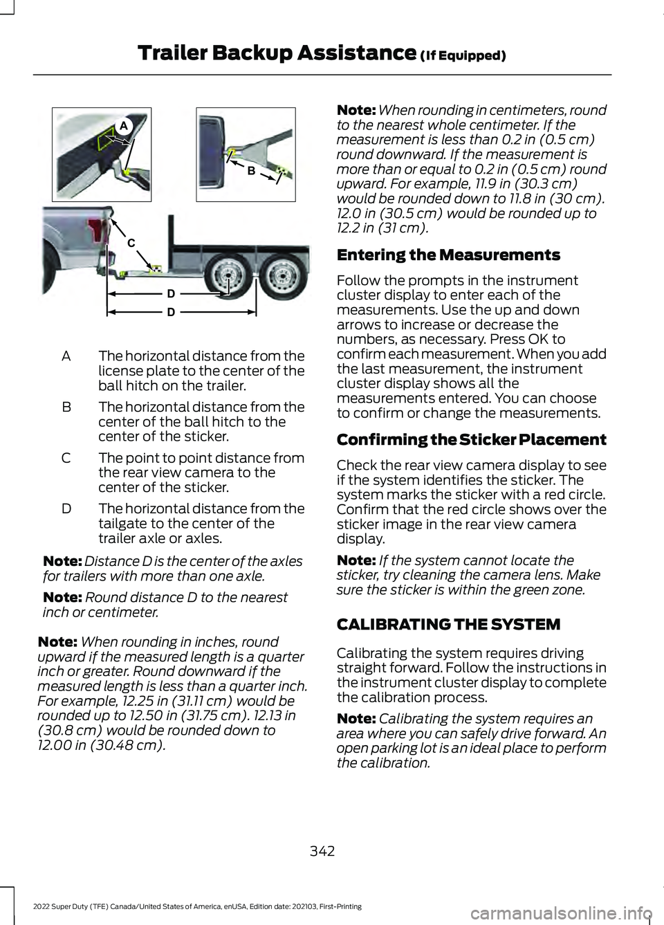
The horizontal distance from the
license plate to the center of the
ball hitch on the trailer.
A
The horizontal distance from the
center of the ball hitch to the
center of the sticker.
B
The point to point distance from
the rear view camera to the
center of the sticker.
C
The horizontal distance from the
tailgate to the center of the
trailer axle or axles.
D
Note: Distance D is the center of the axles
for trailers with more than one axle.
Note: Round distance D to the nearest
inch or centimeter.
Note: When rounding in inches, round
upward if the measured length is a quarter
inch or greater. Round downward if the
measured length is less than a quarter inch.
For example, 12.25 in (31.11 cm) would be
rounded up to 12.50 in (31.75 cm). 12.13 in
(30.8 cm) would be rounded down to
12.00 in (30.48 cm). Note:
When rounding in centimeters, round
to the nearest whole centimeter. If the
measurement is less than
0.2 in (0.5 cm)
round downward. If the measurement is
more than or equal to 0.2 in (0.5 cm) round
upward. For example, 11.9 in (30.3 cm)
would be rounded down to
11.8 in (30 cm).
12.0 in (30.5 cm) would be rounded up to
12.2 in (31 cm).
Entering the Measurements
Follow the prompts in the instrument
cluster display to enter each of the
measurements. Use the up and down
arrows to increase or decrease the
numbers, as necessary. Press OK to
confirm each measurement. When you add
the last measurement, the instrument
cluster display shows all the
measurements entered. You can choose
to confirm or change the measurements.
Confirming the Sticker Placement
Check the rear view camera display to see
if the system identifies the sticker. The
system marks the sticker with a red circle.
Confirm that the red circle shows over the
sticker image in the rear view camera
display.
Note: If the system cannot locate the
sticker, try cleaning the camera lens. Make
sure the sticker is within the green zone.
CALIBRATING THE SYSTEM
Calibrating the system requires driving
straight forward. Follow the instructions in
the instrument cluster display to complete
the calibration process.
Note: Calibrating the system requires an
area where you can safely drive forward. An
open parking lot is an ideal place to perform
the calibration.
342
2022 Super Duty (TFE) Canada/United States of America, enUSA, Edition date: 202103, First-Printing Trailer Backup Assistance
(If Equipped)A
B
C
D
DE209806