FORD F-600 2022 Owners Manual
Manufacturer: FORD, Model Year: 2022, Model line: F-600, Model: FORD F-600 2022Pages: 740, PDF Size: 12.6 MB
Page 361 of 740
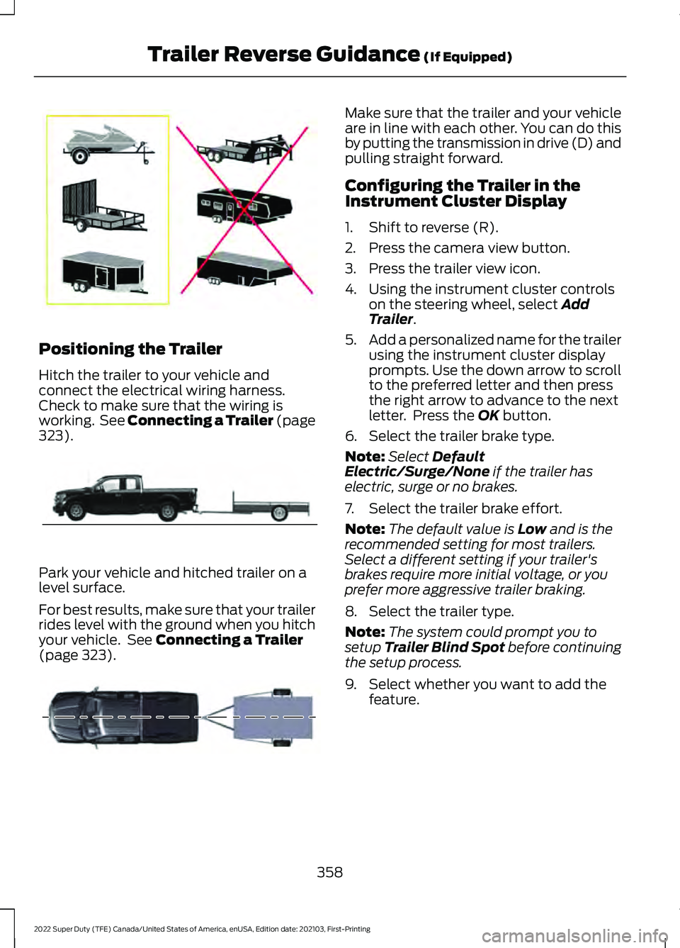
Positioning the Trailer
Hitch the trailer to your vehicle and
connect the electrical wiring harness.
Check to make sure that the wiring is
working. See Connecting a Trailer (page
323).
Park your vehicle and hitched trailer on a
level surface.
For best results, make sure that your trailer
rides level with the ground when you hitch
your vehicle. See
Connecting a Trailer
(page 323). Make sure that the trailer and your vehicle
are in line with each other. You can do this
by putting the transmission in drive (D) and
pulling straight forward.
Configuring the Trailer in the
Instrument Cluster Display
1. Shift to reverse (R).
2. Press the camera view button.
3. Press the trailer view icon.
4. Using the instrument cluster controls
on the steering wheel, select
Add
Trailer.
5. Add a personalized name for the trailer
using the instrument cluster display
prompts. Use the down arrow to scroll
to the preferred letter and then press
the right arrow to advance to the next
letter. Press the
OK button.
6. Select the trailer brake type.
Note: Select
Default
Electric/Surge/None if the trailer has
electric, surge or no brakes.
7. Select the trailer brake effort.
Note: The default value is
Low and is the
recommended setting for most trailers.
Select a different setting if your trailer's
brakes require more initial voltage, or you
prefer more aggressive trailer braking.
8. Select the trailer type.
Note: The system could prompt you to
setup
Trailer Blind Spot before continuing
the setup process.
9. Select whether you want to add the feature.
358
2022 Super Duty (TFE) Canada/United States of America, enUSA, Edition date: 202103, First-Printing Trailer Reverse Guidance
(If Equipped)E209766 E209759 E209760
Page 362 of 740
APPLYING THE TRAILER
REVERSE AID STICKER
Placing the Sticker
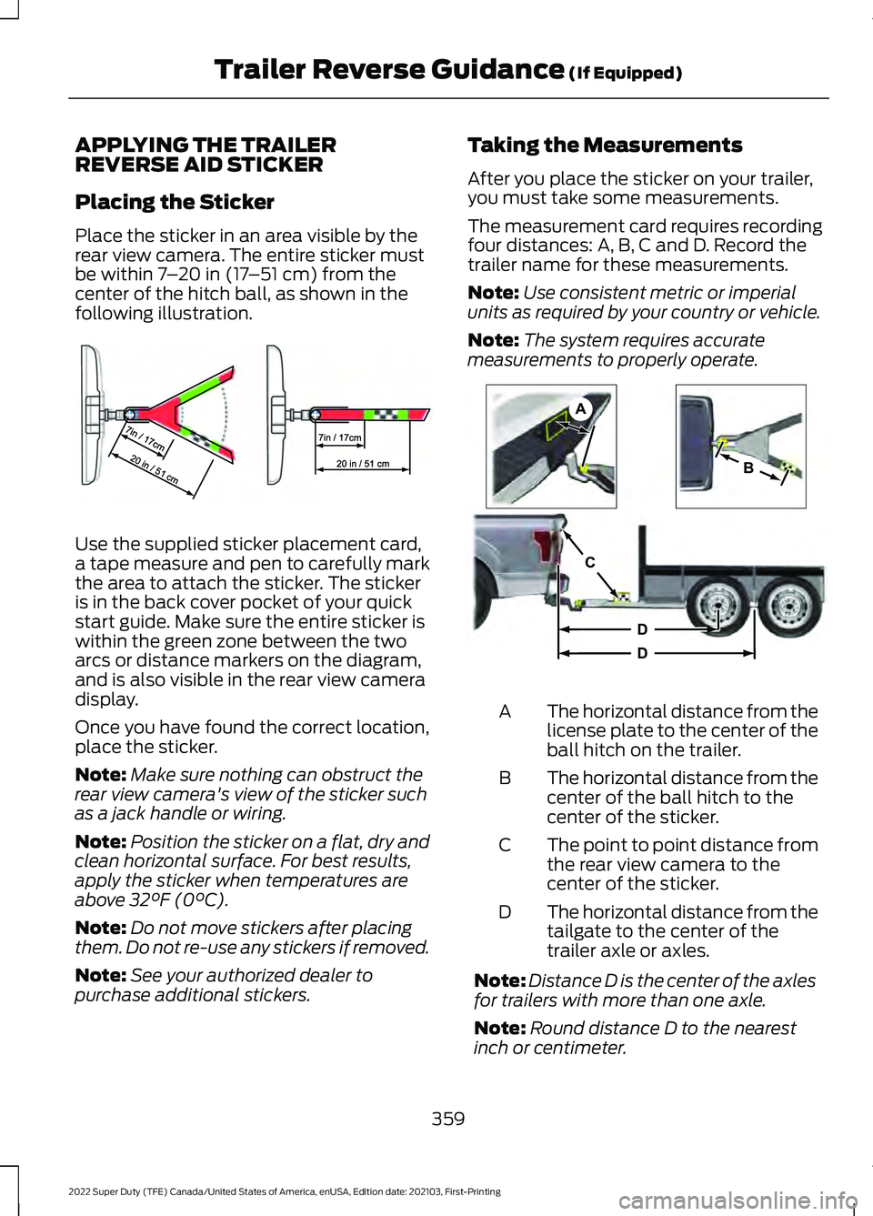
Place the sticker in an area visible by the
rear view camera. The entire sticker must
be within 7
– 20 in (17 –51 cm) from the
center of the hitch ball, as shown in the
following illustration. Use the supplied sticker placement card,
a tape measure and pen to carefully mark
the area to attach the sticker. The sticker
is in the back cover pocket of your quick
start guide. Make sure the entire sticker is
within the green zone between the two
arcs or distance markers on the diagram,
and is also visible in the rear view camera
display.
Once you have found the correct location,
place the sticker.
Note:
Make sure nothing can obstruct the
rear view camera's view of the sticker such
as a jack handle or wiring.
Note: Position the sticker on a flat, dry and
clean horizontal surface. For best results,
apply the sticker when temperatures are
above
32°F (0°C).
Note: Do not move stickers after placing
them. Do not re-use any stickers if removed.
Note: See your authorized dealer to
purchase additional stickers. Taking the Measurements
After you place the sticker on your trailer,
you must take some measurements.
The measurement card requires recording
four distances: A, B, C and D. Record the
trailer name for these measurements.
Note:
Use consistent metric or imperial
units as required by your country or vehicle.
Note: The system requires accurate
measurements to properly operate. The horizontal distance from the
license plate to the center of the
ball hitch on the trailer.
A
The horizontal distance from the
center of the ball hitch to the
center of the sticker.
B
The point to point distance from
the rear view camera to the
center of the sticker.
C
The horizontal distance from the
tailgate to the center of the
trailer axle or axles.
D
Note: Distance D is the center of the axles
for trailers with more than one axle.
Note: Round distance D to the nearest
inch or centimeter.
359
2022 Super Duty (TFE) Canada/United States of America, enUSA, Edition date: 202103, First-Printing Trailer Reverse Guidance
(If Equipped)E310619 A
B
C
D
DE209806
Page 363 of 740
Note:
When rounding in inches, round
upward if the measured length is a quarter
inch or greater. Round downward if the
measured length is less than a quarter inch.
For example, 12.25 in (31.11 cm) would be
rounded up to 12.50 in (31.75 cm). 12.13 in
(30.8 cm) would be rounded down to
12.00 in (30.48 cm).
Note: When rounding in centimeters, round
to the nearest whole centimeter. If the
measurement is less than
0.2 in (0.5 cm)
round downward. If the measurement is
more than or equal to 0.2 in (0.5 cm) round
upward. For example, 11.9 in (30.3 cm)
would be rounded down to
11.8 in (30 cm).
12.0 in (30.5 cm) would be rounded up to
12.2 in (31 cm).
Entering the Measurements
Follow the prompts in the instrument
cluster display to enter each of the
measurements. Use the up and down
arrows to increase or decrease the
numbers, as necessary. Press OK to
confirm each measurement. When you add
the last measurement, the instrument
cluster display shows all the
measurements entered. You can choose
to confirm or change the measurements.
Confirming the Sticker Placement
Check the rear view camera display to see
if the system identifies the sticker. The
system marks the sticker with a red circle.
Confirm that the red circle shows over the
sticker image in the rear view camera
display.
Note: If the system cannot locate the
sticker, try cleaning the camera lens. Make
sure the sticker is within the green zone. CALIBRATING THE SYSTEM
Calibrating the system requires driving
straight forward. Follow the instructions in
the instrument cluster display to complete
the calibration process.
Note:
Calibrating the system requires an
area where you can safely drive forward. An
open parking lot is an ideal place to perform
the calibration.
Note: Keep the steering wheel straight
when instructed to by the instrument cluster
display. If the steering wheel is in a turned
position during this instruction, the
calibration pauses.
Note: The system is designed to work with
drawbars that have a license plate to hitch
ball center measurement of
9– 20 in
(23–52 cm) when installed. Do not attempt
to use drawbars or trailers that have a
length outside of this range as the system
performance degrades and could cause
improper system function.
Note: The instrument cluster display shows
if you are going too slow or fast. Calibration
pauses if the speed is outside the required
range of
4– 24 mph (6– 39 km/h).
Note: For best results, do not calibrate the
system at night when calibrating the system
with the sticker.
SETTING UP TRAILER
REVERSE GUIDANCE FOR A
FIFTH-WHEEL OR GOOSENECK
TRAILER
CONFIGURING THE TRAILER
You must configure a trailer in the system
to use trailer reverse guidance. This is a
one-time setup process and the trailer
information is saved in the system for the
next time you use that trailer.
360
2022 Super Duty (TFE) Canada/United States of America, enUSA, Edition date: 202103, First-Printing Trailer Reverse Guidance
(If Equipped)
Page 364 of 740
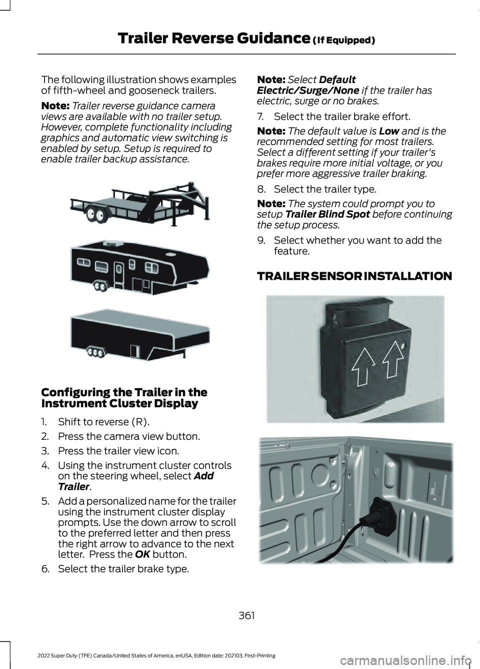
The following illustration shows examples
of fifth-wheel and gooseneck trailers.
Note:
Trailer reverse guidance camera
views are available with no trailer setup.
However, complete functionality including
graphics and automatic view switching is
enabled by setup. Setup is required to
enable trailer backup assistance. Configuring the Trailer in the
Instrument Cluster Display
1. Shift to reverse (R).
2. Press the camera view button.
3. Press the trailer view icon.
4. Using the instrument cluster controls
on the steering wheel, select Add
Trailer.
5. Add a personalized name for the trailer
using the instrument cluster display
prompts. Use the down arrow to scroll
to the preferred letter and then press
the right arrow to advance to the next
letter. Press the
OK button.
6. Select the trailer brake type. Note:
Select
Default
Electric/Surge/None if the trailer has
electric, surge or no brakes.
7. Select the trailer brake effort.
Note: The default value is
Low and is the
recommended setting for most trailers.
Select a different setting if your trailer's
brakes require more initial voltage, or you
prefer more aggressive trailer braking.
8. Select the trailer type.
Note: The system could prompt you to
setup
Trailer Blind Spot before continuing
the setup process.
9. Select whether you want to add the feature.
TRAILER SENSOR INSTALLATION 361
2022 Super Duty (TFE) Canada/United States of America, enUSA, Edition date: 202103, First-Printing Trailer Reverse Guidance
(If Equipped)E311877 E315959 E316145
Page 365 of 740
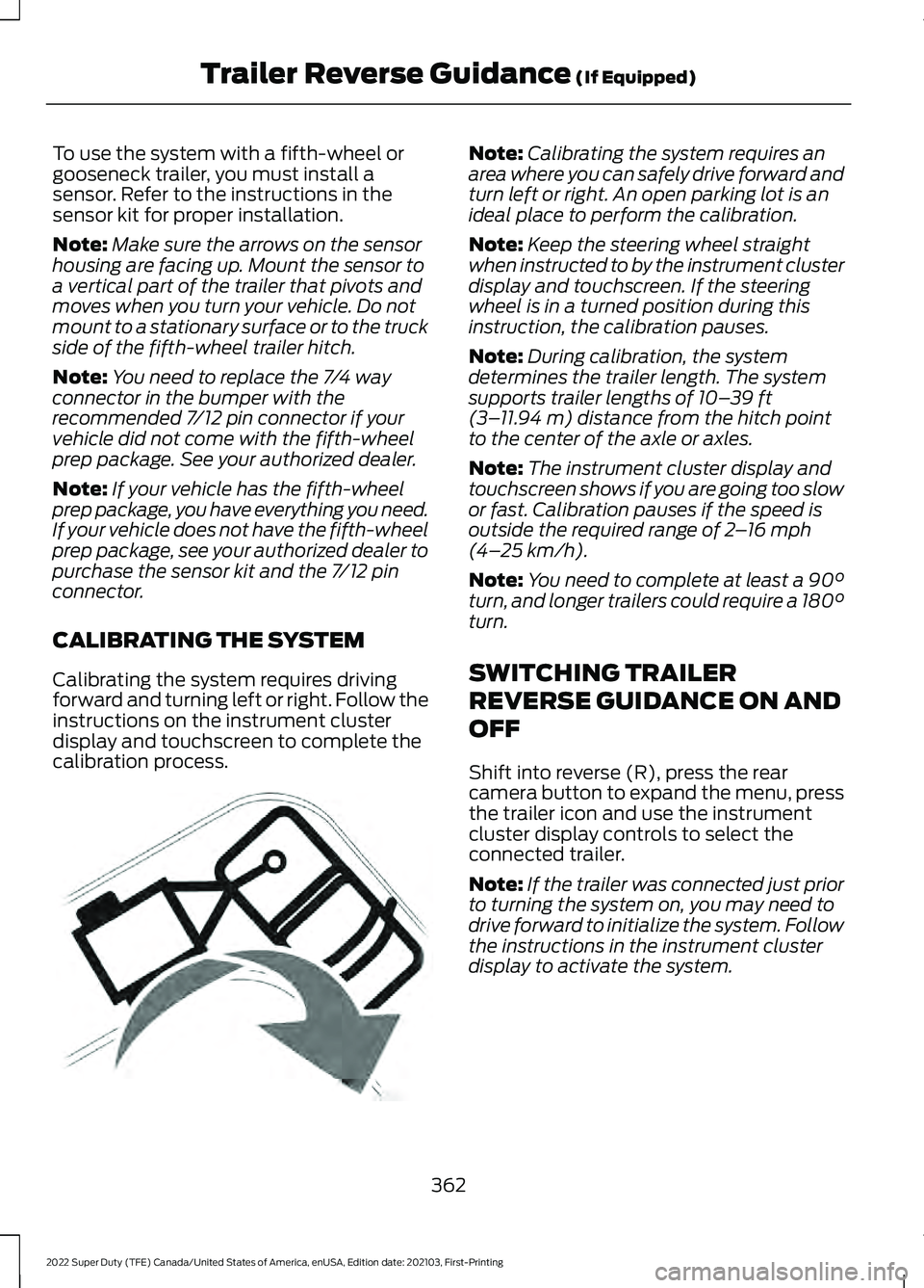
To use the system with a fifth-wheel or
gooseneck trailer, you must install a
sensor. Refer to the instructions in the
sensor kit for proper installation.
Note:
Make sure the arrows on the sensor
housing are facing up. Mount the sensor to
a vertical part of the trailer that pivots and
moves when you turn your vehicle. Do not
mount to a stationary surface or to the truck
side of the fifth-wheel trailer hitch.
Note: You need to replace the 7/4 way
connector in the bumper with the
recommended 7/12 pin connector if your
vehicle did not come with the fifth-wheel
prep package. See your authorized dealer.
Note: If your vehicle has the fifth-wheel
prep package, you have everything you need.
If your vehicle does not have the fifth-wheel
prep package, see your authorized dealer to
purchase the sensor kit and the 7/12 pin
connector.
CALIBRATING THE SYSTEM
Calibrating the system requires driving
forward and turning left or right. Follow the
instructions on the instrument cluster
display and touchscreen to complete the
calibration process. Note:
Calibrating the system requires an
area where you can safely drive forward and
turn left or right. An open parking lot is an
ideal place to perform the calibration.
Note: Keep the steering wheel straight
when instructed to by the instrument cluster
display and touchscreen. If the steering
wheel is in a turned position during this
instruction, the calibration pauses.
Note: During calibration, the system
determines the trailer length. The system
supports trailer lengths of 10– 39 ft
(3– 11.94 m) distance from the hitch point
to the center of the axle or axles.
Note: The instrument cluster display and
touchscreen shows if you are going too slow
or fast. Calibration pauses if the speed is
outside the required range of
2 – 16 mph
(4– 25 km/h).
Note: You need to complete at least a 90°
turn, and longer trailers could require a 180°
turn.
SWITCHING TRAILER
REVERSE GUIDANCE ON AND
OFF
Shift into reverse (R), press the rear
camera button to expand the menu, press
the trailer icon and use the instrument
cluster display controls to select the
connected trailer.
Note: If the trailer was connected just prior
to turning the system on, you may need to
drive forward to initialize the system. Follow
the instructions in the instrument cluster
display to activate the system.
362
2022 Super Duty (TFE) Canada/United States of America, enUSA, Edition date: 202103, First-Printing Trailer Reverse Guidance
(If Equipped)E346605
Page 366 of 740
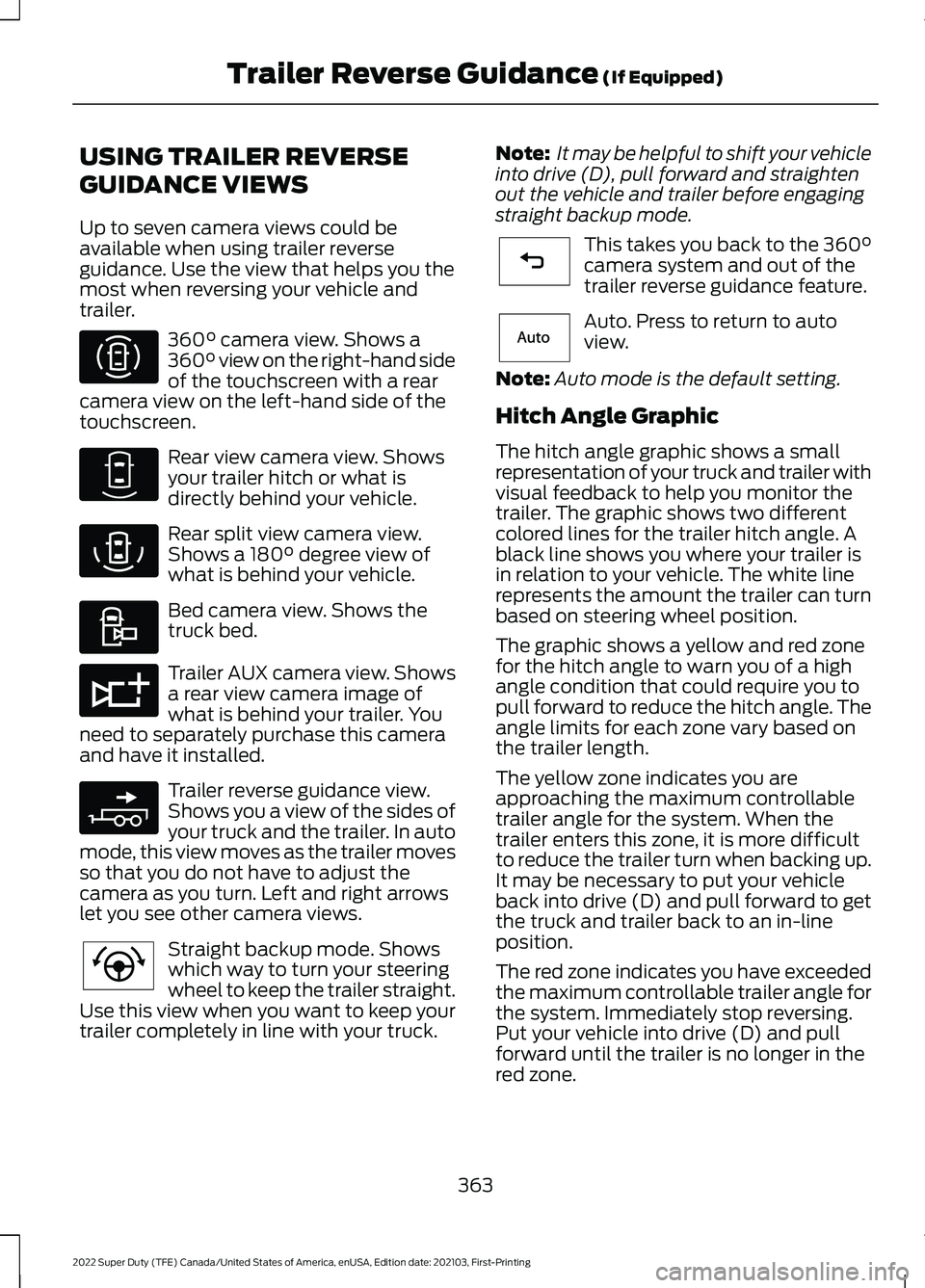
USING TRAILER REVERSE
GUIDANCE VIEWS
Up to seven camera views could be
available when using trailer reverse
guidance. Use the view that helps you the
most when reversing your vehicle and
trailer.
360° camera view. Shows a
360° view on the right-hand side
of the touchscreen with a rear
camera view on the left-hand side of the
touchscreen. Rear view camera view. Shows
your trailer hitch or what is
directly behind your vehicle.
Rear split view camera view.
Shows a
180° degree view of
what is behind your vehicle. Bed camera view. Shows the
truck bed.
Trailer AUX camera view. Shows
a rear view camera image of
what is behind your trailer. You
need to separately purchase this camera
and have it installed. Trailer reverse guidance view.
Shows you a view of the sides of
your truck and the trailer. In auto
mode, this view moves as the trailer moves
so that you do not have to adjust the
camera as you turn. Left and right arrows
let you see other camera views. Straight backup mode. Shows
which way to turn your steering
wheel to keep the trailer straight.
Use this view when you want to keep your
trailer completely in line with your truck. Note:
It may be helpful to shift your vehicle
into drive (D), pull forward and straighten
out the vehicle and trailer before engaging
straight backup mode. This takes you back to the
360°
camera system and out of the
trailer reverse guidance feature. Auto. Press to return to auto
view.
Note: Auto mode is the default setting.
Hitch Angle Graphic
The hitch angle graphic shows a small
representation of your truck and trailer with
visual feedback to help you monitor the
trailer. The graphic shows two different
colored lines for the trailer hitch angle. A
black line shows you where your trailer is
in relation to your vehicle. The white line
represents the amount the trailer can turn
based on steering wheel position.
The graphic shows a yellow and red zone
for the hitch angle to warn you of a high
angle condition that could require you to
pull forward to reduce the hitch angle. The
angle limits for each zone vary based on
the trailer length.
The yellow zone indicates you are
approaching the maximum controllable
trailer angle for the system. When the
trailer enters this zone, it is more difficult
to reduce the trailer turn when backing up.
It may be necessary to put your vehicle
back into drive (D) and pull forward to get
the truck and trailer back to an in-line
position.
The red zone indicates you have exceeded
the maximum controllable trailer angle for
the system. Immediately stop reversing.
Put your vehicle into drive (D) and pull
forward until the trailer is no longer in the
red zone.
363
2022 Super Duty (TFE) Canada/United States of America, enUSA, Edition date: 202103, First-Printing Trailer Reverse Guidance
(If Equipped)E310996 E310967 E310974 E310995 E311776 E310965 E224484 E224486 E315644
Page 367 of 740
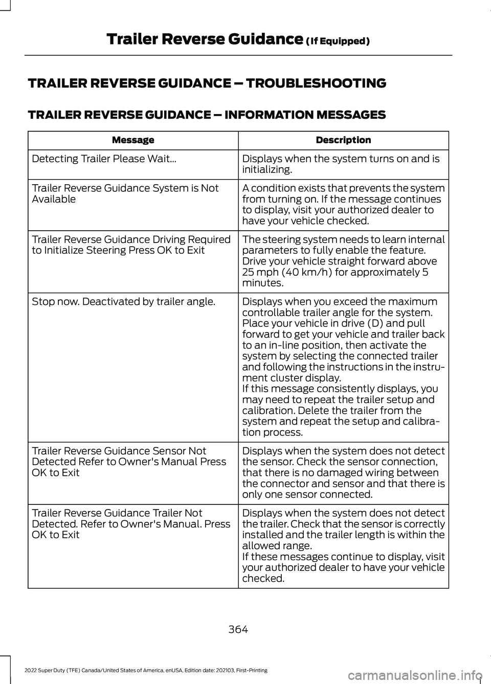
TRAILER REVERSE GUIDANCE – TROUBLESHOOTING
TRAILER REVERSE GUIDANCE – INFORMATION MESSAGES
Description
Message
Displays when the system turns on and is
initializing.
Detecting Trailer Please Wait…
A condition exists that prevents the system
from turning on. If the message continues
to display, visit your authorized dealer to
have your vehicle checked.
Trailer Reverse Guidance System is Not
Available
The steering system needs to learn internal
parameters to fully enable the feature.
Drive your vehicle straight forward above
25 mph (40 km/h) for approximately 5
minutes.
Trailer Reverse Guidance Driving Required
to Initialize Steering Press OK to Exit
Displays when you exceed the maximum
controllable trailer angle for the system.
Place your vehicle in drive (D) and pull
forward to get your vehicle and trailer back
to an in-line position, then activate the
system by selecting the connected trailer
and following the instructions in the instru-
ment cluster display.
Stop now. Deactivated by trailer angle.
If this message consistently displays, you
may need to repeat the trailer setup and
calibration. Delete the trailer from the
system and repeat the setup and calibra-
tion process.
Displays when the system does not detect
the sensor. Check the sensor connection,
that there is no damaged wiring between
the connector and sensor and that there is
only one sensor connected.
Trailer Reverse Guidance Sensor Not
Detected Refer to Owner's Manual Press
OK to Exit
Displays when the system does not detect
the trailer. Check that the sensor is correctly
installed and the trailer length is within the
allowed range.
Trailer Reverse Guidance Trailer Not
Detected. Refer to Owner's Manual. Press
OK to Exit
If these messages continue to display, visit
your authorized dealer to have your vehicle
checked.
364
2022 Super Duty (TFE) Canada/United States of America, enUSA, Edition date: 202103, First-Printing Trailer Reverse Guidance
(If Equipped)
Page 368 of 740
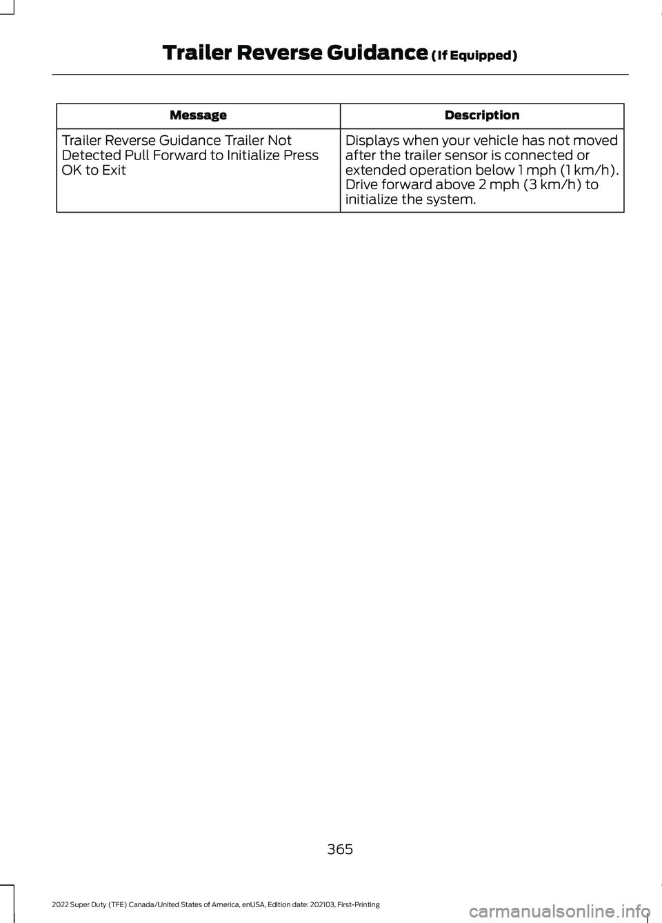
Description
Message
Displays when your vehicle has not moved
after the trailer sensor is connected or
extended operation below 1 mph (1 km/h).
Drive forward above 2 mph (3 km/h) to
initialize the system.
Trailer Reverse Guidance Trailer Not
Detected Pull Forward to Initialize Press
OK to Exit
365
2022 Super Duty (TFE) Canada/United States of America, enUSA, Edition date: 202103, First-Printing Trailer Reverse Guidance
(If Equipped)
Page 369 of 740
TRAILER REVERSE GUIDANCE –
FREQUENTLY ASKED QUESTIONS
What does it mean if Measurement A
has reached maximum or minimum
value?
The system is designed to work with
drawbars that have a license plate to
hitch ball center measurement of
9–20 in (23–52 cm) when installed.
Do not attempt to use drawbars that
have a length outside this range as the
system performance degrades and
could cause improper system function.
Make sure that the measurement
being made is the horizontal distance
only from the license plate to the hitch
ball center. A straight line distance
that includes any vertical rise or drop
increases the measurement and
makes it inaccurate. Inaccurate
measurements degrade system
performance and could cause
improper system function. See
Applying the Trailer Reverse Aid
Sticker
(page 359).
What does it mean if Measurement B
has reached its maximum or minimum
value? Make sure that the sticker is properly
placed. Stickers placed outside the
allowed zone adversely affects the
system performance and could cause
improper feature function. Make sure
that the measurement being made is
the horizontal distance only from
center of the sticker to the hitch ball
center. A straight line distance that
includes any vertical rise or drop
increases the measurement and
causes an inaccurate value to be
entered into the system. See
Applying the Trailer Reverse Aid
Sticker
(page 359). What does it mean if Measurement C
has reached its maximum or minimum
value?
Make sure you follow the sticker
placement instructions. Stickers
placed outside the allowed zone
adversely affect the system
performance and could cause
improper feature function. If you have
met all the criteria for sticker
placement and you see this message,
the sticker is either too far below or too
close to the camera to properly
recognize the sticker. For the system
to correctly operate, lower the sticker
height if you receive the minimum
warning or raise the sticker height if
you receive the maximum warning.
Only one sticker can be placed on the
trailer for correct system function. The
previous sticker must be removed or
covered so only one sticker is visible
to the camera. Measurement B and C
must be measured again if a new
sticker is placed on the trailer. See
Applying the Trailer Reverse Aid
Sticker
(page 359).
What does it mean if Measurement D
has reached its maximum or minimum
value? Make sure that the measurement
being made is the horizontal distance
only from tailgate to the center of the
single axle or the center of all the axles
on the trailer. The system does not
support trailer lengths outside the
range allowed by the information
display. See
Applying the Trailer
Reverse Aid Sticker (page 359).
366
2022 Super Duty (TFE) Canada/United States of America, enUSA, Edition date: 202103, First-Printing Trailer Reverse Guidance
(If Equipped)
Page 370 of 740
Why does the trailer not reverse
straight when using a conventional
trailer?
Factors such as the drawbar
connection to the hitch receiver, road
camber, road grade and compliance
in the trailer suspension can influence
how straight the system is able to
reverse your trailer when the knob is
not turned. You can compensate for
the trailer drifting to the right or left by
slowly turning the knob until the trailer
is following your preferred path and
then holding the knob in that position.
If you would like to recalibrate the
system for straight backing, change
the sticker option in the instrument
cluster display. Confirm the
measurements, and the system
prompts you to perform the calibration
procedure.
Why does the trailer not reverse
straight when using a fifth-wheel or
gooseneck trailer? Verify the sensor is correctly installed.
Other factors such as the hitch
connection, road camber, road slope
and trailer suspension could influence
how straight the system can reverse
the trailer when the control knob is not
turned. You can compensate for the
trailer drifting to the right or left by
slowly turning the knob until the trailer
is following your desired path and then
holding the knob in that position. Why does the system not detect a
sensor?
There could be an issue with the
connection, the wiring harness could
be damaged, you could have multiple
sensors connected or the sensor could
be incorrectly installed. Check that the
12-way connector is fully inserted into
the 12-way socket. The red rubber seal
is not visible when the connector is
fully inserted. Also check that the
wiring harness sensor connection is
fully inserted at the trailer sensor, and
check for damaged wiring between
the 12-way connector and the trailer
sensor. Also, check that the sensor is
installed on a vertical surface with the
arrows pointing straight up.
What does it mean if the system
remains on one message for an
extended time during calibration when
setting up the system with a
conventional trailer? The camera could need to be cleaned,
the sticker could be blocked, the
drawbar could be outside the allowed
range of 4–19 in (10–48 cm) or you
could need to move to a different area
to change the lighting and background.
Verify the sticker is in the proper
location. See
Applying the Trailer
Reverse Aid Sticker (page 359). You
can move to a different area or change
the direction you are driving or setup
the system at a different time of day.
Some trailers are not compatible with
the sticker and camera system.
What does it mean if the system pauses
during calibration? There could be steering input or trailer
movement during the straight drive
portion of the calibration process.
367
2022 Super Duty (TFE) Canada/United States of America, enUSA, Edition date: 202103, First-Printing Trailer Reverse Guidance
(If Equipped)