sensor FORD F-650/750 2022 Owner's Manual
[x] Cancel search | Manufacturer: FORD, Model Year: 2022, Model line: F-650/750, Model: FORD F-650/750 2022Pages: 379, PDF Size: 5.29 MB
Page 172 of 379
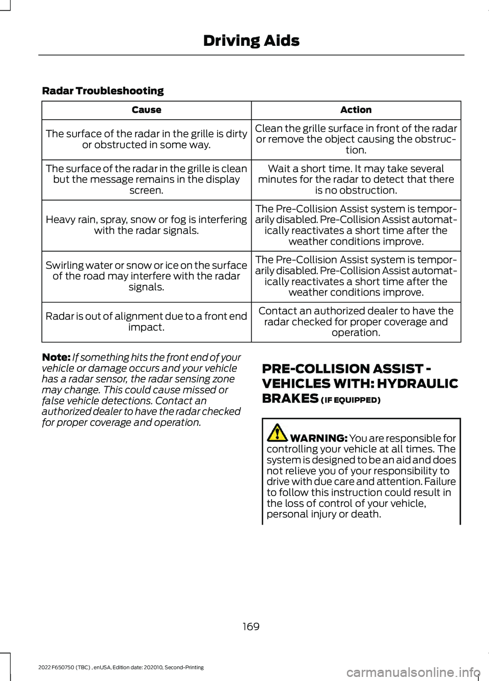
Radar Troubleshooting
Action
Cause
Clean the grille surface in front of the radaror remove the object causing the obstruc- tion.
The surface of the radar in the grille is dirty
or obstructed in some way.
Wait a short time. It may take several
minutes for the radar to detect that there is no obstruction.
The surface of the radar in the grille is clean
but the message remains in the display screen.
The Pre-Collision Assist system is tempor-
arily disabled. Pre-Collision Assist automat-ically reactivates a short time after the weather conditions improve.
Heavy rain, spray, snow or fog is interfering
with the radar signals.
The Pre-Collision Assist system is tempor-
arily disabled. Pre-Collision Assist automat-ically reactivates a short time after the weather conditions improve.
Swirling water or snow or ice on the surface
of the road may interfere with the radar signals.
Contact an authorized dealer to have theradar checked for proper coverage and operation.
Radar is out of alignment due to a front end
impact.
Note: If something hits the front end of your
vehicle or damage occurs and your vehicle
has a radar sensor, the radar sensing zone
may change. This could cause missed or
false vehicle detections. Contact an
authorized dealer to have the radar checked
for proper coverage and operation. PRE-COLLISION ASSIST -
VEHICLES WITH: HYDRAULIC
BRAKES (IF EQUIPPED) WARNING: You are responsible for
controlling your vehicle at all times. The
system is designed to be an aid and does
not relieve you of your responsibility to
drive with due care and attention. Failure
to follow this instruction could result in
the loss of control of your vehicle,
personal injury or death.
169
2022 F650750 (TBC) , enUSA, Edition date: 202010, Second-Printing Driving Aids
Page 175 of 379
Note:
We recommend that you switch the
system off if you install a snow plow or
similar object in such a way that it may
block the radar sensor. Your vehicle
remembers the selected setting across key
cycles.
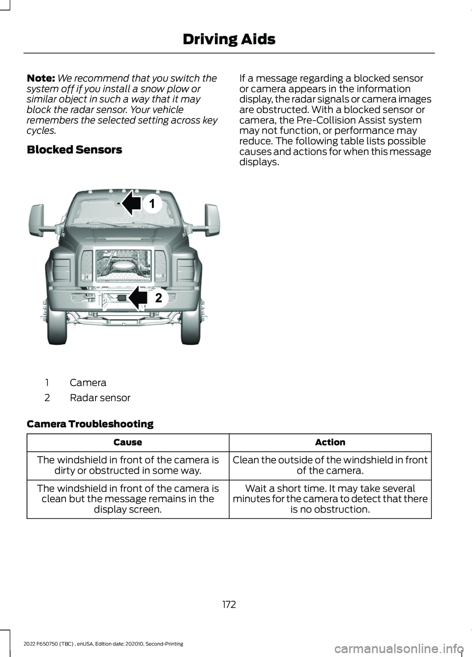
Blocked Sensors Camera
1
Radar sensor
2 If a message regarding a blocked sensor
or camera appears in the information
display, the radar signals or camera images
are obstructed. With a blocked sensor or
camera, the Pre-Collision Assist system
may not function, or performance may
reduce. The following table lists possible
causes and actions for when this message
displays.
Camera Troubleshooting Action
Cause
Clean the outside of the windshield in frontof the camera.
The windshield in front of the camera is
dirty or obstructed in some way.
Wait a short time. It may take several
minutes for the camera to detect that there is no obstruction.
The windshield in front of the camera is
clean but the message remains in the display screen.
172
2022 F650750 (TBC) , enUSA, Edition date: 202010, Second-Printing Driving AidsE311873
Page 176 of 379
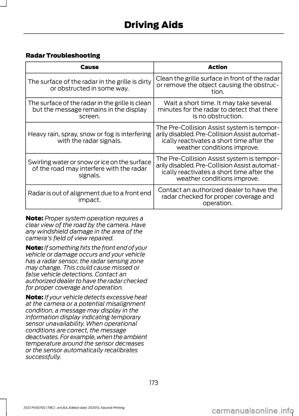
Radar Troubleshooting
Action
Cause
Clean the grille surface in front of the radaror remove the object causing the obstruc- tion.
The surface of the radar in the grille is dirty
or obstructed in some way.
Wait a short time. It may take several
minutes for the radar to detect that there is no obstruction.
The surface of the radar in the grille is clean
but the message remains in the display screen.
The Pre-Collision Assist system is tempor-
arily disabled. Pre-Collision Assist automat-ically reactivates a short time after the weather conditions improve.
Heavy rain, spray, snow or fog is interfering
with the radar signals.
The Pre-Collision Assist system is tempor-
arily disabled. Pre-Collision Assist automat-ically reactivates a short time after the weather conditions improve.
Swirling water or snow or ice on the surface
of the road may interfere with the radar signals.
Contact an authorized dealer to have theradar checked for proper coverage and operation.
Radar is out of alignment due to a front end
impact.
Note: Proper system operation requires a
clear view of the road by the camera. Have
any windshield damage in the area of the
camera's field of view repaired.
Note: If something hits the front end of your
vehicle or damage occurs and your vehicle
has a radar sensor, the radar sensing zone
may change. This could cause missed or
false vehicle detections. Contact an
authorized dealer to have the radar checked
for proper coverage and operation.
Note: If your vehicle detects excessive heat
at the camera or a potential misalignment
condition, a message may display in the
information display indicating temporary
sensor unavailability. When operational
conditions are correct, the message
deactivates. For example, when the ambient
temperature around the sensor decreases
or the sensor automatically recalibrates
successfully.
173
2022 F650750 (TBC) , enUSA, Edition date: 202010, Second-Printing Driving Aids
Page 204 of 379

Protected Component
Rating
Item
Body control module run
power 1 bus.
50 A
25
Not used.
—
26
Body builder battery feed.
20 A
27
Not used.
—
28
Alternator 1 A-Line.
10 A
29
Not used.
—
30
Hydromax pump.
60 A
31
Powertrain control module.
20 A
32
Canister vent solenoid (gas).
20 A
33
Canister purge solenoid
(gas).
Variable cam timing actu-
ator 11 (gas).
Heated exhaust gas oxygen
sensor (gas).
Urea tank power (diesel).
Exhaust gas recirculation
cool bypass valve (diesel).
A/C clutch relay.
10 A
34
Customer access vehicle
power 3 feed.
Variable oil pump (diesel).
Cooling fan (diesel).
Fan clutch (gas).
Exhaust brake switch.
Coil on plug (gas)
20 A
35
Urea tank (diesel).
Glow plug controller
(diesel).
Nitrogen oxide sensor
control module (diesel).
Particulate matter sensor
(diesel).
Fuel volume control value
(diesel).
10 A
36
Fuel pressure regulator
(diesel).
201
2022 F650750 (TBC) , enUSA, Edition date: 202010, Second-Printing Fuses
Page 209 of 379
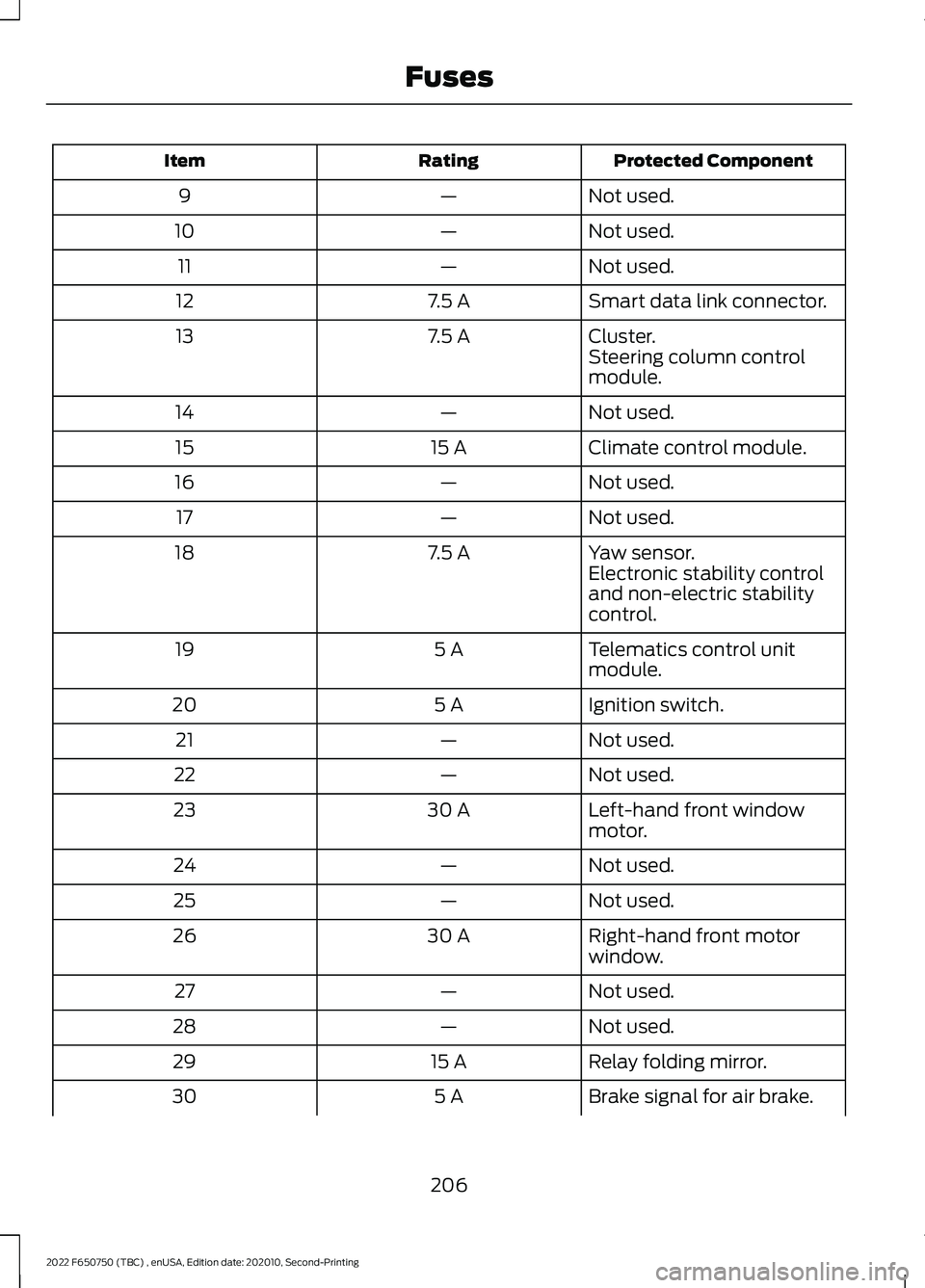
Protected Component
Rating
Item
Not used.
—
9
Not used.
—
10
Not used.
—
11
Smart data link connector.
7.5 A
12
Cluster.
7.5 A
13
Steering column control
module.
Not used.
—
14
Climate control module.
15 A
15
Not used.
—
16
Not used.
—
17
Yaw sensor.
7.5 A
18
Electronic stability control
and non-electric stability
control.
Telematics control unit
module.
5 A
19
Ignition switch.
5 A
20
Not used.
—
21
Not used.
—
22
Left-hand front window
motor.
30 A
23
Not used.
—
24
Not used.
—
25
Right-hand front motor
window.
30 A
26
Not used.
—
27
Not used.
—
28
Relay folding mirror.
15 A
29
Brake signal for air brake.
5 A
30
206
2022 F650750 (TBC) , enUSA, Edition date: 202010, Second-Printing Fuses
Page 231 of 379
Air Filter Replacement
When replacing the air filter element, use
a Motorcraft® air filter element. See
Motorcraft Parts (page 288).
Note: Failure to use the correct air filter
element may result in severe engine
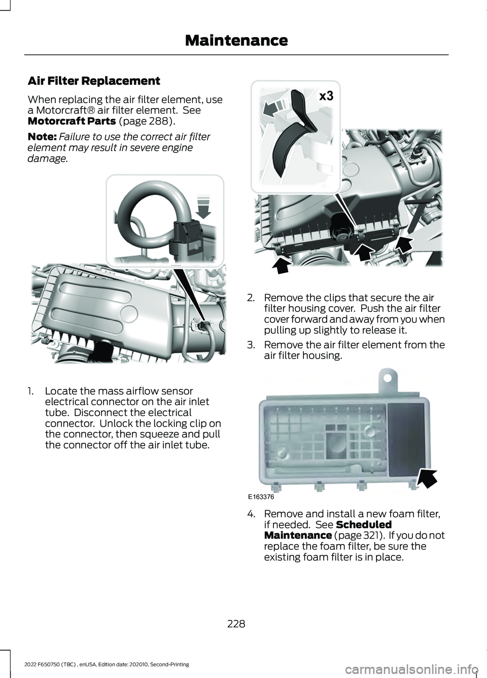
damage. 1. Locate the mass airflow sensor
electrical connector on the air inlet
tube. Disconnect the electrical
connector. Unlock the locking clip on
the connector, then squeeze and pull
the connector off the air inlet tube. 2. Remove the clips that secure the air
filter housing cover. Push the air filter
cover forward and away from you when
pulling up slightly to release it.
3. Remove the air filter element from the
air filter housing. 4. Remove and install a new foam filter,
if needed. See
Scheduled
Maintenance (page 321). If you do not
replace the foam filter, be sure the
existing foam filter is in place.
228
2022 F650750 (TBC) , enUSA, Edition date: 202010, Second-Printing MaintenanceE317651 x3E317652 E163376
Page 232 of 379
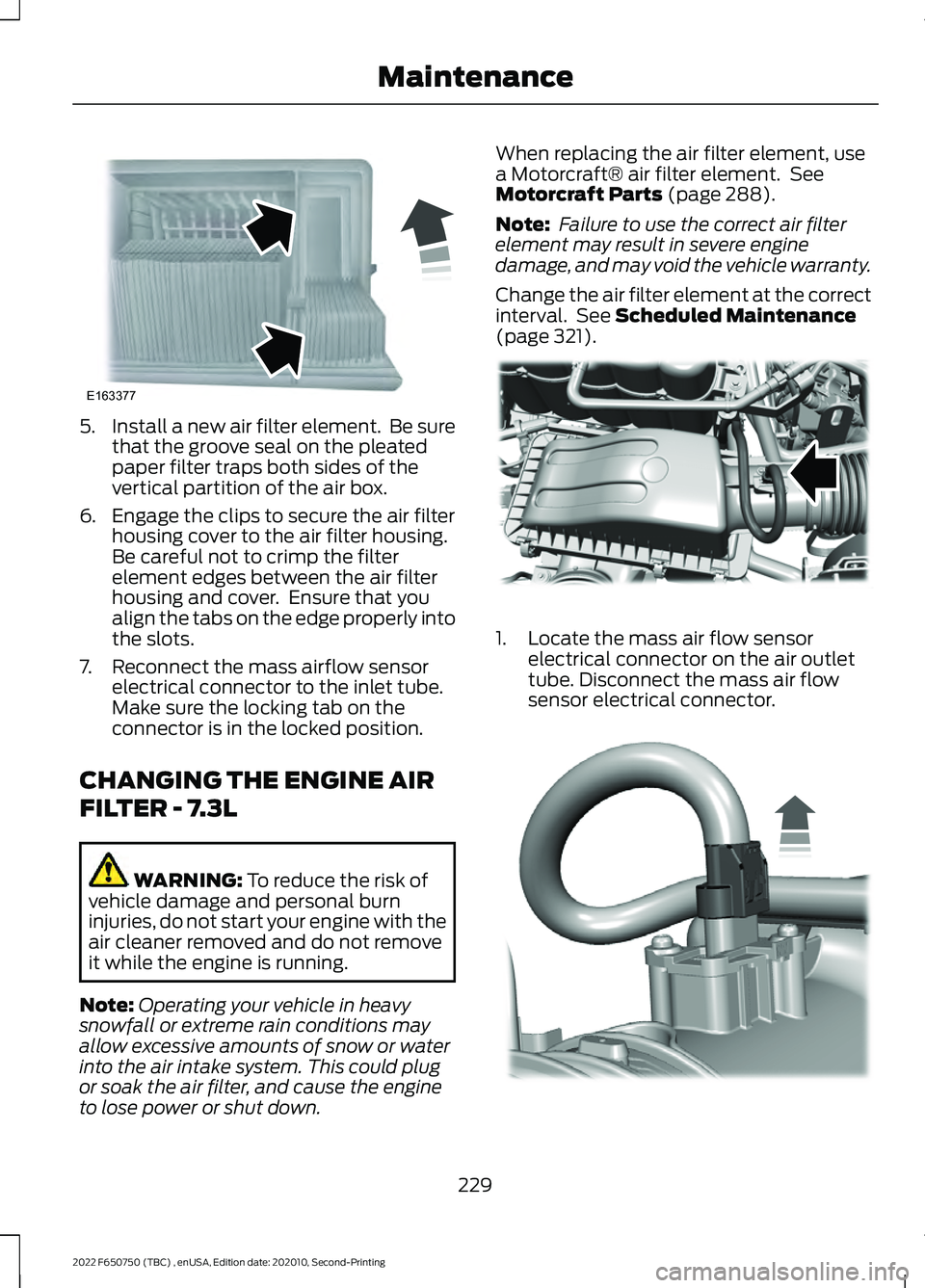
5.
Install a new air filter element. Be sure
that the groove seal on the pleated
paper filter traps both sides of the
vertical partition of the air box.
6. Engage the clips to secure the air filter housing cover to the air filter housing.
Be careful not to crimp the filter
element edges between the air filter
housing and cover. Ensure that you
align the tabs on the edge properly into
the slots.
7. Reconnect the mass airflow sensor electrical connector to the inlet tube.
Make sure the locking tab on the
connector is in the locked position.
CHANGING THE ENGINE AIR
FILTER - 7.3L WARNING: To reduce the risk of
vehicle damage and personal burn
injuries, do not start your engine with the
air cleaner removed and do not remove
it while the engine is running.
Note: Operating your vehicle in heavy
snowfall or extreme rain conditions may
allow excessive amounts of snow or water
into the air intake system. This could plug
or soak the air filter, and cause the engine
to lose power or shut down. When replacing the air filter element, use
a Motorcraft® air filter element. See
Motorcraft Parts
(page 288).
Note: Failure to use the correct air filter
element may result in severe engine
damage, and may void the vehicle warranty.
Change the air filter element at the correct
interval. See
Scheduled Maintenance
(page 321). 1. Locate the mass air flow sensor
electrical connector on the air outlet
tube. Disconnect the mass air flow
sensor electrical connector. 229
2022 F650750 (TBC) , enUSA, Edition date: 202010, Second-Printing MaintenanceE163377 E317615 E317616
Page 234 of 379
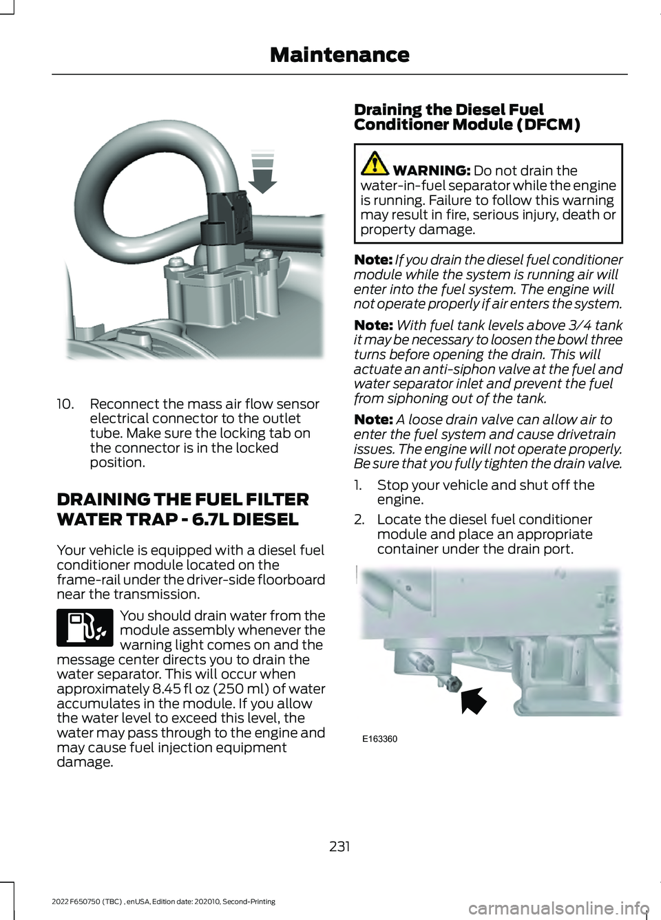
10. Reconnect the mass air flow sensor
electrical connector to the outlet
tube. Make sure the locking tab on
the connector is in the locked
position.
DRAINING THE FUEL FILTER
WATER TRAP - 6.7L DIESEL
Your vehicle is equipped with a diesel fuel
conditioner module located on the
frame-rail under the driver-side floorboard
near the transmission. You should drain water from the
module assembly whenever the
warning light comes on and the
message center directs you to drain the
water separator. This will occur when
approximately 8.45 fl oz (250 ml) of water
accumulates in the module. If you allow
the water level to exceed this level, the
water may pass through to the engine and
may cause fuel injection equipment
damage. Draining the Diesel Fuel
Conditioner Module (DFCM) WARNING: Do not drain the
water-in-fuel separator while the engine
is running. Failure to follow this warning
may result in fire, serious injury, death or
property damage.
Note: If you drain the diesel fuel conditioner
module while the system is running air will
enter into the fuel system. The engine will
not operate properly if air enters the system.
Note: With fuel tank levels above 3⁄4 tank
it may be necessary to loosen the bowl three
turns before opening the drain. This will
actuate an anti-siphon valve at the fuel and
water separator inlet and prevent the fuel
from siphoning out of the tank.
Note: A loose drain valve can allow air to
enter the fuel system and cause drivetrain
issues. The engine will not operate properly.
Be sure that you fully tighten the drain valve.
1. Stop your vehicle and shut off the engine.
2. Locate the diesel fuel conditioner module and place an appropriate
container under the drain port. 231
2022 F650750 (TBC) , enUSA, Edition date: 202010, Second-Printing MaintenanceE317619 E163360