tow FORD F SERIES MOTORHOME AND COMMERCIAL CHASSIS 2001 10.G Owners Manual
[x] Cancel search | Manufacturer: FORD, Model Year: 2001, Model line: F SERIES MOTORHOME AND COMMERCIAL CHASSIS, Model: FORD F SERIES MOTORHOME AND COMMERCIAL CHASSIS 2001 10.GPages: 104, PDF Size: 1.32 MB
Page 2 of 104
The following warning may be required by California law:
CALIFORNIA Proposition 65 Warning
WARNING:Engine exhaust, some of its constituents, and
certain vehicle components contain or emit chemicals known to
the State of California to cause cancer and birth defects or other
reproductive harm. In addition, certain fluids contained in vehicles and
certain products of component wear contain or emit chemicals known
to the State of California to cause cancer and birth defects or other
reproductive harm.
ICONS
Indicates a safety alert. Read the
following section onWarnings.
Indicates vehicle information related
to recycling and other
environmental concerns will follow.
Correct vehicle usage and the
authorized disposal of waste
cleaning and lubrication materials are significant steps towards
protecting the environment.
Indicates a message regarding child
safety restraints. Refer toSeating
and safety restraintsfor more
information.
Indicates that this Owner Guide
contains information on this subject.
Please refer to the Index to locate
the appropriate section which will
provide you more information.
Introduction
2
Page 8 of 104
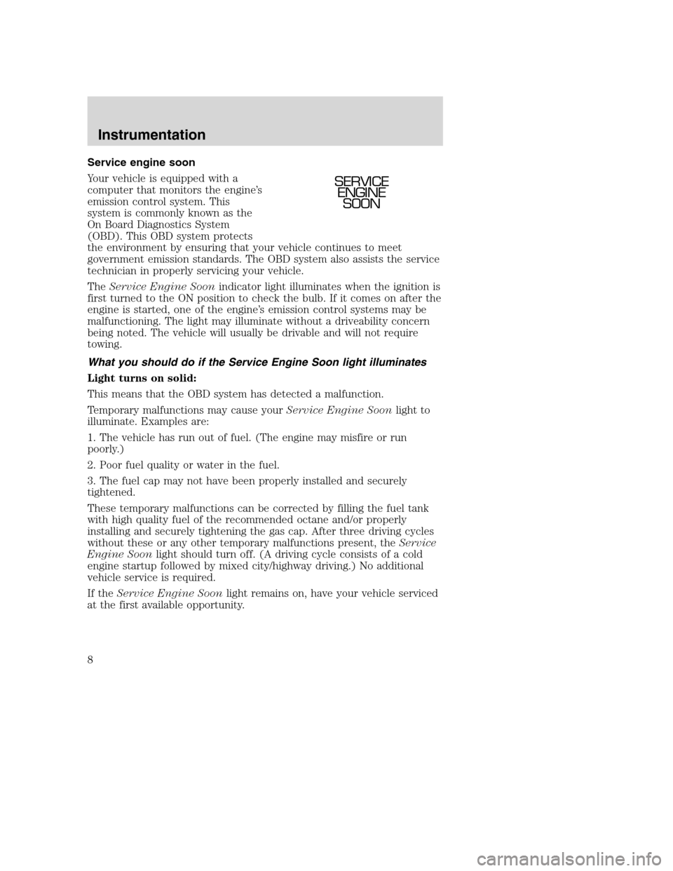
Service engine soon
Your vehicle is equipped with a
computer that monitors the engine’s
emission control system. This
system is commonly known as the
On Board Diagnostics System
(OBD). This OBD system protects
the environment by ensuring that your vehicle continues to meet
government emission standards. The OBD system also assists the service
technician in properly servicing your vehicle.
TheService Engine Soonindicator light illuminates when the ignition is
first turned to the ON position to check the bulb. If it comes on after the
engine is started, one of the engine’s emission control systems may be
malfunctioning. The light may illuminate without a driveability concern
being noted. The vehicle will usually be drivable and will not require
towing.
What you should do if the Service Engine Soon light illuminates
Light turns on solid:
This means that the OBD system has detected a malfunction.
Temporary malfunctions may cause yourService Engine Soonlight to
illuminate. Examples are:
1. The vehicle has run out of fuel. (The engine may misfire or run
poorly.)
2. Poor fuel quality or water in the fuel.
3. The fuel cap may not have been properly installed and securely
tightened.
These temporary malfunctions can be corrected by filling the fuel tank
with high quality fuel of the recommended octane and/or properly
installing and securely tightening the gas cap. After three driving cycles
without these or any other temporary malfunctions present, theService
Engine Soonlight should turn off. (A driving cycle consists of a cold
engine startup followed by mixed city/highway driving.) No additional
vehicle service is required.
If theService Engine Soonlight remains on, have your vehicle serviced
at the first available opportunity.
SERVICE
ENGINE
SOON
Instrumentation
8
Page 15 of 104
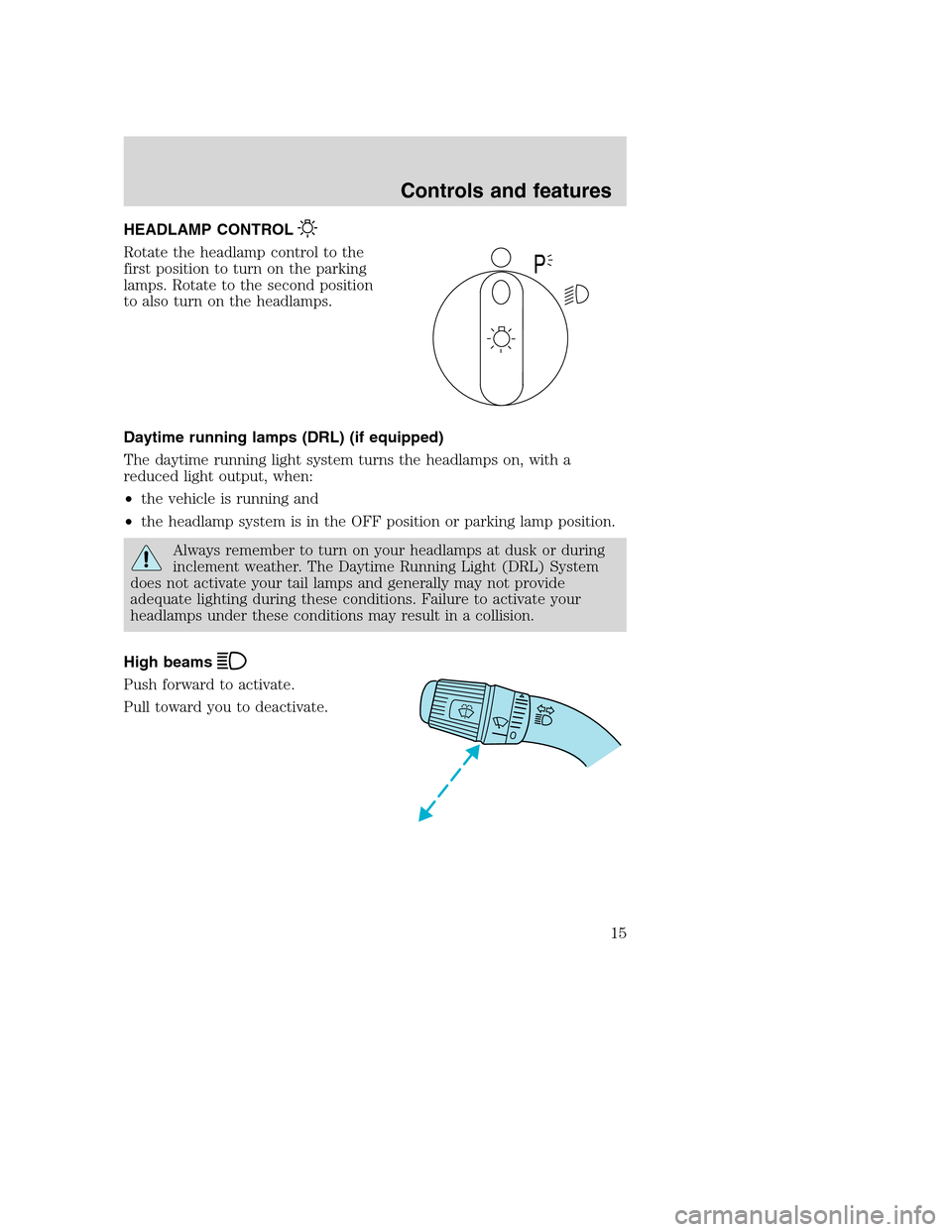
HEADLAMP CONTROL
Rotate the headlamp control to the
first position to turn on the parking
lamps. Rotate to the second position
to also turn on the headlamps.
Daytime running lamps (DRL) (if equipped)
The daytime running light system turns the headlamps on, with a
reduced light output, when:
•the vehicle is running and
•the headlamp system is in the OFF position or parking lamp position.
Always remember to turn on your headlamps at dusk or during
inclement weather. The Daytime Running Light (DRL) System
does not activate your tail lamps and generally may not provide
adequate lighting during these conditions. Failure to activate your
headlamps under these conditions may result in a collision.
High beams
Push forward to activate.
Pull toward you to deactivate.
P
Controls and features
15
Page 16 of 104
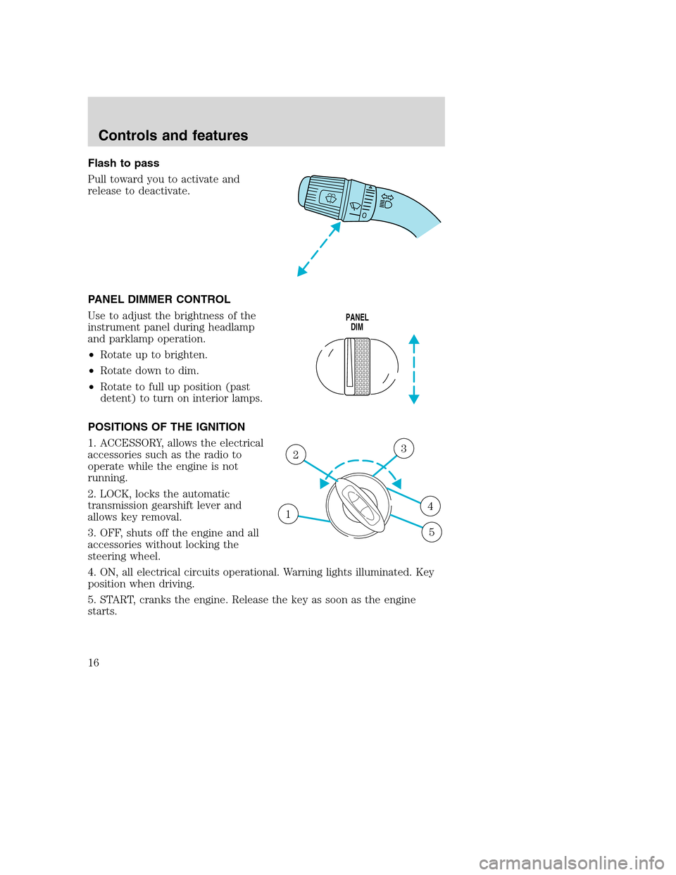
Flash to pass
Pull toward you to activate and
release to deactivate.
PANEL DIMMER CONTROL
Use to adjust the brightness of the
instrument panel during headlamp
and parklamp operation.
•Rotate up to brighten.
•Rotate down to dim.
•Rotate to full up position (past
detent) to turn on interior lamps.
POSITIONS OF THE IGNITION
1. ACCESSORY, allows the electrical
accessories such as the radio to
operate while the engine is not
running.
2. LOCK, locks the automatic
transmission gearshift lever and
allows key removal.
3. OFF, shuts off the engine and all
accessories without locking the
steering wheel.
4. ON, all electrical circuits operational. Warning lights illuminated. Key
position when driving.
5. START, cranks the engine. Release the key as soon as the engine
starts.
PANEL
DIM
1
23
4
5
Controls and features
16
Page 33 of 104
•towing a trailer up or down steep hills.
•additional engine downhill braking is desired. If towing a trailer, refer
toDriving while you towin theTrailer towingsection.
To return to
(Overdrive) mode, press the transmission control switch
(TCS). The TCIL (the word OFF) will no longer be illuminated.
Each time the vehicle is started, the transmission will automatically
return to normal overdrive mode.
Every time the vehicle is shut off and restarted, you must press the
transmission control switch to cancel overdrive operation if driving in
overdrive is not desired.
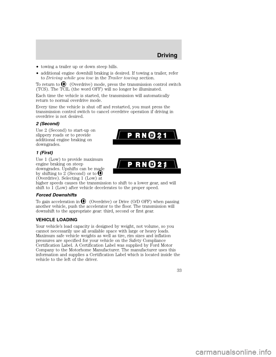
2 (Second)
Use 2 (Second) to start-up on
slippery roads or to provide
additional engine braking on
downgrades.
1 (First)
Use 1 (Low) to provide maximum
engine braking on steep
downgrades. Upshifts can be made
by shifting to 2 (Second) or to
(Overdrive). Selecting 1 (Low) at
higher speeds causes the transmission to shift to a lower gear, and will
shift to 1 (Low) after vehicle decelerates to the proper speed.
Forced Downshifts
To gain acceleration in(Overdrive) or Drive (O/D OFF) when passing
another vehicle, push the accelerator to the floor. The transmission will
downshift to the appropriate gear: third, second or first gear.
VEHICLE LOADING
Your vehicle’s load capacity is designed by weight, not volume, so you
cannot necessarily use all available space with large or heavy loads.
Maximum safe vehicle weights as well as tire, rim sizes and inflation
pressures are specified for your vehicle on the Safety Compliance
Certification Label. A Certification Label was supplied by Ford Motor
Company to the Motorhome Manufacturer. The manufacturer uses this
information and supplies a Certification Label which is located inside the
vehicle to the left of the driver.
Driving
33
Page 34 of 104
Before loading a vehicle, familiarize yourself with the following terms:
•Base Curb Weight:Weight of the vehicle including any standard
equipment, fluids, lubricants, etc. It does not include passengers or
aftermarket equipment.
•Payload:Combined maximum allowable weight of cargo, passengers
and optional equipment. The payload equals the gross vehicle weight
rating minus base curb weight.
•GVW (Gross Vehicle Weight):Base curb weight plus payload
weight. The GVW is not a limit or a specification.
•GVWR (Gross Vehicle Weight Rating):Maximum total weight of
the base vehicle, passengers, optional equipment and cargo. The
GVWR is specific to each vehicle and is listed on the Certification
Label, located near the driver’s seat or on the driver’s door pillar.
•GAWR (Gross Axle Weight Rating):Carrying capacity for each axle
system. The GAWR is specific to each vehicle and is listed on the
Certification Label, located near the driver’s seat or on the driver’s
door pillar.
•GCWR (Gross Combined Weight Rating):Maximum combined
weight of towing vehicle (including passengers and cargo) and the
trailer.
•Maximum Trailer Weight Rating:Maximum weight of a trailer the
loaded vehicle (including passengers and cargo) is permitted to tow.
The maximum trailer weight rating is determined by subtracting the
vehicle curb weight for each engine/transmission combination, any
required option weight for trailer towing and the weight of the driver
from the GCWR for the towing vehicle.
•Trailer Weight Range:Specified weight range that the trailer must
fall within that ranges from zero to the maximum trailer weight rating.
Remember to figure in the tongue load of your loaded trailer when
figuring the total weight.
Do not exceed the GVWR or the GAWR specified on the
certification label.
Do not use replacement tires with lower weight capacities than the
originals because they may lower the vehicle’s GVWR and GAWR
limitations. Replacement tires with a higher weight limit than the
originals do not increase the GVWR and GAWR limitations.
Driving
34
Page 35 of 104

Calculating the load your vehicle can carry/tow
1. Use the appropriate maximum gross combined weight rating (GCWR)
chart to find the maximum GCWR for your type engine and rear axle
ratio.
2. Weigh your vehicle as you customarily operate the vehicle without
cargo. To obtain correct weights, try taking your vehicle to a shipping
company or an inspection station for trucks.
3. Subtract your loaded vehicle weight from the maximum GCWR on the
following charts. This is the maximum combined cargo and trailer weight
your vehicle can carry/tow and must fall below the maximum shown
under maximum trailer weight on the chart. Refer to the definition of
Maximum Trailer Weight below Vehicle Loading in this chapter to
determine the maximum trailer weight permitted for a loaded vehicle.
TRAILER TOWING
Your vehicle may tow a class I, II or III trailer provided the maximum
trailer weight is less than or equal to the maximum trailer weight listed
for your engine and rear axle ratio on the following chart:
GCWR (Gross Combined Weight Rating)/Trailer Weights
EngineRear
axle
ratioMaximum
GCWR - kg
(lbs.)Trailer weight
range - kg
(lbs.)
(0-Maximum)Maximum Frontal
Area of Trailer -
m
2(ft2)
6.8L 5.3811 794
(26 000)0-4 763
(0-10 000)5.6 (60)
For high altitude operation reduce GCW by 2% per 300 meters
(1 000 ft) elevation. To determine the maximum trailer weight
designed for your particular vehicle as equipped, follow the section
Calculating the load your vehicle can carry/towearlier in this
chapter.
Preparing to tow
Use the proper equipment for towing a trailer, and make sure it is
properly attached to your vehicle. See your dealer or a reliable trailer
dealer if you require assistance.
Hitches
You must distribute the load in your trailer so that 10 – 15% of the total
weight of the trailer is on the tongue.
Driving
35
Page 36 of 104
Load equalizing hitch
When hooking up a trailer using a load equalizing hitch, always use the
following procedure:
1. Park the unloaded vehicle on a level surface. With the ignition on and
all doors closed, allow the vehicle to stand for several minutes so that it
can level.
2. Measure the height of a reference point on the front and rear bumpers
at the center of the vehicle.
3. Attach the trailer to the vehicle and adjust the hitch equalizers so that
the front bumper height is within 0–13 mm (0.5 in) of the reference
point. After proper adjustment, the rear bumper should be no higher
than in Step 3.
Adjusting an equalizing hitch so the rear bumper of the vehicle
is lower or higher than it was unloaded will defeat the function
of the load equalizing hitch and may cause unpredictable handling.
Safety chains
Always connect the trailer’s safety chains to the frame or hook retainers
of the vehicle. To connect the trailer’s safety chains, cross the chains
under the trailer tongue and allow slack for turning corners.
If you use a rental trailer, follow the instructions that the rental agency
gives to you.
Do not attach safety chains to the bumper.
Trailer brakes
Electric brakes and manual, automatic or surge-type brakes are safe if
installed properly and adjusted to the manufacturer’s specifications. The
trailer brakes must meet local and Federal regulations.
Do not connect a trailer’s hydraulic brake system directly to your
vehicle’s brake system. Your vehicle may not have enough
braking power and your chances of having a collision greatly increase.
The towing vehicle braking system is rated for operation at the GVWR,
not the GCWR.
Driving
36
Page 37 of 104
Separate functioning brake systems are required for safe control of
towed vehicles and trailers weighing more than 680 kg (1 500 lbs) when
loaded.
Trailer lamps
Trailer lamps are required on most towed vehicles. Make sure your
trailer lamps conform to local and Federal regulations. See your dealer or
trailer rental agency for proper instructions and equipment for hooking
up trailer lamps.
Driving while you tow
When towing a trailer:
•Ensure that you turn off your speed control. The speed control may
shut off automatically when you are towing on long, steep grades.
•Consult your local motor vehicle speed regulations for towing a trailer.
•Use a lower gear when towing up or down steep hills. This will
eliminate excessive downshifting and upshifting for optimum fuel
economy and transmission cooling.
•Anticipate stops and brake gradually.
Servicing after towing
If you tow a trailer for long distances, your vehicle will require more
frequent service intervals. Refer to your scheduled maintenance guide for
more information.
Trailer towing tips
•Practice turning, stopping and backing up before starting on a trip to
get the feel of the vehicle trailer combination. When turning, make
wider turns so the trailer wheels will clear curbs and other obstacles.
•Allow more distance for stopping with a trailer attached.
•The trailer tongue weight should be 10% of the loaded trailer weight.
•After you have traveled 80 km (50 miles), thoroughly check your
hitch, electrical connections and trailer wheel lug nuts.
•When stopped in traffic for long periods of time in hot weather, place
the gearshift in P (Park) and increase idle speed. This aids engine
cooling and air conditioner efficiency.
•Vehicles with trailers should not be parked on a grade. If you must
park on a grade, place wheel chocks under the trailer’s wheels.
Driving
37
Page 43 of 104
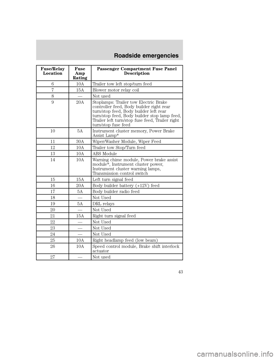
Fuse/Relay
LocationFuse
Amp
RatingPassenger Compartment Fuse Panel
Description
6 10A Trailer tow left stop/turn feed
7 15A Blower motor relay coil
8 — Not used
9 20A Stoplamps: Trailer tow Electric Brake
controller feed, Body builder right rear
turn/stop feed, Body builder left rear
turn/stop feed, Body builder stop lamp feed,
Trailer left turn/stop fuse feed, Trailer right
turn/stop fuse feed
10 5A Instrument cluster memory, Power Brake
Assist Lamp*
11 30A Wiper/Washer Module, Wiper Feed
12 10A Trailer tow Stop/Turn feed
13 10A ABS Module
14 10A Warning chime module, Power brake assist
module*, Instrument cluster power,
Instrument cluster warning lamps,
Transmission control switch
15 15A Left turn signal feed
16 20A Body builder battery (+12V) feed
17 5A Body builder radio feed
18 — Not Used
19 5A DRL relays
20 — Not Used
21 15A Right turn signal feed
22 — Not Used
23 — Not Used
24 — Not Used
25 10A Right headlamp feed (low beam)
26 10A Speed control module, Brake shift interlock
actuator
27 — Not used
Roadside emergencies
43