FORD F SERIES MOTORHOME AND COMMERCIAL CHASSIS 2008 11.G Owners Manual
Manufacturer: FORD, Model Year: 2008, Model line: F SERIES MOTORHOME AND COMMERCIAL CHASSIS, Model: FORD F SERIES MOTORHOME AND COMMERCIAL CHASSIS 2008 11.GPages: 130, PDF Size: 1.24 MB
Page 111 of 130
On board diagnostics (OBD-II)
Your vehicle is equipped with a computer that monitors the engine’s
emission control system. This system is commonly known as the On
Board Diagnostics System (OBD-II). The OBD-II system protects the
environment by ensuring that your vehicle continues to meet
government emission standards. The OBD-II system also assists your
authorized dealer in properly servicing your vehicle. When theService
engine soon
indicator illuminates, the OBD-II system has detected
a malfunction. Temporary malfunctions may cause theService engine
soon
indicator to illuminate. Examples are:
1. The vehicle has run out of fuel—the engine may misfire or run poorly.
2. Poor fuel quality or water in the fuel—the engine may misfire or run
poorly.
3. The fuel cap may not have been securely tightened. SeeFuel filler
capin this chapter.
4. Driving through deep water—the electrical system may be wet.
These temporary malfunctions can be corrected by filling the fuel tank
with good quality fuel, properly tightening the fuel cap or letting the
electrical system dry out. After three driving cycles without these or any
other temporary malfunctions present, theService engine soon
indicator should stay off the next time the engine is started. A driving
cycle consists of a cold engine startup followed by mixed city/highway
driving. No additional vehicle service is required.
If theService engine soon
indicator remains on, have your vehicle
serviced at the first available opportunity. Although some malfunctions
detected by the OBD-II may not have symptoms that are apparent,
continued driving with theService engine soon
indicator on can
result in increased emissions, lower fuel economy, reduced engine and
transmission smoothness, and lead to more costly repairs.
2008 Motorhome(mot)
Supplement
USA(fus)
Maintenance and Specifications
111
Page 112 of 130
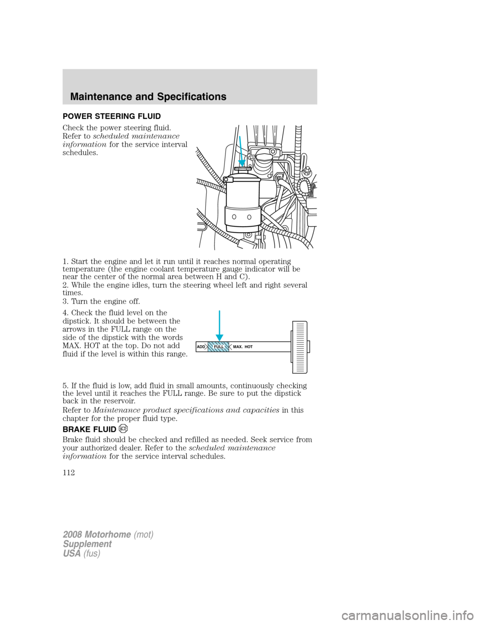
POWER STEERING FLUID
Check the power steering fluid.
Refer toscheduled maintenance
informationfor the service interval
schedules.
1. Start the engine and let it run until it reaches normal operating
temperature (the engine coolant temperature gauge indicator will be
near the center of the normal area between H and C).
2. While the engine idles, turn the steering wheel left and right several
times.
3. Turn the engine off.
4. Check the fluid level on the
dipstick. It should be between the
arrows in the FULL range on the
side of the dipstick with the words
MAX. HOT at the top. Do not add
fluid if the level is within this range.
5. If the fluid is low, add fluid in small amounts, continuously checking
the level until it reaches the FULL range. Be sure to put the dipstick
back in the reservoir.
Refer toMaintenance product specifications and capacitiesin this
chapter for the proper fluid type.
BRAKE FLUID
Brake fluid should be checked and refilled as needed. Seek service from
your authorized dealer. Refer to thescheduled maintenance
informationfor the service interval schedules.
ADD MAX. HOTFULL
2008 Motorhome(mot)
Supplement
USA(fus)
Maintenance and Specifications
112
Page 113 of 130
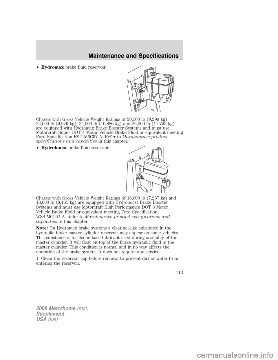
•Hydromaxbrake fluid reservoir
Chassis with Gross Vehicle Weight Ratings of 20,500 lb (9,299 kg),
22,000 lb (9,979 kg), 24,000 lb (10,886 kg) and 26,000 lb (11,793 kg)
are equipped with Hydromax Brake Booster Systems and must use
Motorcraft Super DOT 4 Motor Vehicle Brake Fluid or equivalent meeting
Ford Specification ESD-M6C57-A. Refer toMaintenance product
specifications and capacitiesin this chapter.
•Hydroboostbrake fluid reservoir
Chassis with Gross Vehicle Weight Ratings of 16,000 lb (7,257 kg) and
18,000 lb (8,165 kg) are equipped with Hydroboost Brake Booster
Systems and must use Motorcraft High Performance DOT 3 Motor
Vehicle Brake Fluid or equivalent meeting Ford Specification
WSS-M6C62-A. Refer toMaintenance product specifications and
capacitiesin this chapter.
Note:On Hydromax brake systems a clear gel-like substance in the
hydraulic brake master cylinder reservoir may appear on some vehicles.
This substance is a silicone base lubricant used during assembly of the
master cylinder. It will float on top of the brake hydraulic fluid in the
master cylinder. This condition is normal and in no way affects the
operation of the brake system. It does not require any service.
1. Clean the reservoir cap before removal to prevent dirt or water from
entering the reservoir.
2008 Motorhome(mot)
Supplement
USA(fus)
Maintenance and Specifications
113
Page 114 of 130
2. Visually inspect the fluid level.
3. If necessary, add brake fluid from a clean un-opened container until
the level reaches MAX. Do not fill above this line.
4. Use only a brake fluid listed previously (DOT 3 or Super DOT 4
depending on brake system) and that is certified to meet Ford
specifications. Refer toMaintenance product specifications and
capacitiesin this chapter.
WARNING:Carefully read cautionary information on product
label. For MEDICAL EMERGENCY INFORMATION contact a
physician or Poison Control Center immediately; on Ford-Motorcraft
products call: 1-800-959-3673 (FORD). Failure to follow these
instructions may result in personal injury.
WARNING:Use of any brake fluid other than that indicated for
your brake system will cause permanent damage.
WARNING:Do not let the reservoir for the master cylinder run
dry. This may cause the brakes to fail.
Brake system fluid should be replaced on a regular basis to maintain
optimum braking performance, especially under heavy-duty driving
conditions such as frequent steep grades or heavy towing loads. Refer to
scheduled maintenance informationfor the service interval schedules.
2008 Motorhome(mot)
Supplement
USA(fus)
Maintenance and Specifications
114
Page 115 of 130
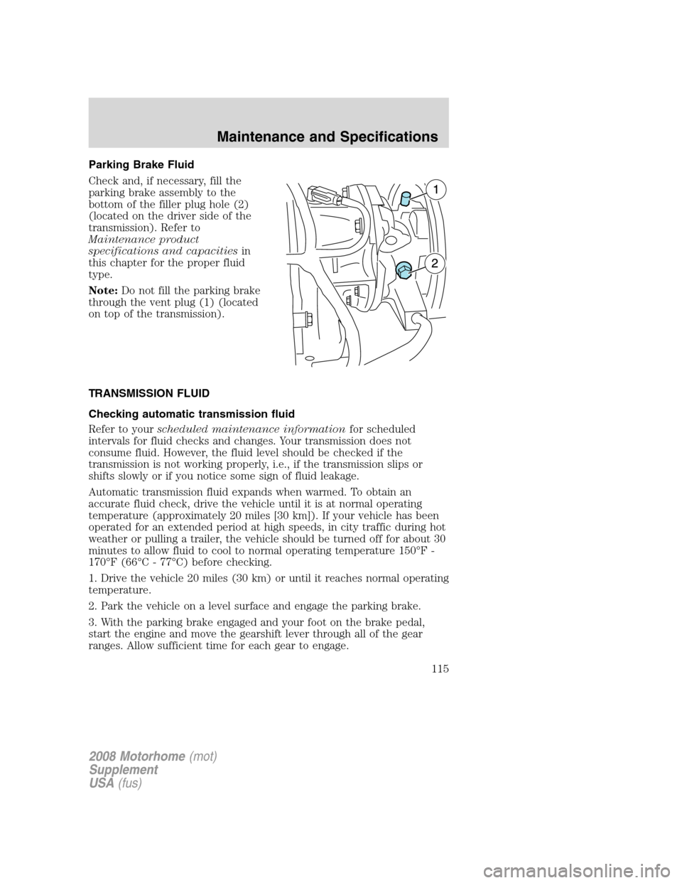
Parking Brake Fluid
Check and, if necessary, fill the
parking brake assembly to the
bottom of the filler plug hole (2)
(located on the driver side of the
transmission). Refer to
Maintenance product
specifications and capacitiesin
this chapter for the proper fluid
type.
Note:Do not fill the parking brake
through the vent plug (1) (located
on top of the transmission).
TRANSMISSION FLUID
Checking automatic transmission fluid
Refer to yourscheduled maintenance informationfor scheduled
intervals for fluid checks and changes. Your transmission does not
consume fluid. However, the fluid level should be checked if the
transmission is not working properly, i.e., if the transmission slips or
shifts slowly or if you notice some sign of fluid leakage.
Automatic transmission fluid expands when warmed. To obtain an
accurate fluid check, drive the vehicle until it is at normal operating
temperature (approximately 20 miles [30 km]). If your vehicle has been
operated for an extended period at high speeds, in city traffic during hot
weather or pulling a trailer, the vehicle should be turned off for about 30
minutes to allow fluid to cool to normal operating temperature 150°F -
170°F (66°C - 77°C) before checking.
1. Drive the vehicle 20 miles (30 km) or until it reaches normal operating
temperature.
2. Park the vehicle on a level surface and engage the parking brake.
3. With the parking brake engaged and your foot on the brake pedal,
start the engine and move the gearshift lever through all of the gear
ranges. Allow sufficient time for each gear to engage.
2008 Motorhome(mot)
Supplement
USA(fus)
Maintenance and Specifications
115
Page 116 of 130
4. Latch the gearshift lever in P (Park) and leave the engine running.
5. Remove the dipstick, wiping it clean with a clean, dry lint free rag. If
necessary, refer toIdentifying components in the engine compartment
in this chapter for the location of the dipstick.
6. Install the dipstick making sure it is fully seated in the filler tube.
7. Remove the dipstick and inspect the fluid level. The fluid should be in
the designated area for normal operating temperature or ambient
temperature.
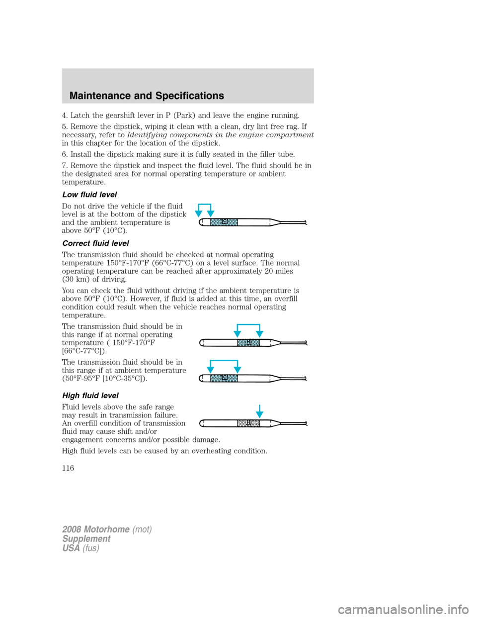
Low fluid level
Do not drive the vehicle if the fluid
level is at the bottom of the dipstick
and the ambient temperature is
above 50°F (10°C).
Correct fluid level
The transmission fluid should be checked at normal operating
temperature 150°F-170°F (66°C-77°C) on a level surface. The normal
operating temperature can be reached after approximately 20 miles
(30 km) of driving.
You can check the fluid without driving if the ambient temperature is
above 50°F (10°C). However, if fluid is added at this time, an overfill
condition could result when the vehicle reaches normal operating
temperature.
The transmission fluid should be in
this range if at normal operating
temperature ( 150°F-170°F
[66°C-77°C]).
The transmission fluid should be in
this range if at ambient temperature
(50°F-95°F [10°C-35°C]).
High fluid level
Fluid levels above the safe range
may result in transmission failure.
An overfill condition of transmission
fluid may cause shift and/or
engagement concerns and/or possible damage.
High fluid levels can be caused by an overheating condition.
2008 Motorhome(mot)
Supplement
USA(fus)
Maintenance and Specifications
116
Page 117 of 130
Adjusting automatic transmission fluid levels
Before adding any fluid, make sure the correct type is used. The type of
fluid used is normally indicated on the dipstick and also in the
Maintenance product specifications and capacitiessection in this
chapter.
Use of a non-approved automatic transmission fluid may cause
internal transmission component damage.
If necessary, add fluid in 1/2 pint (250 ml) increments through the filler
tube until the level is correct.
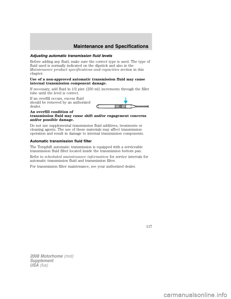
If an overfill occurs, excess fluid
should be removed by an authorized
dealer.
An overfill condition of
transmission fluid may cause shift and/or engagement concerns
and/or possible damage.
Do not use supplemental transmission fluid additives, treatments or
cleaning agents. The use of these materials may affect transmission
operation and result in damage to internal transmission components.
Automatic transmission fluid filter
The Torqshift automatic transmission is equipped with a serviceable
transmission fluid filter located inside the transmission bottom pan.
Refer toscheduled maintenance informationfor service intervals for
automatic transmission fluid and transmission filter.
For transmission filter maintenance, see your authorized dealer.
2008 Motorhome(mot)
Supplement
USA(fus)
Maintenance and Specifications
117
Page 118 of 130
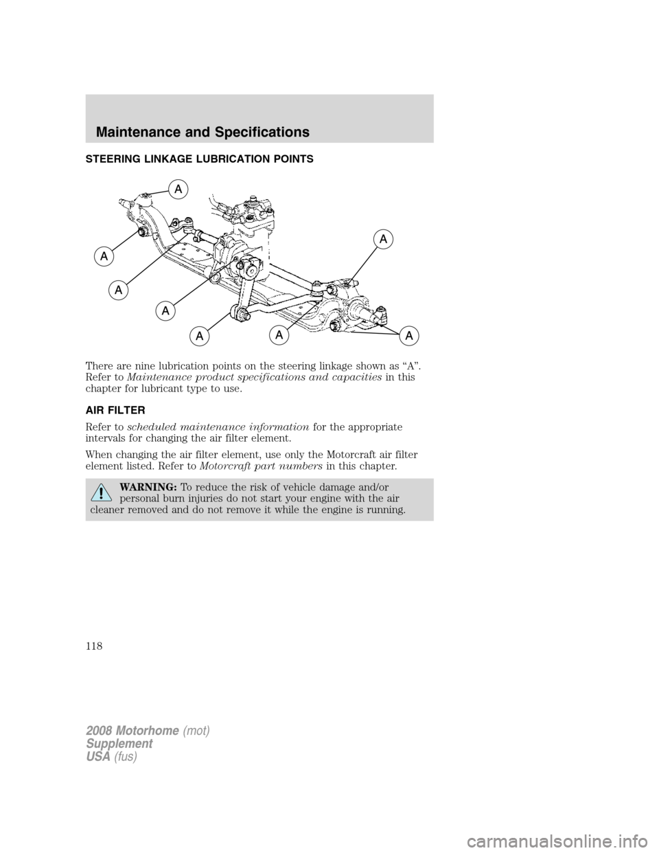
STEERING LINKAGE LUBRICATION POINTS
There are nine lubrication points on the steering linkage shown as “A”.
Refer toMaintenance product specifications and capacitiesin this
chapter for lubricant type to use.
AIR FILTER
Refer toscheduled maintenance informationfor the appropriate
intervals for changing the air filter element.
When changing the air filter element, use only the Motorcraft air filter
element listed. Refer toMotorcraft part numbersin this chapter.
WARNING:To reduce the risk of vehicle damage and/or
personal burn injuries do not start your engine with the air
cleaner removed and do not remove it while the engine is running.
2008 Motorhome(mot)
Supplement
USA(fus)
Maintenance and Specifications
118
Page 119 of 130
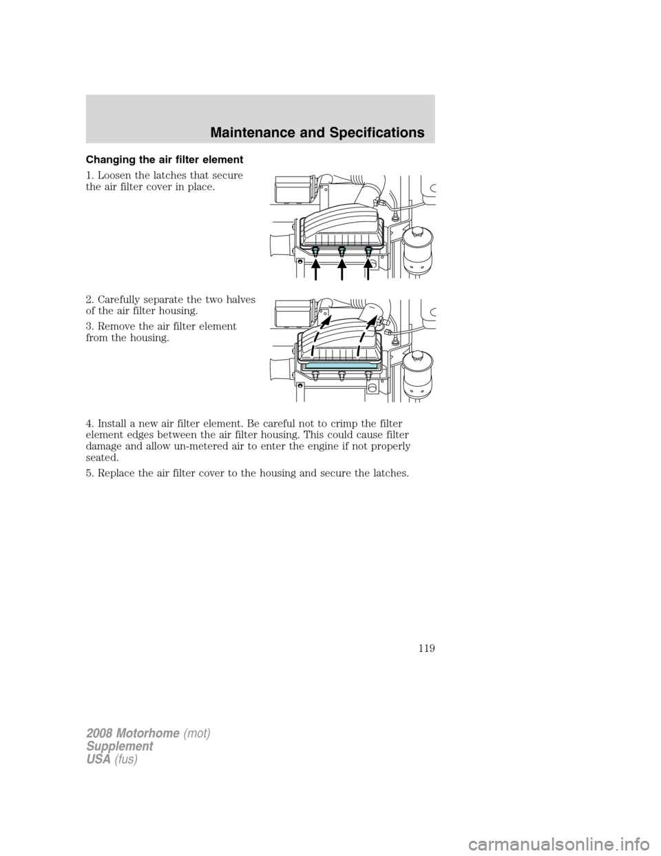
Changing the air filter element
1. Loosen the latches that secure
the air filter cover in place.
2. Carefully separate the two halves
of the air filter housing.
3. Remove the air filter element
from the housing.
4. Install a new air filter element. Be careful not to crimp the filter
element edges between the air filter housing. This could cause filter
damage and allow un-metered air to enter the engine if not properly
seated.
5. Replace the air filter cover to the housing and secure the latches.
2008 Motorhome(mot)
Supplement
USA(fus)
Maintenance and Specifications
119
Page 120 of 130
MOTORCRAFT PART NUMBERS
Component 6.8L V10 engine
Air filter element FA-1782
Battery BXT-65-750
Fuel filter FG-872
Oil filter FL-820-S
PCV valve
1
Spark plugs2
Transmission fluid filter FT-175
1The PCV valve is a critical emission component. It is one of the items
listed inscheduled maintenance informationand is essential to the
life and performance of your vehicle and to its emissions system.
For PCV valve replacement, see your authorized dealer. Refer to
scheduled maintenance informationfor the appropriate intervals for
changing the PCV valve.
Replace the PCV valve with one that meets Ford material and
design specifications for your vehicle, such as a Motorcraft or
equivalent replacement part. The customer warranty may be void
for any damage to the emissions system if such a PCV valve is not
used.
2For spark plug replacement, see your authorized dealer. Refer to
scheduled maintenance informationfor the appropriate intervals for
changing the spark plugs.
Replace the spark plugs with ones that meet Ford material and
design specifications for your vehicle, such as Motorcraft or
equivalent replacement parts. The customer warranty may be
void for any damage to the engine if such spark plugs are not
used.
2008 Motorhome(mot)
Supplement
USA(fus)
Maintenance and Specifications
120