warning light FORD F SERIES MOTORHOME AND COMMERCIAL CHASSIS 2012 12.G User Guide
[x] Cancel search | Manufacturer: FORD, Model Year: 2012, Model line: F SERIES MOTORHOME AND COMMERCIAL CHASSIS, Model: FORD F SERIES MOTORHOME AND COMMERCIAL CHASSIS 2012 12.GPages: 160, PDF Size: 1.22 MB
Page 25 of 160
INFORMATION ABOUT UNIFORM TIRE QUALITY GRADING
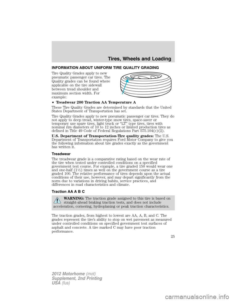
Tire Quality Grades apply to new
pneumatic passenger car tires. The
Quality grades can be found where
applicable on the tire sidewall
between tread shoulder and
maximum section width. For
example:
•Treadwear 200 Traction AA Temperature A
These Tire Quality Grades are determined by standards that the United
States Department of Transportation has set.
Tire Quality Grades apply to new pneumatic passenger car tires. They do
not apply to deep tread, winter-type snow tires, space-saver or
temporary use spare tires, light truck or “LT” type tires, tires with
nominal rim diameters of 10 to 12 inches or limited production tires as
defined in Title 49 Code of Federal Regulations Part 575.104(c)(2).
U.S. Department of Transportation-Tire quality grades:The U.S.
Department of Transportation requires Ford Motor Company to give you
the following information about tire grades exactly as the government
has written it.
Treadwear
The treadwear grade is a comparative rating based on the wear rate of
the tire when tested under controlled conditions on a specified
government test course. For example, a tire graded 150 would wear one
and one-half (1
12) times as well on the government course as a tire
graded 100. The relative performance of tires depends upon the actual
conditions of their use, however, and may depart significantly from the
norm due to variations in driving habits, service practices, and
differences in road characteristics and climate.
Traction AA A B C
WARNING:The traction grade assigned to this tire is based on
straight-ahead braking traction tests, and does not include
acceleration, cornering, hydroplaning or peak traction characteristics.
The traction grades, from highest to lowest are AA, A, B, and C. The
grades represent the tire’s ability to stop on wet pavement as measured
under controlled conditions on specified government test surfaces of
asphalt and concrete. A tire marked C may have poor traction
performance.
Tires, Wheels and Loading
25
2012 Motorhome(mot)
Supplement, 2nd Printing
USA(fus)
Page 27 of 160
•PSI:Pounds per square inch, a standard unit of air pressure.
•Cold inflation pressure:The tire pressure when the vehicle has
been stationary and out of direct sunlight for an hour or more and
prior to the vehicle being driven for 1 mile (1.6 km).
•Recommended inflation pressure:The cold inflation pressure found
on the Safety Compliance Certification Label. See the completed
vehicle’s owner’s guide for the location of the Safety Compliance
Certification Label.
•Bead area of the tire:Area of the tire next to the rim.
•Sidewall of the tire:Area between the bead area and the tread.
•Tread area of the tire:Area of the perimeter of the tire that
contacts the road when mounted on the vehicle.
•Rim:The metal support (wheel) for a tire or a tire and tube assembly
upon which the tire beads are seated.
INFLATING YOUR TIRES
Safe operation of your vehicle requires that your tires are properly
inflated. Remember that a tire can lose up to half of its air pressure
without appearing flat.
Every day before you drive, check your tires. If one looks lower than the
others, use a tire gauge to check pressure of all tires and adjust if
required.
At least once a month and before long trips, inspect each tire and check
the tire pressure with a tire gauge (including spare, if equipped). Inflate
all tires to the inflation pressure recommended by Ford Motor Company.
WARNING:Under-inflation is the most common cause of tire
failures and may result in severe tire cracking, tread separation
or “blowout”, with unexpected loss of vehicle control and increased
risk of injury. Under-inflation increases sidewall flexing and rolling
resistance, resulting in heat buildup and internal damage to the tire. It
also may result in unnecessary tire stress, irregular wear, loss of
vehicle control and accidents. A tire can lose up to half of its air
pressure and not appear to be flat!
You are strongly urged to buy a reliable tire pressure gauge, as automatic
service station gauges may be inaccurate. Ford recommends the use of a
digital or dial type tire pressure gauge rather than a stick type tire
pressure gauge.
Tires, Wheels and Loading
27
2012 Motorhome(mot)
Supplement, 2nd Printing
USA(fus)
Page 30 of 160
Tire inflation information
All tires with Steel Carcass Plies (if equipped):
This type of tire utilizes steel cords in the sidewalls. As such, they
cannot be treated like normal light truck tires. Tire service, including
adjusting tire pressure, must be performed by personnel trained,
supervised and equipped according to Federal Occupational Safety and
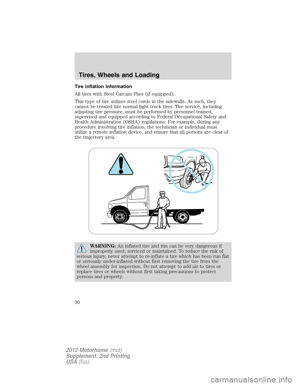
Health Administration (OSHA) regulations. For example, during any
procedure involving tire inflation, the technician or individual must
utilize a remote inflation device, and ensure that all persons are clear of
the trajectory area.
WARNING:An inflated tire and rim can be very dangerous if
improperly used, serviced or maintained. To reduce the risk of
serious injury, never attempt to re-inflate a tire which has been run flat
or seriously under-inflated without first removing the tire from the
wheel assembly for inspection. Do not attempt to add air to tires or
replace tires or wheels without first taking precautions to protect
persons and property.
Tires, Wheels and Loading
30
2012 Motorhome(mot)
Supplement, 2nd Printing
USA(fus)
Page 49 of 160
5. Install and adjust the tension in the weight distributing bars so that the
height of the front fender is approximately halfway between H1 and H2.
6. Check that the trailer is level. If not level, adjust the ball height
accordingly and repeat Steps 3–6.
WARNING:Do not adjust a weight-distributing hitch to any
position where the rear bumper of the vehicle is higher than it
was before attaching the trailer. Doing so will defeat the function of
the weight-distributing hitch, which may cause unpredictable handling,
and could result in serious personal injury.
Safety chains
Always connect the trailer’s safety chains to the frame or hook retainers
of the vehicle hitch. To connect the trailer’s safety chains, cross the
chains under the trailer tongue and allow slack for turning corners.
If you use a rental trailer, follow the instructions that the rental agency
gives to you.
Do not attach safety chains to the bumper.
Trailer brakes
Electric brakes and manual, automatic or surge-type brakes are safe if
installed properly and adjusted to the manufacturer’s specifications. The
trailer brakes must meet local and Federal regulations.
WARNING:Do not connect a trailer’s hydraulic brake system
directly to your vehicle’s brake system. Your vehicle may not
have enough braking power and your chances of having a collision
greatly increase.
The towing vehicle braking system is rated for operation at the
GVWR, not the GCWR.
Separate functioning brake systems are required for safe control
of towed vehicles and trailers weighing more than 1,500 lb
(680 kg) when loaded.
Trailer lamps
Trailer lamps are required on most towed vehicles. Make sure all running
lights, brake lights, turn signals and hazard lights are working. Contact
your authorized dealer or trailer rental agency for proper instructions
and equipment for hooking-up trailer lamps.
Tires, Wheels and Loading
49
2012 Motorhome(mot)
Supplement, 2nd Printing
USA(fus)
Page 51 of 160
STARTING
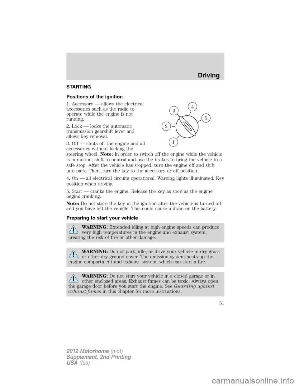
Positions of the ignition
1. Accessory — allows the electrical
accessories such as the radio to
operate while the engine is not
running.
2. Lock — locks the automatic
transmission gearshift lever and
allows key removal.
3. Off — shuts off the engine and all
accessories without locking the
steering wheel.Note:In order to switch off the engine while the vehicle
is in motion, shift to neutral and use the brakes to bring the vehicle to a
safe stop. After the vehicle has stopped, turn the engine off and shift
into park. Then, turn the key to the accessory or off position.
4. On — all electrical circuits operational. Warning lights illuminated. Key
position when driving.
5. Start — cranks the engine. Release the key as soon as the engine
begins cranking.
Note:Do not store the key in the ignition after the vehicle is turned off
and you have left the vehicle. This could cause a drain on the battery.
Preparing to start your vehicle
WARNING:Extended idling at high engine speeds can produce
very high temperatures in the engine and exhaust system,
creating the risk of fire or other damage.
WARNING:Do not park, idle, or drive your vehicle in dry grass
or other dry ground cover. The emission system heats up the
engine compartment and exhaust system, which can start a fire.
WARNING:Do not start your vehicle in a closed garage or in
other enclosed areas. Exhaust fumes can be toxic. Always open
the garage door before you start the engine. SeeGuarding against
exhaust fumesin this chapter for more instructions.
3
1
2
5
4
Driving
51
2012 Motorhome(mot)
Supplement, 2nd Printing
USA(fus)
Page 53 of 160
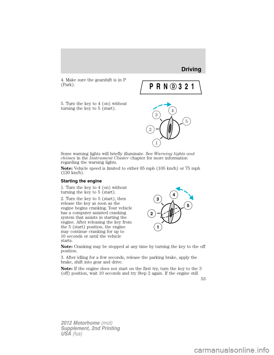
4. Make sure the gearshift is in P
(Park).
5. Turn the key to 4 (on) without
turning the key to 5 (start).
Some warning lights will briefly illuminate. SeeWarning lights and
chimesin theInstrument Clusterchapter for more information
regarding the warning lights.
Note:Vehicle speed is limited to either 65 mph (105 km/h) or 75 mph
(120 km/h).
Starting the engine
1. Turn the key to 4 (on) without
turning the key to 5 (start).
2. Turn the key to 5 (start), then
release the key as soon as the
engine begins cranking. Your vehicle
has a computer assisted cranking
system that assists in starting the
engine. After releasing the key from
the 5 (start) position, the engine
may continue cranking for up to
10 seconds or until the vehicle
starts.
Note:Cranking may be stopped at any time by turning the key to the off
position.
3. After idling for a few seconds, release the parking brake, apply the
brake, shift into gear and drive.
Note:If the engine does not start on the first try, turn the key to the 3
(off) position, wait 10 seconds and try Step 2 again. If the engine still
1
2
34
5
3
2
1
5
4
Driving
53
2012 Motorhome(mot)
Supplement, 2nd Printing
USA(fus)
Page 54 of 160
fails to start, press the accelerator to the floor and try Step 2 again,
keeping the accelerator on the floor until the engine begins to accelerate
above cranking speeds; this will allow the engine to crank with the fuel
shut off in case the engine is flooded with fuel.
Guarding against exhaust fumes
WARNING:If you smell exhaust fumes inside your vehicle, have
your dealer inspect your vehicle immediately. Do not drive if you
smell exhaust fumes.
Carbon monoxide is present in exhaust fumes. Take precautions to avoid
its dangerous effects.
Important ventilating information
If the engine is idling while the vehicle is stopped in an open area for
long periods of time, open the windows at least 1 inch (2.5 cm).
Adjust the heating or air conditioning (if equipped) to bring in fresh air.
Improve vehicle ventilation by keeping all air inlet vents clear of snow,
leaves and other debris.
BRAKES
Your service brakes are self-adjusting. Refer to thescheduled
maintenance informationfor scheduled maintenance.
Occasional brake noise is normal and often does not indicate a
performance concern with the vehicle’s brake system. In normal
operation, automotive brake systems may emit occasional or intermittent
squeal or groan noises when the brakes are applied. Such noises are
usually heard during the first few brake applications in the morning;
however, they may be heard at any time while braking and can be
aggravated by environmental conditions such as cold, heat, moisture,
road dust, salt or mud. If a “metal-to-metal,” “continuous grinding” or
“continuous squeal” sound is present while braking, the brake linings
may be worn-out and should be inspected by an authorized dealer.
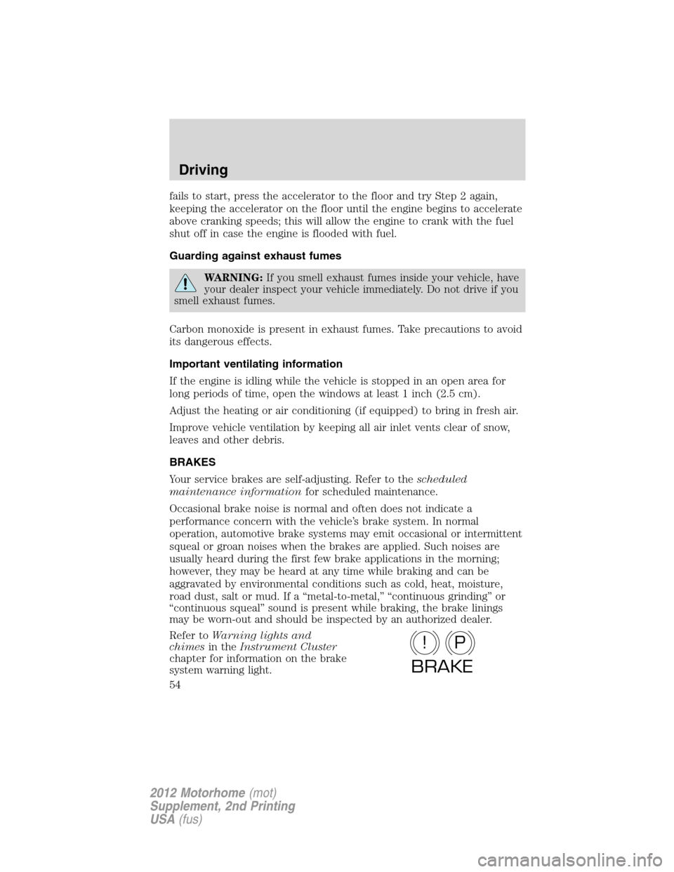
Refer toWarning lights and
chimesin theInstrument Cluster
chapter for information on the brake
system warning light.
P!
BRAKE
Driving
54
2012 Motorhome(mot)
Supplement, 2nd Printing
USA(fus)
Page 55 of 160
WARNING:If you are driving down a long or steep hill, shift to
a lower gear. Do not apply your brakes continuously, as they may
overheat and become less effective.
Hydraulic brake booster system (Hydroboost or Hydromax)
The Hydroboost and Hydromax systems receive fluid pressure from the
power steering pump to provide power assist during braking.
The Hydromax booster receives backup pressure from the reserve
system electric pump whenever the fluid in the power steering system is
not flowing. When the engine is OFF, the pump will turn on if the brake
pedal is applied, or if the ignition is turned to the ON position.
The sound of the pump operating may be heard by the driver, but this is
a normal characteristic of the system.
The reserve system provides reduced braking power, so the vehicle
should be operated under these conditions with caution, and only to seek
service repair and remove the vehicle from the roadway.
For Hydromax-equipped vehicles operating under normal
conditions,the noise of the fluid flowing through the booster may be
heard whenever the brake is applied. This condition is normal. Vehicle
service is not required.
If braking performance or pedal response becomes very poor, even when
the pedal is strongly pressed, it may indicate the presence of air in the
hydraulic system or leakage of fluid. Stop the vehicle safely as soon as
possible and seek service immediately.
Anti-lock brake system (ABS)
On vehicles equipped with an anti-lock braking system (ABS), a noise
from the hydraulic pump motor and pulsation in the pedal may be
observed during ABS braking events. Pedal pulsation coupled with noise
while braking under panic conditions or on loose gravel, bumps, wet or
snowy roads is normal and indicates proper functioning of the vehicle’s
anti-lock brake system. The ABS performs a self-check after you start
the engine and begin to drive away. A brief mechanical noise may be
heard during this test. This is normal. If a malfunction is found, the ABS
warning light will come on. If the vehicle has continuous vibration or
shudder in the steering wheel while braking, the vehicle should be
inspected by an authorized dealer.
Driving
55
2012 Motorhome(mot)
Supplement, 2nd Printing
USA(fus)
Page 56 of 160
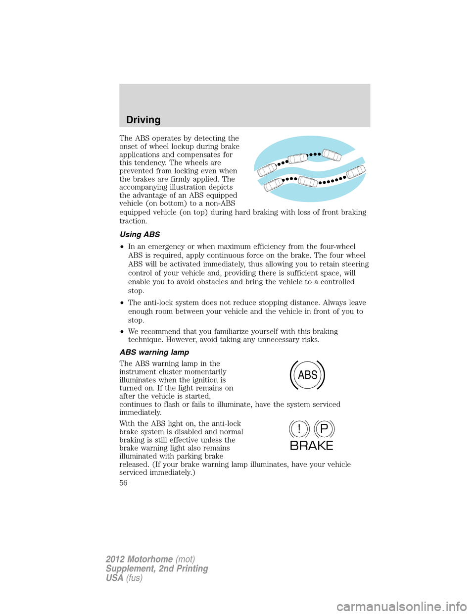
The ABS operates by detecting the
onset of wheel lockup during brake
applications and compensates for
this tendency. The wheels are
prevented from locking even when
the brakes are firmly applied. The
accompanying illustration depicts
the advantage of an ABS equipped
vehicle (on bottom) to a non-ABS
equipped vehicle (on top) during hard braking with loss of front braking
traction.
Using ABS
•In an emergency or when maximum efficiency from the four-wheel
ABS is required, apply continuous force on the brake. The four wheel
ABS will be activated immediately, thus allowing you to retain steering
control of your vehicle and, providing there is sufficient space, will
enable you to avoid obstacles and bring the vehicle to a controlled
stop.
•The anti-lock system does not reduce stopping distance. Always leave
enough room between your vehicle and the vehicle in front of you to
stop.
•We recommend that you familiarize yourself with this braking
technique. However, avoid taking any unnecessary risks.
ABS warning lamp
The ABS warning lamp in the
instrument cluster momentarily
illuminates when the ignition is
turned on. If the light remains on
after the vehicle is started,
continues to flash or fails to illuminate, have the system serviced
immediately.
With the ABS light on, the anti-lock
brake system is disabled and normal
braking is still effective unless the
brake warning light also remains
illuminated with parking brake
released. (If your brake warning lamp illuminates, have your vehicle
serviced immediately.)
ABS
P!
BRAKE
Driving
56
2012 Motorhome(mot)
Supplement, 2nd Printing
USA(fus)
Page 60 of 160
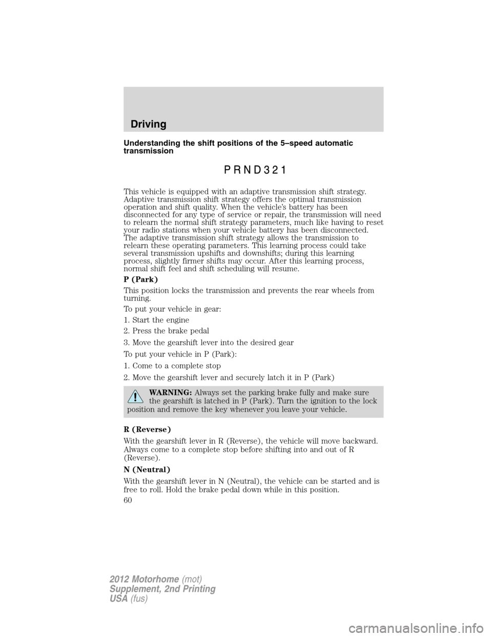
Understanding the shift positions of the 5–speed automatic
transmission
This vehicle is equipped with an adaptive transmission shift strategy.
Adaptive transmission shift strategy offers the optimal transmission
operation and shift quality. When the vehicle’s battery has been
disconnected for any type of service or repair, the transmission will need
to relearn the normal shift strategy parameters, much like having to reset
your radio stations when your vehicle battery has been disconnected.
The adaptive transmission shift strategy allows the transmission to
relearn these operating parameters. This learning process could take
several transmission upshifts and downshifts; during this learning
process, slightly firmer shifts may occur. After this learning process,
normal shift feel and shift scheduling will resume.
P (Park)
This position locks the transmission and prevents the rear wheels from
turning.
To put your vehicle in gear:
1. Start the engine
2. Press the brake pedal
3. Move the gearshift lever into the desired gear
To put your vehicle in P (Park):
1. Come to a complete stop
2. Move the gearshift lever and securely latch it in P (Park)
WARNING:Always set the parking brake fully and make sure
the gearshift is latched in P (Park). Turn the ignition to the lock
position and remove the key whenever you leave your vehicle.
R (Reverse)
With the gearshift lever in R (Reverse), the vehicle will move backward.
Always come to a complete stop before shifting into and out of R
(Reverse).
N (Neutral)
With the gearshift lever in N (Neutral), the vehicle can be started and is
free to roll. Hold the brake pedal down while in this position.
Driving
60
2012 Motorhome(mot)
Supplement, 2nd Printing
USA(fus)