battery location FORD F SERIES MOTORHOME AND COMMERCIAL CHASSIS 2012 12.G Owners Manual
[x] Cancel search | Manufacturer: FORD, Model Year: 2012, Model line: F SERIES MOTORHOME AND COMMERCIAL CHASSIS, Model: FORD F SERIES MOTORHOME AND COMMERCIAL CHASSIS 2012 12.GPages: 160, PDF Size: 1.22 MB
Page 59 of 160
In an emergency, to disable the malfunctioning brake-shift interlock
feature in order to shift the vehicle from P (Park) follow these steps:
WARNING:To prevent vehicle movement when following this
procedure, park on a level surface, ensure parking brake is set,
and block the rear wheels.
1. Apply the parking brake. Turn key to the lock position, and then
remove the key.
2. Disconnect the negative (black) battery cable from the battery.
3. Insert the key and turn to the off position. Shift to N (Neutral).
4. Reconnect the negative (black) battery cable to the battery.
5. Start the vehicle.
See your authorized dealer for service immediately.
WARNING:If your brake lamps are not working properly or if
you have disconnected the vehicle battery cables, the vehicle
brake lamps and hazard flashers may not properly warn traffic of a
vehicle breakdown or approaching danger, which can increase the risk
of serious injury or death. To minimize the risk of serious injury or
death, be aware of your surroundings, use other hazard signaling
devices if available, and move the vehicle to a safe location away from
traffic as soon as possible.
WARNING:Do not drive your vehicle until you verify that the
brake lamps are working.
WARNING:Always set the parking brake fully and make sure
the gearshift is latched in P (Park). Turn the ignition to the lock
position and remove the key whenever you leave your vehicle.
WARNING:If the parking brake is fully released, but the brake
warning lamp remains illuminated, the brakes may not be
working properly. See your authorized dealer.
Driving
59
2012 Motorhome(mot)
Supplement, 2nd Printing
USA(fus)
Page 64 of 160
ROADSIDE ASSISTANCE
Vehicles sold in the U.S. : Getting roadside assistance
To fully assist you should you have a vehicle concern, Ford Motor
Company offers a complimentary roadside assistance program. This
program is separate from the New Vehicle Limited Warranty. The service
is available:
•24–hours, seven days a week
•for the coverage period listed on the Roadside Assistance Card
included in your Owner Guide portfolio.
Roadside assistance will cover:
•a flat tire change with a good spare, if provided with the vehicle
(except vehicles that have been supplied with a tire inflation kit)
•battery jump start
•lock-out assistance (key replacement cost is the customer’s
responsibility)
•fuel delivery – Independent Service Contractors, if not prohibited by
state, local or municipal law shall deliver 5 gallons (18.9L) of fuel to a
disabled vehicle. Fuel delivery service is limited to two no-charge
occurrences within a 12-month period.
•towing – Ford and Lincoln eligible vehicle towed to an authorized
dealer within 35 miles (56.3 km) of the disablement location or to the
nearest authorized dealer. If a member requests to be towed to an
authorized dealer more than 35 miles (56.3 km) from the disablement
location, the member shall be responsible for any mileage costs in
excess of 35 miles (56.3 km).
Trailers shall be covered up to $200 if the disabled eligible vehicle
requires service at the nearest authorized dealer. If the trailer is disabled,
but the towing vehicle is operational, the trailer does not qualify for any
roadside services.
Vehicles sold in the U.S. : Using roadside assistance
Customers who require roadside assistance, may contact 1-800-444-3311.
Vehicles sold in Canada : Getting roadside assistance
Canadian customers who require roadside assistance, call
1–800–665–2006.
Roadside Emergencies
64
2012 Motorhome(mot)
Supplement, 2nd Printing
USA(fus)
Page 68 of 160
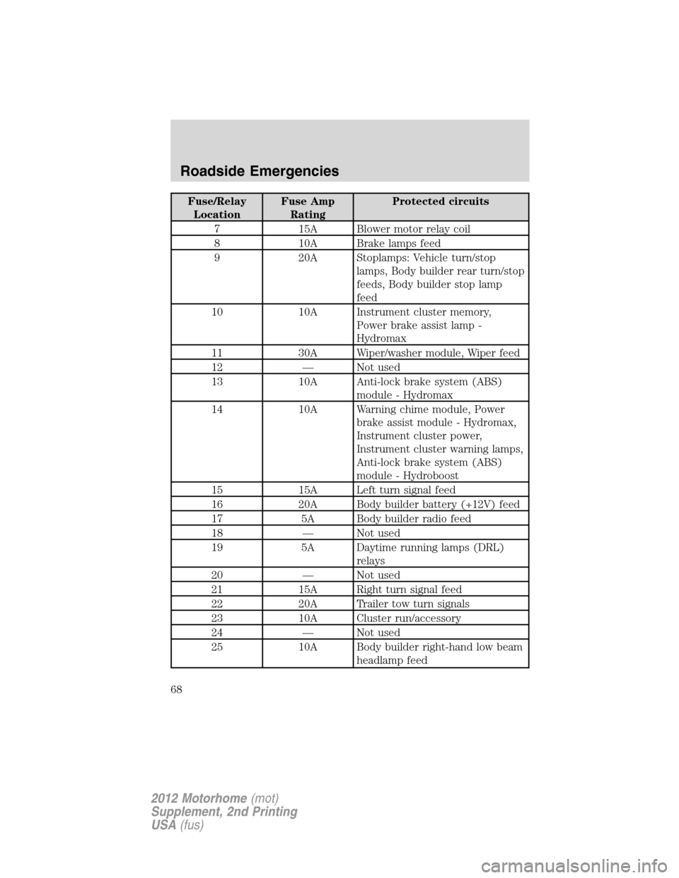
Fuse/Relay
LocationFuse Amp
RatingProtected circuits
7 15A Blower motor relay coil
8 10A Brake lamps feed
9 20A Stoplamps: Vehicle turn/stop
lamps, Body builder rear turn/stop
feeds, Body builder stop lamp
feed
10 10A Instrument cluster memory,
Power brake assist lamp -
Hydromax
11 30A Wiper/washer module, Wiper feed
12 — Not used
13 10A Anti-lock brake system (ABS)
module - Hydromax
14 10A Warning chime module, Power
brake assist module - Hydromax,
Instrument cluster power,
Instrument cluster warning lamps,
Anti-lock brake system (ABS)
module - Hydroboost
15 15A Left turn signal feed
16 20A Body builder battery (+12V) feed
17 5A Body builder radio feed
18 — Not used
19 5A Daytime running lamps (DRL)
relays
20 — Not used
21 15A Right turn signal feed
22 20A Trailer tow turn signals
23 10A Cluster run/accessory
24 — Not used
25 10A Body builder right-hand low beam
headlamp feed
Roadside Emergencies
68
2012 Motorhome(mot)
Supplement, 2nd Printing
USA(fus)
Page 70 of 160
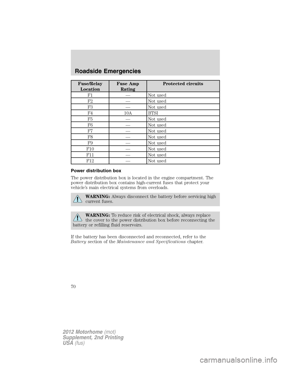
Fuse/Relay
LocationFuse Amp
RatingProtected circuits
F1 — Not used
F2 — Not used
F3 — Not used
F4 10A BTSI
F5 — Not used
F6 — Not used
F7 — Not used
F8 — Not used
F9 — Not used
F10 — Not used
F11 — Not used
F12 — Not used
Power distribution box
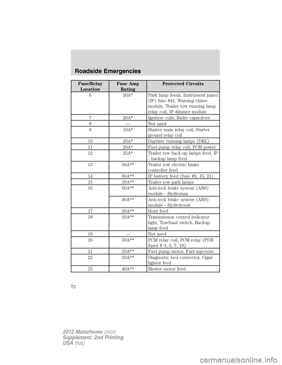
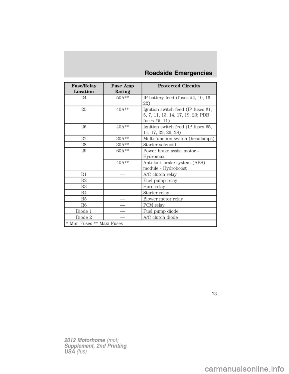
The power distribution box is located in the engine compartment. The
power distribution box contains high-current fuses that protect your
vehicle’s main electrical systems from overloads.
WARNING:Always disconnect the battery before servicing high
current fuses.
WARNING:To reduce risk of electrical shock, always replace
the cover to the power distribution box before reconnecting the
battery or refilling fluid reservoirs.
If the battery has been disconnected and reconnected, refer to the
Batterysection of theMaintenance and Specificationschapter.
Roadside Emergencies
70
2012 Motorhome(mot)
Supplement, 2nd Printing
USA(fus)
Page 72 of 160
Fuse/Relay
LocationFuse Amp
RatingProtected Circuits
6 20A* Park lamp feeds, Instrument panel
(IP) fuse #41, Warning chime
module, Trailer tow running lamp
relay coil, IP dimmer module
7 20A* Ignition coils, Radio capacitors
8 — Not used
9 10A* Starter main relay coil, Starter
ground relay coil
10 20A* Daytime running lamps (DRL)
11 20A* Fuel pump relay coil, PCM power
12 25A* Trailer tow back-up lamps feed, IP
- backup lamp feed
13 30A** Trailer tow electric brake
controller feed
14 60A** IP battery feed (fuse #9, 15, 21)
15 20A** Trailer tow park lamps
16 60A** Anti-lock brake system (ABS)
module - Hydromax
40A** Anti-lock brake system (ABS)
module - Hydroboost
17 20A** Horn feed
18 20A** Transmission control indicator
light, Tow/haul switch, Backup
lamp feed
19 — Not used
20 30A** PCM relay coil, PCM relay (PDB
fuses#3,5,7,18)
21 20A** Fuel pump motor, Fuel injectors
22 20A** Diagnostic tool connector, Cigar
lighter feed
23 40A** Blower motor feed
Roadside Emergencies
72
2012 Motorhome(mot)
Supplement, 2nd Printing
USA(fus)
Page 73 of 160
Fuse/Relay
LocationFuse Amp
RatingProtected Circuits
24 50A** IP battery feed (fuses #4, 10, 16,
22)
25 40A** Ignition switch feed (IP fuses #1,
5, 7, 11, 13, 14, 17, 19, 23; PDB
fuses #9, 11)
26 40A** Ignition switch feed (IP fuses #5,
11, 17, 23, 26, 38)
27 30A** Multi-function switch (headlamps)
28 30A** Starter solenoid
29 60A** Power brake assist motor -
Hydromax
40A** Anti-lock brake system (ABS)
module - Hydroboost
R1 — A/C clutch relay
R2 — Fuel pump relay
R3 — Horn relay
R4 — Starter relay
R5 — Blower motor relay
R6 — PCM relay
Diode 1 — Fuel pump diode
Diode 2 — A/C clutch diode
* Mini Fuses ** Maxi Fuses
Roadside Emergencies
73
2012 Motorhome(mot)
Supplement, 2nd Printing
USA(fus)