FORD F150 2008 11.G Owners Manual
Manufacturer: FORD, Model Year: 2008, Model line: F150, Model: FORD F150 2008 11.GPages: 400, PDF Size: 3.94 MB
Page 131 of 400
The message center will display the last selected feature if there are no
more warning messages. This allows you to use the full functionality of
the message center after you acknowledge the warning by pressing the
RESET control and clearing the warning message.
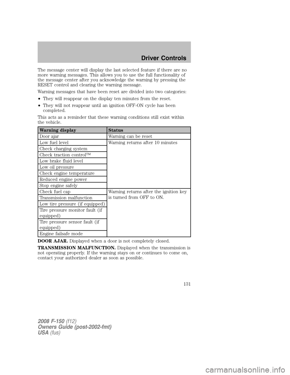
Warning messages that have been reset are divided into two categories:
•They will reappear on the display ten minutes from the reset.
•They will not reappear until an ignition OFF-ON cycle has been
completed.
This acts as a reminder that these warning conditions still exist within
the vehicle.
Warning display Status
Door ajar Warning can be reset
Low fuel level Warning returns after 10 minutes
Check charging system
Check traction control™
Low brake fluid level
Low oil pressure
Check engine temperature
Reduced engine power
Stop engine safely
Check fuel cap Warning returns after the ignition key
is turned from OFF to ON.
Transmission malfunction
Low tire pressure (if equipped)
Tire pressure monitor fault (if
equipped)
Tire pressure sensor fault (if
equipped)
Engine failsafe mode
DOOR AJAR.Displayed when a door is not completely closed.
TRANSMISSION MALFUNCTION.Displayed when the transmission is
not operating properly. If the warning stays on or continues to come on,
contact your authorized dealer as soon as possible.
2008 F-150(f12)
Owners Guide (post-2002-fmt)
USA(fus)
Driver Controls
131
Page 132 of 400
CHECK ENGINE TEMPERATURE.Displayed when the engine
coolant is overheating. Stop the vehicle as soon as safely possible, turn
off the engine and let it cool. Check the coolant and coolant level. Refer
toEngine coolantin theMaintenance and Specificationschapter. If
the warning stays on or continues to come on, contact your authorized
dealer as soon as possible.
Never remove the coolant reservoir cap while the engine is
running or hot.
REDUCED ENGINE POWER.Displayed when the engine is
overheating. Stop the vehicle as soon as safely possible, turn off the
engine. If the warning stays on or continues to come on, contact your
authorized dealer as soon as possible.
STOP ENGINE SAFELY.Displayed when the engine is overheating.
Stop the vehicle as soon as safely possible, turn off the engine. If the
warning stays on or continues to come on, contact your authorized
dealer as soon as possible.
LOW FUEL LEVEL.Displayed as an early reminder of a low fuel
condition.
CHECK CHARGING SYSTEM.Displayed when the electrical system is
not maintaining proper voltage. If you are operating electrical accessories
when the engine is idling at a low speed, turn off as many of the
electrical loads as soon as possible. If the warning stays on or comes on
when the engine is operating at normal speeds, have the electrical
system checked as soon as possible.
CHECK TRACTION CONTROL™.Displayed when the Traction
Control™ system is not operating properly. If this message is displayed
on the message center the Traction Control™ system will be partially
operable. If this warning stays on, contact your authorized dealer for
service as soon as possible. For further information, refer toTraction
control™in theDrivingchapter.
LOW BRAKE FLUID LEVEL.Indicates the brake fluid level is low and
the brake system should be inspected immediately. Refer toBrake fluid
reservoirin theMaintenance and Specificationschapter.
LOW OIL PRESSURE.Displayed when the engine oil pressure is low. If
this warning message is displayed, check the level of the engine oil.
Refer toEngine oilin theMaintenance and Specificationschapter for
information about adding engine oil. If the oil level is OK and this
warning persists, shut down the engine immediately and contact your
authorized dealer for service.
2008 F-150(f12)
Owners Guide (post-2002-fmt)
USA(fus)
Driver Controls
132
Page 133 of 400

CHECK FUEL CAP.Displayed when the fuel filler cap is not properly
installed. Check the fuel filler cap for proper installation. Refer toFuel
filler capunder theFuel information sectionin theMaintenance and
Specificationschapter.
LOW TIRE PRESSURE (if equipped).Displayed when one or more
tires on your vehicle have low tire pressure. Refer toInflating Your
Tiresin theTires, Wheels and Loadingchapter.
TIRE PRESSURE MONITOR FAULT (if equipped).Displayed when
the Tire Pressure Monitoring System is malfunctioning. If the warning
stays on or continues to come on, have the system inspected by your
authorized dealer.
TIRE PRESSURE SENSOR FAULT (if equipped).Displayed when a
tire pressure sensor is malfunctioning, or your spare tire is in use. For
more information on how the system operates under these conditions,
refer toUnderstanding Your Tire Pressure Monitoring Systemin the
Tires, Wheels and Loadingchapter. If the warning stays on or
continues to come on, have the system inspected by your authorized
dealer.
ENGINE FAILSAFE MODE.Displayed when the engine has defaulted
to a ’limp-home’ operation. If the warning stays on or continues to come
on, contact your authorized dealer as soon as possible.
DATA ERR.These messages indicate improper operation of the vehicle
network communication between electronic modules.
•Fuel computer
•Charging system
•Autolamp delay
•Auto locks
•Brake fluid
•Compass
•Outside temperature
•Engine sensor
Contact your authorized dealer as soon as possible if these messages
occur on a regular basis.
2008 F-150(f12)
Owners Guide (post-2002-fmt)
USA(fus)
Driver Controls
133
Page 134 of 400
POSITIVE RETENTION FLOOR MAT
Do not install additional floor mats on top of the factory installed
floor mats as they may interfere with the accelerator or the
brake pedals.
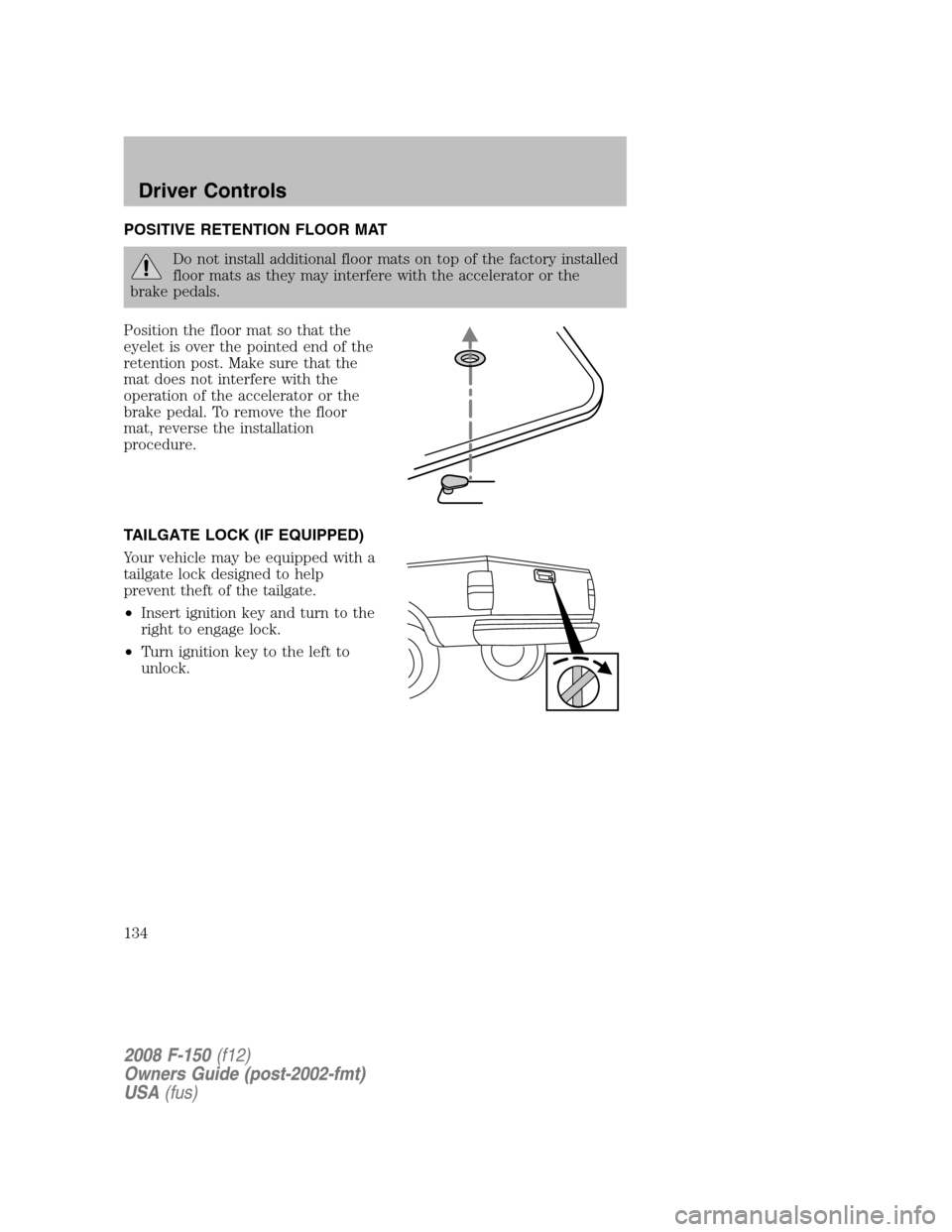
Position the floor mat so that the
eyelet is over the pointed end of the
retention post. Make sure that the
mat does not interfere with the
operation of the accelerator or the
brake pedal. To remove the floor
mat, reverse the installation
procedure.
TAILGATE LOCK (IF EQUIPPED)
Your vehicle may be equipped with a
tailgate lock designed to help
prevent theft of the tailgate.
•Insert ignition key and turn to the
right to engage lock.
•Turn ignition key to the left to
unlock.
2008 F-150(f12)
Owners Guide (post-2002-fmt)
USA(fus)
Driver Controls
134
Page 135 of 400
Tailgate removal
Your tailgate is removable to allow more room for loading.
Note:If equipped with a Reverse Camera System (RCS), do steps 1
through 3 before removing the tailgate.
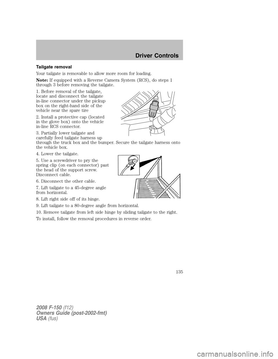
1. Before removal of the tailgate,
locate and disconnect the tailgate
in-line connector under the pickup
box on the right-hand side of the
vehicle near the spare tire
2. Install a protective cap (located
in the glove box) onto the vehicle
in-line RCS connector.
3. Partially lower tailgate and
carefully feed tailgate harness up
through the truck box and the bumper. Secure the tailgate harness onto
the vehicle box.
4. Lower the tailgate.
5. Use a screwdriver to pry the
spring clip (on each connector) past
the head of the support screw.
Disconnect cable.
6. Disconnect the other cable.
7. Lift tailgate to a 45-degree angle
from horizontal.
8. Lift right side off of its hinge.
9. Lift tailgate to a 80-degree angle from horizontal.
10. Remove tailgate from left side hinge by sliding tailgate to the right.
To install, follow the removal procedures in reverse order.
2008 F-150(f12)
Owners Guide (post-2002-fmt)
USA(fus)
Driver Controls
135
Page 136 of 400
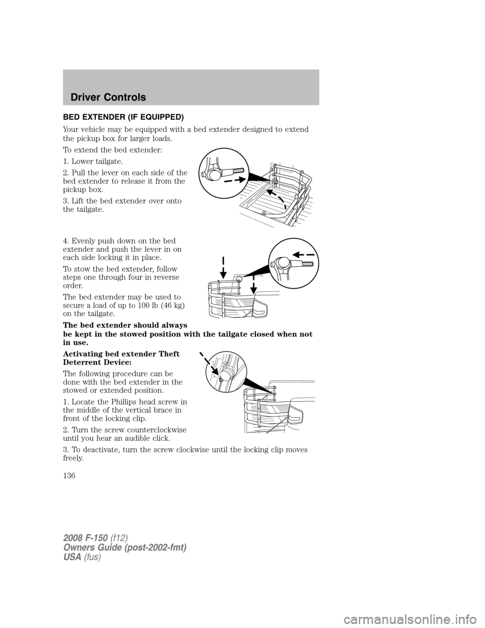
BED EXTENDER (IF EQUIPPED)
Your vehicle may be equipped with a bed extender designed to extend
the pickup box for larger loads.
To extend the bed extender:
1. Lower tailgate.
2. Pull the lever on each side of the
bed extender to release it from the
pickup box.
3. Lift the bed extender over onto
the tailgate.
4. Evenly push down on the bed
extender and push the lever in on
each side locking it in place.
To stow the bed extender, follow
steps one through four in reverse
order.
The bed extender may be used to
secure a load of up to 100 lb (46 kg)
on the tailgate.
The bed extender should always
be kept in the stowed position with the tailgate closed when not
in use.
Activating bed extender Theft
Deterrent Device:
The following procedure can be
done with the bed extender in the
stowed or extended position.
1. Locate the Phillips head screw in
the middle of the vertical brace in
front of the locking clip.
2. Turn the screw counterclockwise
until you hear an audible click.
3. To deactivate, turn the screw clockwise until the locking clip moves
freely.
2008 F-150(f12)
Owners Guide (post-2002-fmt)
USA(fus)
Driver Controls
136
Page 137 of 400
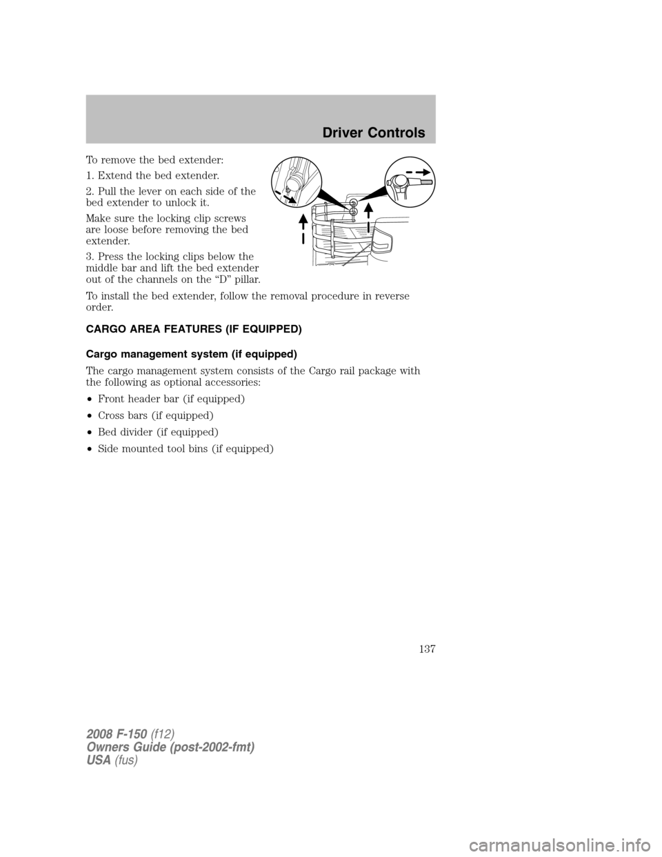
To remove the bed extender:
1. Extend the bed extender.
2. Pull the lever on each side of the
bed extender to unlock it.
Make sure the locking clip screws
are loose before removing the bed
extender.
3. Press the locking clips below the
middle bar and lift the bed extender
out of the channels on the “D” pillar.
To install the bed extender, follow the removal procedure in reverse
order.
CARGO AREA FEATURES (IF EQUIPPED)
Cargo management system (if equipped)
The cargo management system consists of the Cargo rail package with
the following as optional accessories:
•Front header bar (if equipped)
•Cross bars (if equipped)
•Bed divider (if equipped)
•Side mounted tool bins (if equipped)
2008 F-150(f12)
Owners Guide (post-2002-fmt)
USA(fus)
Driver Controls
137
Page 138 of 400
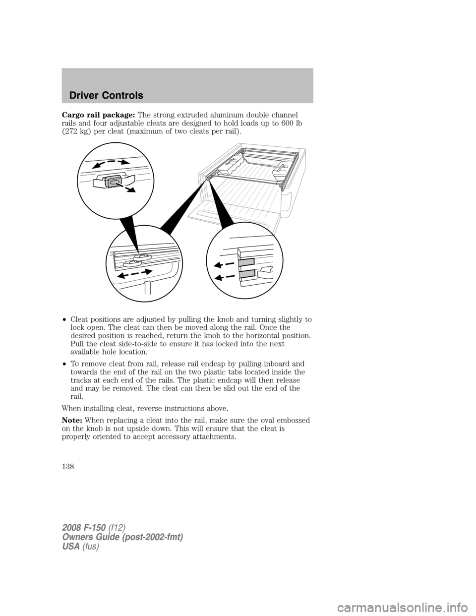
Cargo rail package:The strong extruded aluminum double channel
rails and four adjustable cleats are designed to hold loads up to 600 lb
(272 kg) per cleat (maximum of two cleats per rail).
•Cleat positions are adjusted by pulling the knob and turning slightly to
lock open. The cleat can then be moved along the rail. Once the
desired position is reached, return the knob to the horizontal position.
Pull the cleat side-to-side to ensure it has locked into the next
available hole location.
•To remove cleat from rail, release rail endcap by pulling inboard and
towards the end of the rail on the two plastic tabs located inside the
tracks at each end of the rails. The plastic endcap will then release
and may be removed. The cleat can then be slid out the end of the
rail.
When installing cleat, reverse instructions above.
Note:When replacing a cleat into the rail, make sure the oval embossed
on the knob is not upside down. This will ensure that the cleat is
properly oriented to accept accessory attachments.
2008 F-150(f12)
Owners Guide (post-2002-fmt)
USA(fus)
Driver Controls
138
Page 139 of 400
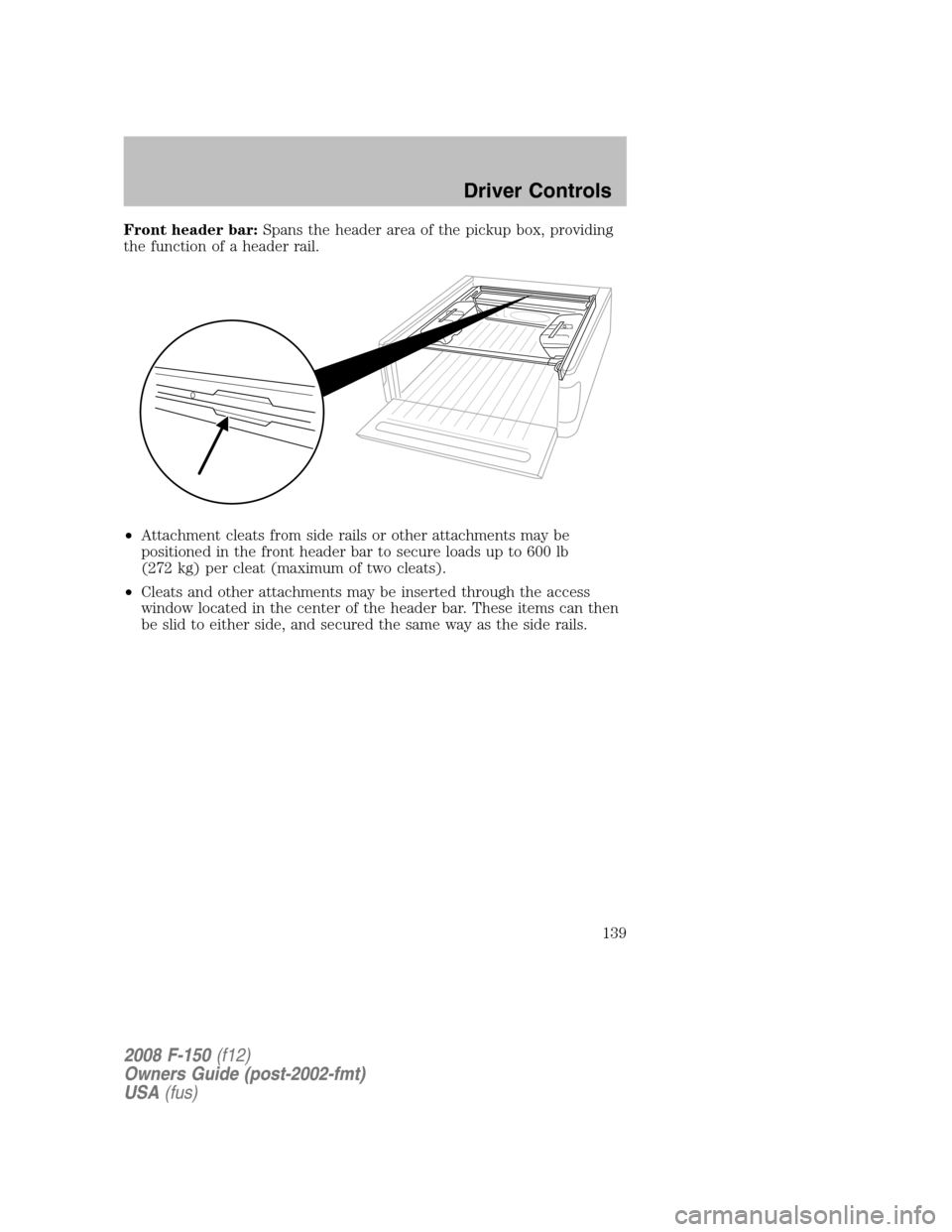
Front header bar:Spans the header area of the pickup box, providing
the function of a header rail.
•Attachment cleats from side rails or other attachments may be
positioned in the front header bar to secure loads up to 600 lb
(272 kg) per cleat (maximum of two cleats).
•Cleats and other attachments may be inserted through the access
window located in the center of the header bar. These items can then
be slid to either side, and secured the same way as the side rails.
2008 F-150(f12)
Owners Guide (post-2002-fmt)
USA(fus)
Driver Controls
139
Page 140 of 400
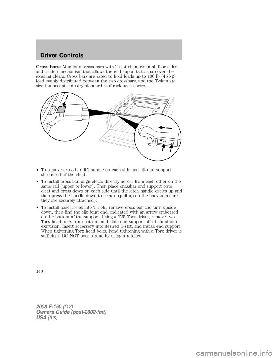
Cross bars:Aluminum cross bars with T-slot channels in all four sides,
and a latch mechanism that allows the end supports to snap over the
existing cleats. Cross bars are rated to hold loads up to 100 lb (45 kg)
load evenly distributed between the two crossbars, and the T-slots are
sized to accept industry-standard roof rack accessories.
•To remove cross bar, lift handle on each side and lift end support
shroud off of the cleat.
•To install cross bar, align cleats directly across from each other on the
same rail (upper or lower). Then place crossbar end support onto
cleat and press down on each side until the latch handle cycles up and
then press the handle down to secure (pull up on the bars to ensure
they are securely attached).
•To install accessories into T-slots, remove cross bar and turn upside
down, then find the slip joint end, indicated with an arrow embossed
on the bottom of the support. Using a T25 Torx driver, remove two
Torx head bolts from bottom, and slide end support off of aluminum
extrusion. Insert accessory into desired T-slot, and install end support.
When tightening Torx head bolts, hand tightening with a Torx driver is
sufficient, DO NOT over torque by using a ratchet.
2008 F-150(f12)
Owners Guide (post-2002-fmt)
USA(fus)
Driver Controls
140