battery FORD F150 2008 11.G Owner's Manual
[x] Cancel search | Manufacturer: FORD, Model Year: 2008, Model line: F150, Model: FORD F150 2008 11.GPages: 400, PDF Size: 3.94 MB
Page 303 of 400
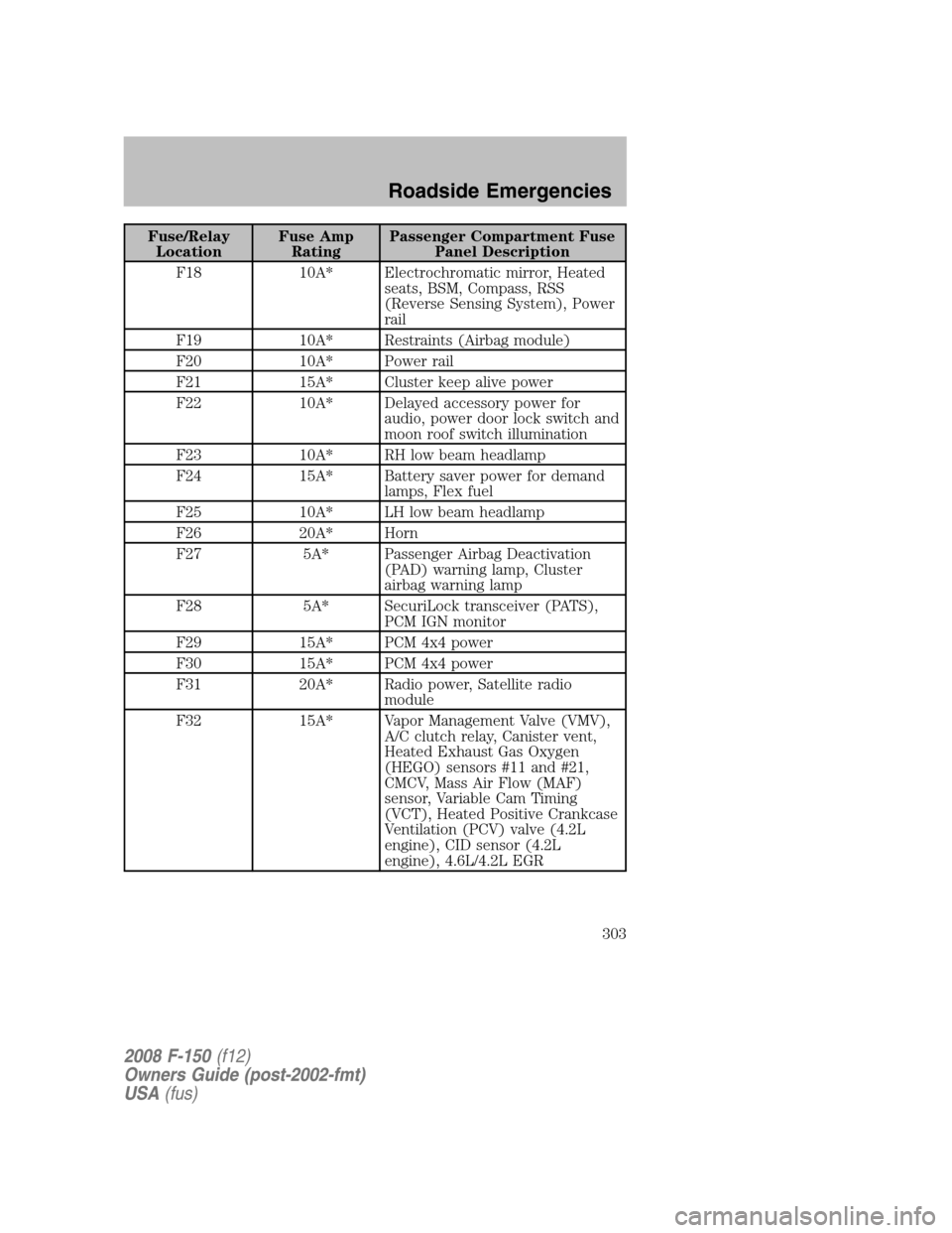
Fuse/Relay
LocationFuse Amp
RatingPassenger Compartment Fuse
Panel Description
F18 10A* Electrochromatic mirror, Heated
seats, BSM, Compass, RSS
(Reverse Sensing System), Power
rail
F19 10A* Restraints (Airbag module)
F20 10A* Power rail
F21 15A* Cluster keep alive power
F22 10A* Delayed accessory power for
audio, power door lock switch and
moon roof switch illumination
F23 10A* RH low beam headlamp
F24 15A* Battery saver power for demand
lamps, Flex fuel
F25 10A* LH low beam headlamp
F26 20A* Horn
F27 5A* Passenger Airbag Deactivation
(PAD) warning lamp, Cluster
airbag warning lamp
F28 5A* SecuriLock transceiver (PATS),
PCM IGN monitor
F29 15A* PCM 4x4 power
F30 15A* PCM 4x4 power
F31 20A* Radio power, Satellite radio
module
F32 15A* Vapor Management Valve (VMV),
A/C clutch relay, Canister vent,
Heated Exhaust Gas Oxygen
(HEGO) sensors #11 and #21,
CMCV, Mass Air Flow (MAF)
sensor, Variable Cam Timing
(VCT), Heated Positive Crankcase
Ventilation (PCV) valve (4.2L
engine), CID sensor (4.2L
engine), 4.6L/4.2L EGR
2008 F-150(f12)
Owners Guide (post-2002-fmt)
USA(fus)
Roadside Emergencies
303
Page 304 of 400
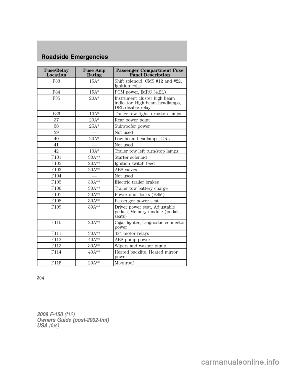
Fuse/Relay
LocationFuse Amp
RatingPassenger Compartment Fuse
Panel Description
F33 15A* Shift solenoid, CMS #12 and #22,
Ignition coils
F34 15A* PCM power, IMRC (4.2L)
F35 20A* Instrument cluster high beam
indicator, High beam headlamps,
DRL disable relay
F36 10A* Trailer tow right turn/stop lamps
37 20A* Rear power point
38 25A* Subwoofer power
39 — Not used
40 20A* Low beam headlamps, DRL
41 — Not used
42 10A* Trailer tow left turn/stop lamps
F101 30A** Starter solenoid
F102 20A** Ignition switch feed
F103 20A** ABS valves
F104 — Not used
F105 30A** Electric trailer brakes
F106 30A** Trailer tow battery charge
F107 30A** Power door locks (BSM)
F108 30A** Passenger power seat
F109 30A** Driver power seat, Adjustable
pedals, Memory module (pedals,
seats)
F110 20A** Cigar lighter, Diagnostic connector
power
F111 30A** 4x4 motor relays
F112 40A** ABS pump power
F113 30A** Wipers and washer pump
F114 40A** Heated backlite, Heated mirror
power
F115 20A** Moonroof
2008 F-150(f12)
Owners Guide (post-2002-fmt)
USA(fus)
Roadside Emergencies
304
Page 305 of 400
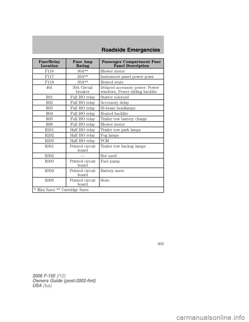
Fuse/Relay
LocationFuse Amp
RatingPassenger Compartment Fuse
Panel Description
F116 30A** Blower motor
F117 20A** Instrument panel power point
F118 30A** Heated seats
401 30A Circuit
breakerDelayed accessory power: Power
windows, Power sliding backlite
R01 Full ISO relay Starter solenoid
R02 Full ISO relay Accessory delay
R03 Full ISO relay Hi-beam headlamps
R04 Full ISO relay Heated backlite
R05 Full ISO relay Trailer tow battery charge
R06 Full ISO relay Blower motor
R201 Half ISO relay Trailer tow park lamps
R202 Half ISO relay Fog lamps
R203 Half ISO relay PCM
R301 Printed circuit
boardTrailer tow backup lamps
R302 — Not used
R303 Printed circuit
boardFuel pump
R304 Printed circuit
boardBattery saver
R305 Printed circuit
boardHorn
* Mini fuses ** Cartridge fuses
2008 F-150(f12)
Owners Guide (post-2002-fmt)
USA(fus)
Roadside Emergencies
305
Page 315 of 400
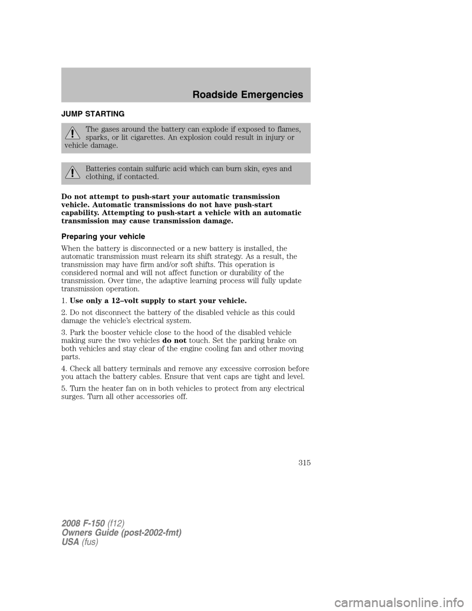
JUMP STARTING
The gases around the battery can explode if exposed to flames,
sparks, or lit cigarettes. An explosion could result in injury or
vehicle damage.
Batteries contain sulfuric acid which can burn skin, eyes and
clothing, if contacted.
Do not attempt to push-start your automatic transmission
vehicle. Automatic transmissions do not have push-start
capability. Attempting to push-start a vehicle with an automatic
transmission may cause transmission damage.
Preparing your vehicle
When the battery is disconnected or a new battery is installed, the
automatic transmission must relearn its shift strategy. As a result, the
transmission may have firm and/or soft shifts. This operation is
considered normal and will not affect function or durability of the
transmission. Over time, the adaptive learning process will fully update
transmission operation.
1.Use only a 12–volt supply to start your vehicle.
2. Do not disconnect the battery of the disabled vehicle as this could
damage the vehicle’s electrical system.
3. Park the booster vehicle close to the hood of the disabled vehicle
making sure the two vehiclesdo nottouch. Set the parking brake on
both vehicles and stay clear of the engine cooling fan and other moving
parts.
4. Check all battery terminals and remove any excessive corrosion before
you attach the battery cables. Ensure that vent caps are tight and level.
5. Turn the heater fan on in both vehicles to protect from any electrical
surges. Turn all other accessories off.
2008 F-150(f12)
Owners Guide (post-2002-fmt)
USA(fus)
Roadside Emergencies
315
Page 316 of 400
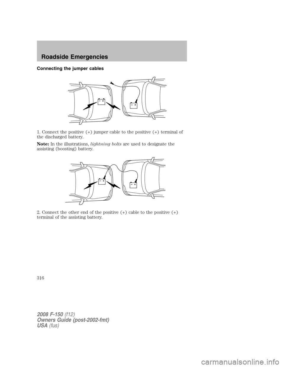
Connecting the jumper cables
1. Connect the positive (+) jumper cable to the positive (+) terminal of
the discharged battery.
Note:In the illustrations,lightning boltsare used to designate the
assisting (boosting) battery.
2. Connect the other end of the positive (+) cable to the positive (+)
terminal of the assisting battery.
+–+–
+–+–
2008 F-150(f12)
Owners Guide (post-2002-fmt)
USA(fus)
Roadside Emergencies
316
Page 317 of 400
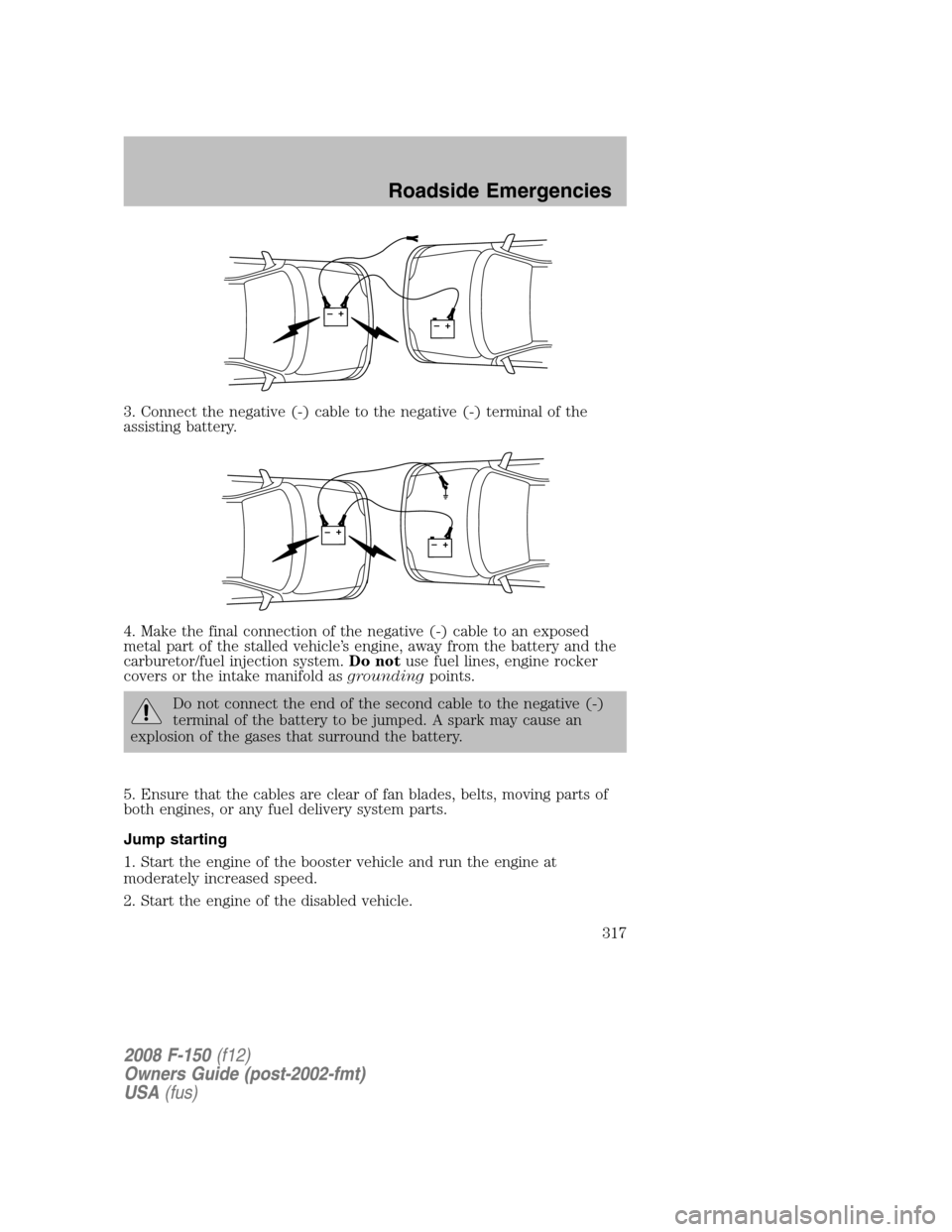
3. Connect the negative (-) cable to the negative (-) terminal of the
assisting battery.
4. Make the final connection of the negative (-) cable to an exposed
metal part of the stalled vehicle’s engine, away from the battery and the
carburetor/fuel injection system.Do notuse fuel lines, engine rocker
covers or the intake manifold asgroundingpoints.
Do not connect the end of the second cable to the negative (-)
terminal of the battery to be jumped. A spark may cause an
explosion of the gases that surround the battery.
5. Ensure that the cables are clear of fan blades, belts, moving parts of
both engines, or any fuel delivery system parts.
Jump starting
1. Start the engine of the booster vehicle and run the engine at
moderately increased speed.
2. Start the engine of the disabled vehicle.
+–+–
+–+–
2008 F-150(f12)
Owners Guide (post-2002-fmt)
USA(fus)
Roadside Emergencies
317
Page 318 of 400
3. Once the disabled vehicle has been started, run both engines for an
additional three minutes before disconnecting the jumper cables.
Removing the jumper cables
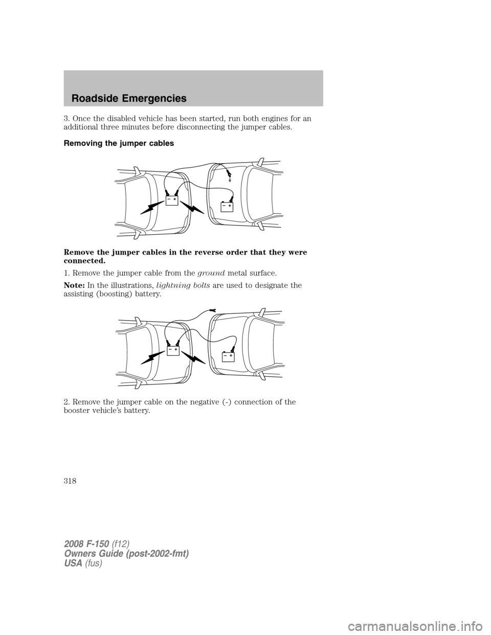
Remove the jumper cables in the reverse order that they were
connected.
1. Remove the jumper cable from thegroundmetal surface.
Note:In the illustrations,lightning boltsare used to designate the
assisting (boosting) battery.
2. Remove the jumper cable on the negative (-) connection of the
booster vehicle’s battery.
+–+–
+–+–
2008 F-150(f12)
Owners Guide (post-2002-fmt)
USA(fus)
Roadside Emergencies
318
Page 319 of 400
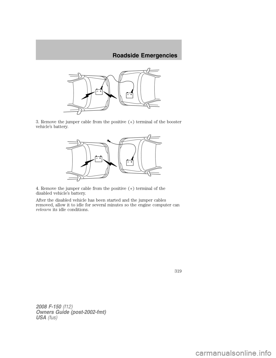
3. Remove the jumper cable from the positive (+) terminal of the booster
vehicle’s battery.
4. Remove the jumper cable from the positive (+) terminal of the
disabled vehicle’s battery.
After the disabled vehicle has been started and the jumper cables
removed, allow it to idle for several minutes so the engine computer can
relearnits idle conditions.
+–+–
+–+–
2008 F-150(f12)
Owners Guide (post-2002-fmt)
USA(fus)
Roadside Emergencies
319
Page 339 of 400
SERVICE RECOMMENDATIONS
To help you service your vehicle, we providescheduled maintenance
informationwhich makes tracking routine service easy.
If your vehicle requires professional service, your authorized dealer can
provide the necessary parts and service. Check yourWarranty Guideto
find out which parts and services are covered.
Use only recommended fuels, lubricants, fluids and service parts
conforming to specifications. Motorcraft parts are designed and built to
provide the best performance in your vehicle.
PRECAUTIONS WHEN SERVICING YOUR VEHICLE
•Do not work on a hot engine.
•Make sure that nothing gets caught in moving parts.
•Do not work on a vehicle with the engine running in an enclosed
space, unless you are sure you have enough ventilation.
•Keep all open flames and other burning (cigarettes) material away
from the battery and all fuel related parts.
Working with the engine off
•Automatic transmission/transaxle:
1. Set the parking brake and shift to P (Park).
2. Turn off the engine and remove the key.
3. Block the wheels.
•Manual transmission/transaxle:
1. Set the parking brake, depress the clutch and place the gearshift in
1 (First).
2. Turn off the engine and remove the key.
3. Block the wheels.
Working with the engine on
•Automatic transmission:
1. Set the parking brake and shift to P (Park).
2. Block the wheels.
•Manual transmission:
1. Set the parking brake, depress the clutch and place the gearshift in
N (Neutral).
2008 F-150(f12)
Owners Guide (post-2002-fmt)
USA(fus)
Maintenance and Specifications
339
Page 341 of 400
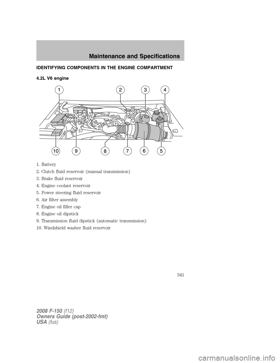
IDENTIFYING COMPONENTS IN THE ENGINE COMPARTMENT
4.2L V6 engine
1. Battery
2. Clutch fluid reservoir (manual transmission)
3. Brake fluid reservoir
4. Engine coolant reservoir
5. Power steering fluid reservoir
6. Air filter assembly
7. Engine oil filler cap
8. Engine oil dipstick
9. Transmission fluid dipstick (automatic transmission)
10. Windshield washer fluid reservoir
2008 F-150(f12)
Owners Guide (post-2002-fmt)
USA(fus)
Maintenance and Specifications
341