FORD F150 2009 12.G Repair Manual
Manufacturer: FORD, Model Year: 2009, Model line: F150, Model: FORD F150 2009 12.GPages: 405, PDF Size: 2.82 MB
Page 61 of 405
Replacing exterior bulbs
Check the operation of all the bulbs frequently.
Replacing headlamp bulbs
1. Make sure that the headlamp control is in the off position and open
the hood.
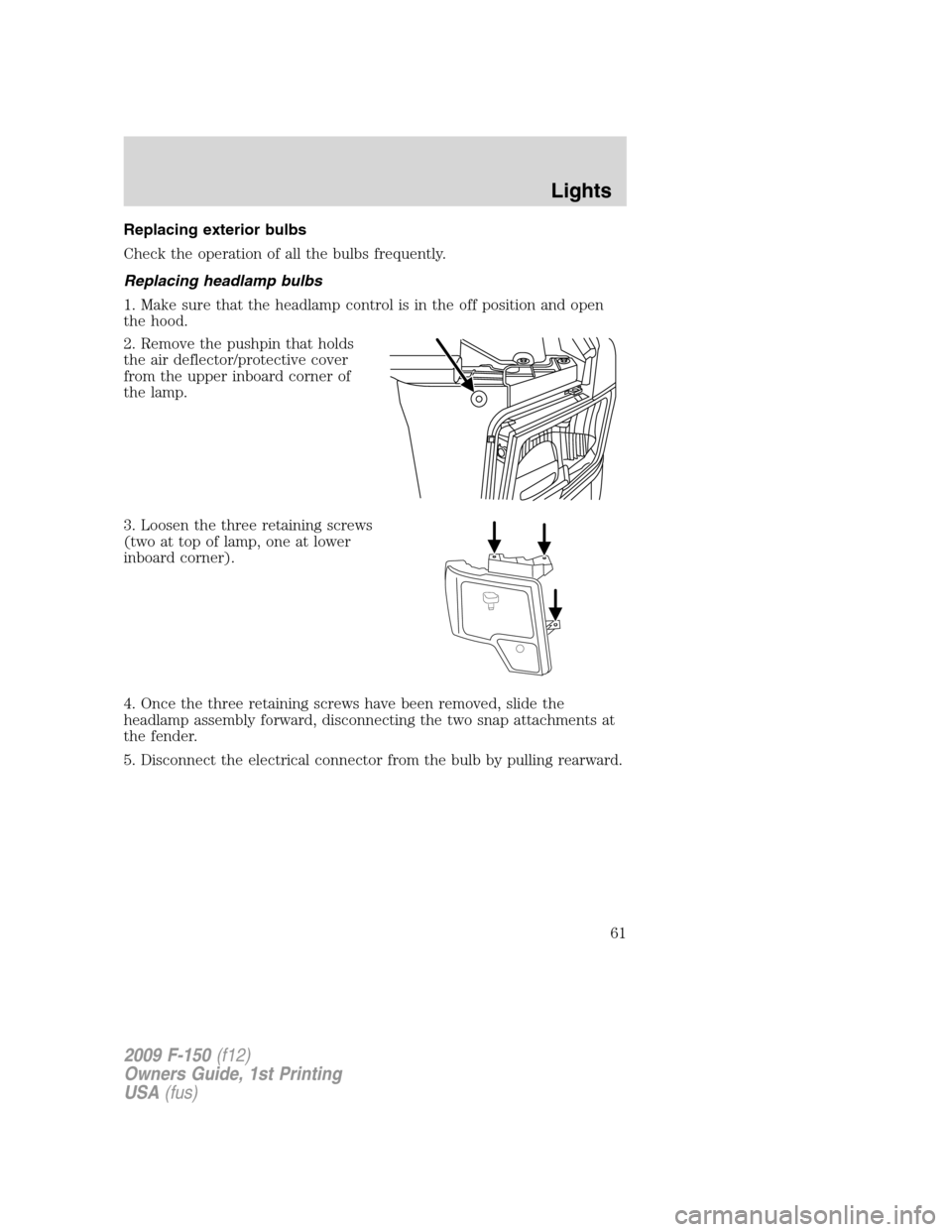
2. Remove the pushpin that holds
the air deflector/protective cover
from the upper inboard corner of
the lamp.
3. Loosen the three retaining screws
(two at top of lamp, one at lower
inboard corner).
4. Once the three retaining screws have been removed, slide the
headlamp assembly forward, disconnecting the two snap attachments at
the fender.
5. Disconnect the electrical connector from the bulb by pulling rearward.
2009 F-150(f12)
Owners Guide, 1st Printing
USA(fus)
Lights
61
Page 62 of 405
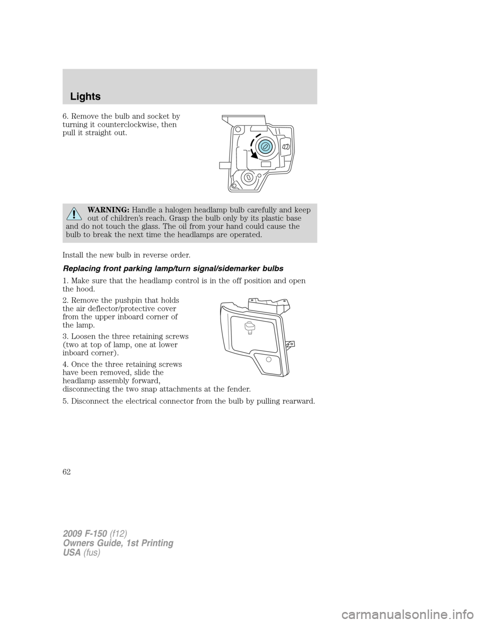
6. Remove the bulb and socket by
turning it counterclockwise, then
pull it straight out.
WARNING:Handle a halogen headlamp bulb carefully and keep
out of children’s reach. Grasp the bulb only by its plastic base
and do not touch the glass. The oil from your hand could cause the
bulb to break the next time the headlamps are operated.
Install the new bulb in reverse order.
Replacing front parking lamp/turn signal/sidemarker bulbs
1. Make sure that the headlamp control is in the off position and open
the hood.
2. Remove the pushpin that holds
the air deflector/protective cover
from the upper inboard corner of
the lamp.
3. Loosen the three retaining screws
(two at top of lamp, one at lower
inboard corner).
4. Once the three retaining screws
have been removed, slide the
headlamp assembly forward,
disconnecting the two snap attachments at the fender.
5. Disconnect the electrical connector from the bulb by pulling rearward.
2009 F-150(f12)
Owners Guide, 1st Printing
USA(fus)
Lights
62
Page 63 of 405
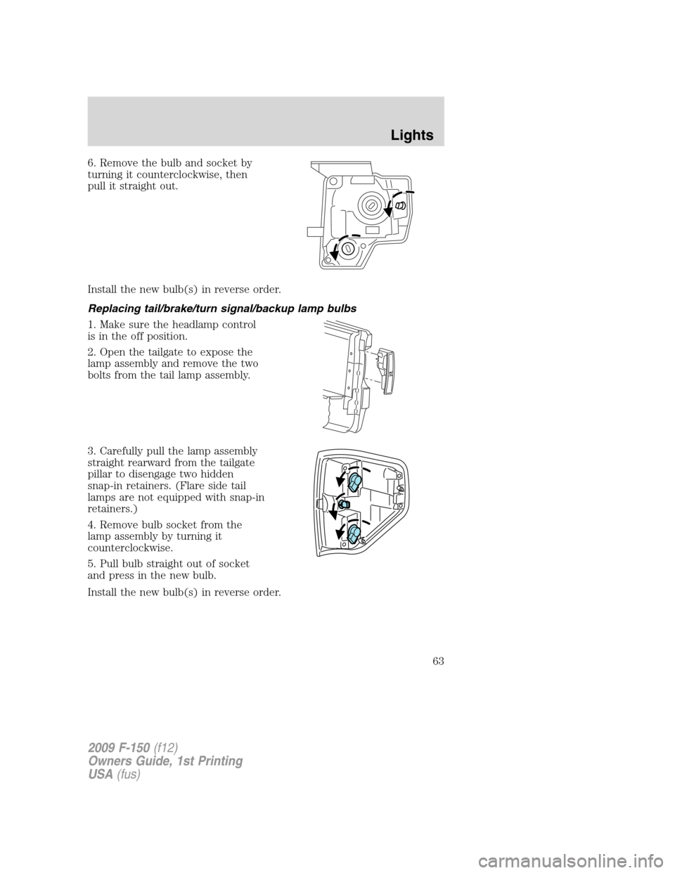
6. Remove the bulb and socket by
turning it counterclockwise, then
pull it straight out.
Install the new bulb(s) in reverse order.
Replacing tail/brake/turn signal/backup lamp bulbs
1. Make sure the headlamp control
is in the off position.
2. Open the tailgate to expose the
lamp assembly and remove the two
bolts from the tail lamp assembly.
3. Carefully pull the lamp assembly
straight rearward from the tailgate
pillar to disengage two hidden
snap-in retainers. (Flare side tail
lamps are not equipped with snap-in
retainers.)
4. Remove bulb socket from the
lamp assembly by turning it
counterclockwise.
5. Pull bulb straight out of socket
and press in the new bulb.
Install the new bulb(s) in reverse order.
2009 F-150(f12)
Owners Guide, 1st Printing
USA(fus)
Lights
63
Page 64 of 405
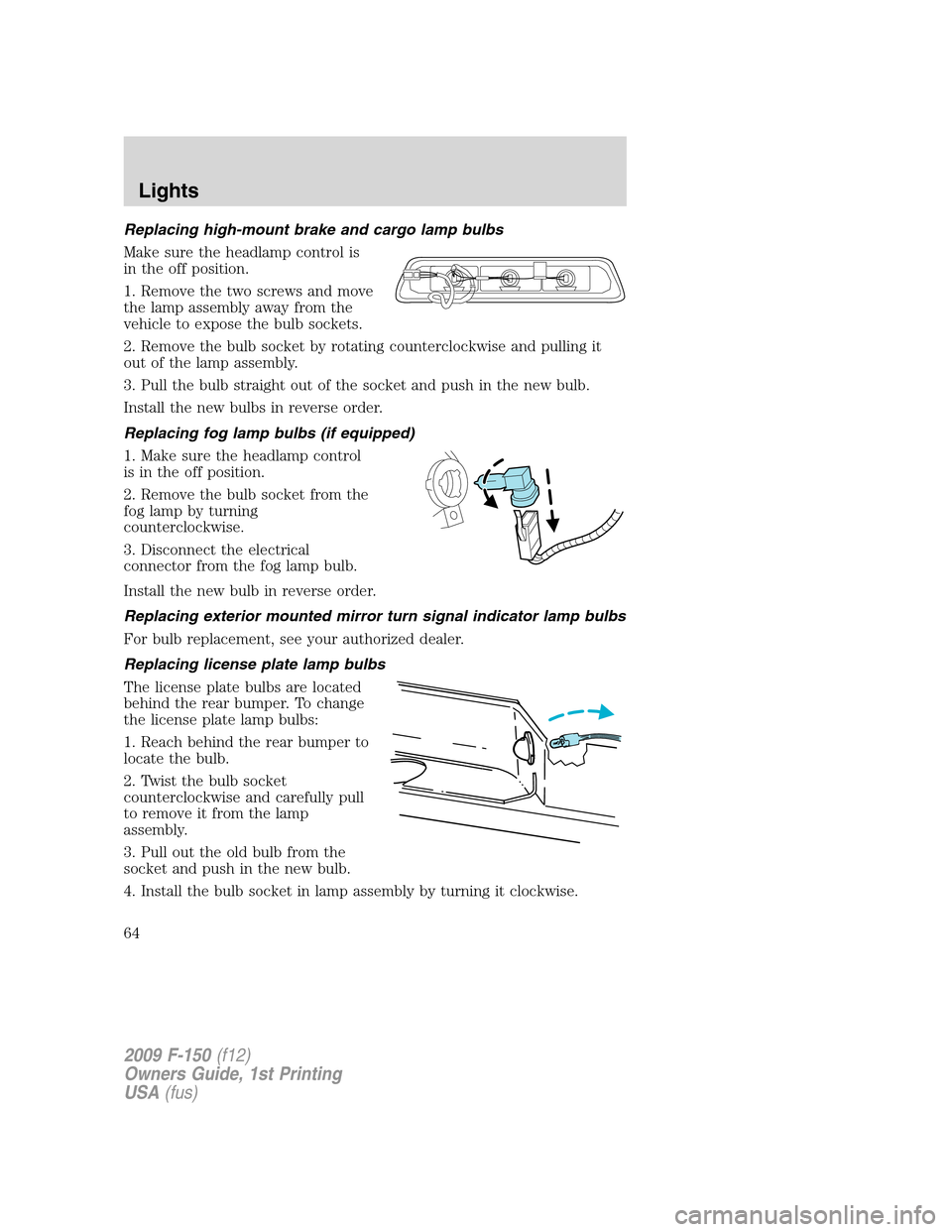
Replacing high-mount brake and cargo lamp bulbs
Make sure the headlamp control is
in the off position.
1. Remove the two screws and move
the lamp assembly away from the
vehicle to expose the bulb sockets.
2. Remove the bulb socket by rotating counterclockwise and pulling it
out of the lamp assembly.
3. Pull the bulb straight out of the socket and push in the new bulb.
Install the new bulbs in reverse order.
Replacing fog lamp bulbs (if equipped)
1. Make sure the headlamp control
is in the off position.
2. Remove the bulb socket from the
fog lamp by turning
counterclockwise.
3. Disconnect the electrical
connector from the fog lamp bulb.
Install the new bulb in reverse order.
Replacing exterior mounted mirror turn signal indicator lamp bulbs
For bulb replacement, see your authorized dealer.
Replacing license plate lamp bulbs
The license plate bulbs are located
behind the rear bumper. To change
the license plate lamp bulbs:
1. Reach behind the rear bumper to
locate the bulb.
2. Twist the bulb socket
counterclockwise and carefully pull
to remove it from the lamp
assembly.
3. Pull out the old bulb from the
socket and push in the new bulb.
4. Install the bulb socket in lamp assembly by turning it clockwise.
2009 F-150(f12)
Owners Guide, 1st Printing
USA(fus)
Lights
64
Page 65 of 405
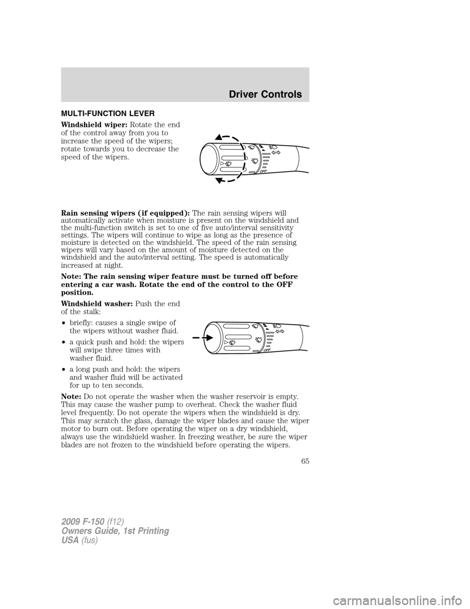
MULTI-FUNCTION LEVER
Windshield wiper:Rotate the end
of the control away from you to
increase the speed of the wipers;
rotate towards you to decrease the
speed of the wipers.
Rain sensing wipers (if equipped):The rain sensing wipers will
automatically activate when moisture is present on the windshield and
the multi-function switch is set to one of five auto/interval sensitivity
settings. The wipers will continue to wipe as long as the presence of
moisture is detected on the windshield. The speed of the rain sensing
wipers will vary based on the amount of moisture detected on the
windshield and the auto/interval setting. The speed is automatically
increased at night.
Note: The rain sensing wiper feature must be turned off before
entering a car wash. Rotate the end of the control to the OFF
position.
Windshield washer:Push the end
of the stalk:
•briefly: causes a single swipe of
the wipers without washer fluid.
•a quick push and hold: the wipers
will swipe three times with
washer fluid.
•a long push and hold: the wipers
and washer fluid will be activated
for up to ten seconds.
Note:Do not operate the washer when the washer reservoir is empty.
This may cause the washer pump to overheat. Check the washer fluid
level frequently. Do not operate the wipers when the windshield is dry.
This may scratch the glass, damage the wiper blades and cause the wiper
motor to burn out. Before operating the wiper on a dry windshield,
always use the windshield washer. In freezing weather, be sure the wiper
blades are not frozen to the windshield before operating the wipers.
2009 F-150(f12)
Owners Guide, 1st Printing
USA(fus)
Driver Controls
65
Page 66 of 405
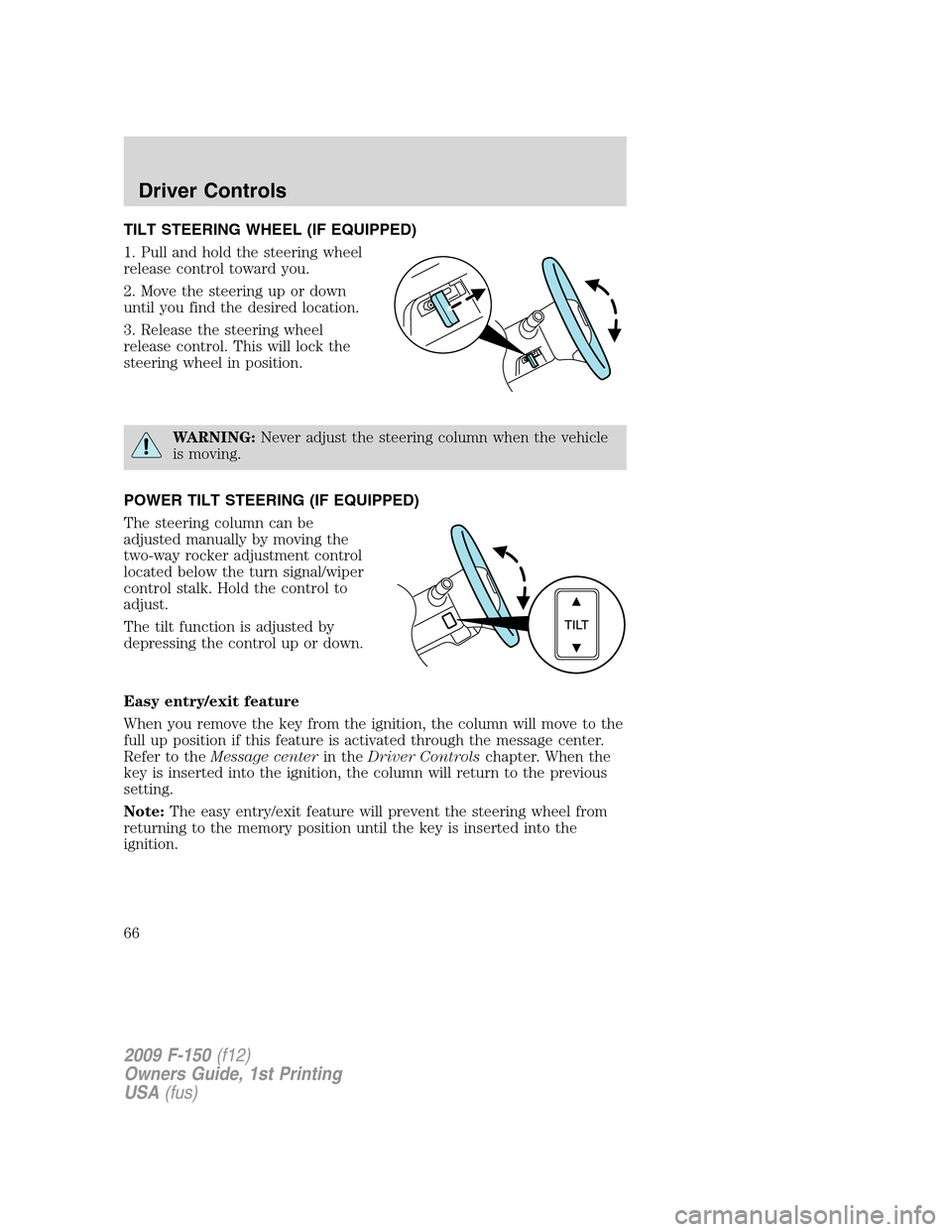
TILT STEERING WHEEL (IF EQUIPPED)
1. Pull and hold the steering wheel
release control toward you.
2. Move the steering up or down
until you find the desired location.
3. Release the steering wheel
release control. This will lock the
steering wheel in position.
WARNING:Never adjust the steering column when the vehicle
is moving.
POWER TILT STEERING (IF EQUIPPED)
The steering column can be
adjusted manually by moving the
two-way rocker adjustment control
located below the turn signal/wiper
control stalk. Hold the control to
adjust.
The tilt function is adjusted by
depressing the control up or down.
Easy entry/exit feature
When you remove the key from the ignition, the column will move to the
full up position if this feature is activated through the message center.
Refer to theMessage centerin theDriver Controlschapter. When the
key is inserted into the ignition, the column will return to the previous
setting.
Note:The easy entry/exit feature will prevent the steering wheel from
returning to the memory position until the key is inserted into the
ignition.
2009 F-150(f12)
Owners Guide, 1st Printing
USA(fus)
Driver Controls
66
Page 67 of 405
Memory feature
The steering column positions are saved when doing a memory set
function and can be recalled along with the vehicle personality features
when a memory position is selected through the remote entry
transmitter, keyless entry keypad or memory switch on the side of the
driver’s seat (if equipped with memory feature). Refer toMemory
seat/power mirrors/adjustable pedalsin theSeating and Safety
Restraintschapter.
If the steering column adjustment control is pressed during memory
recall it will cancel the automatic operation and the column will respond
to manual adjustment of the control.
WARNING:Never adjust the steering column when the vehicle
is moving.
On vehicles with memory feature, to prevent damage to the steering
column, the steering column is designed to set a stopping position just
short of the end of the column position. If the steering column
encounters an object while moving up or down, a new stopping position
will be set. To reset the steering column to its normal stopping position:
•After encountering the new stopping position, press the steering
column control again to override.
•Continue pressing the control until it reaches the end of the column
position.
•Continue pressing the control for approximately two seconds. You will
feel the steering column bounce back slightly.
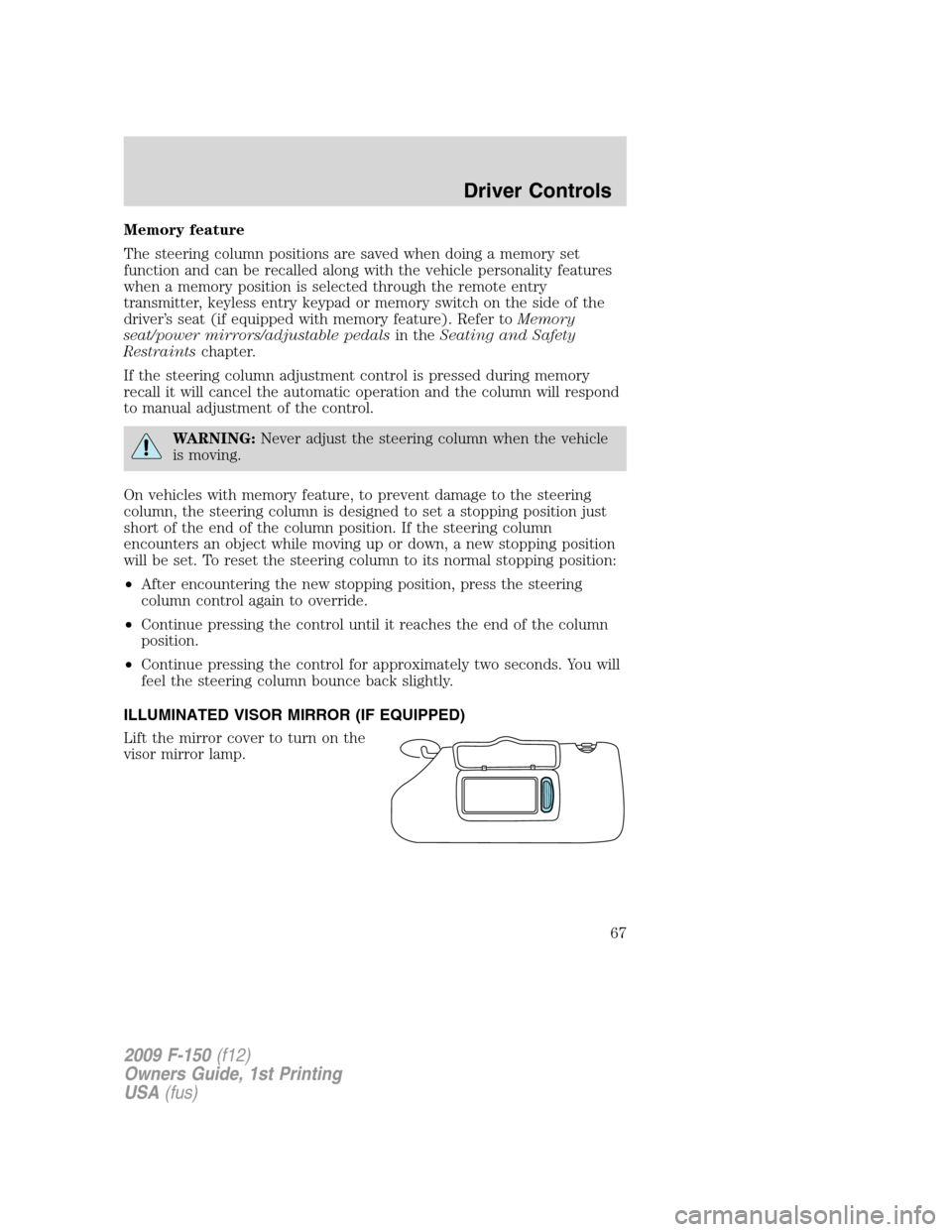
ILLUMINATED VISOR MIRROR (IF EQUIPPED)
Lift the mirror cover to turn on the
visor mirror lamp.
2009 F-150(f12)
Owners Guide, 1st Printing
USA(fus)
Driver Controls
67
Page 68 of 405
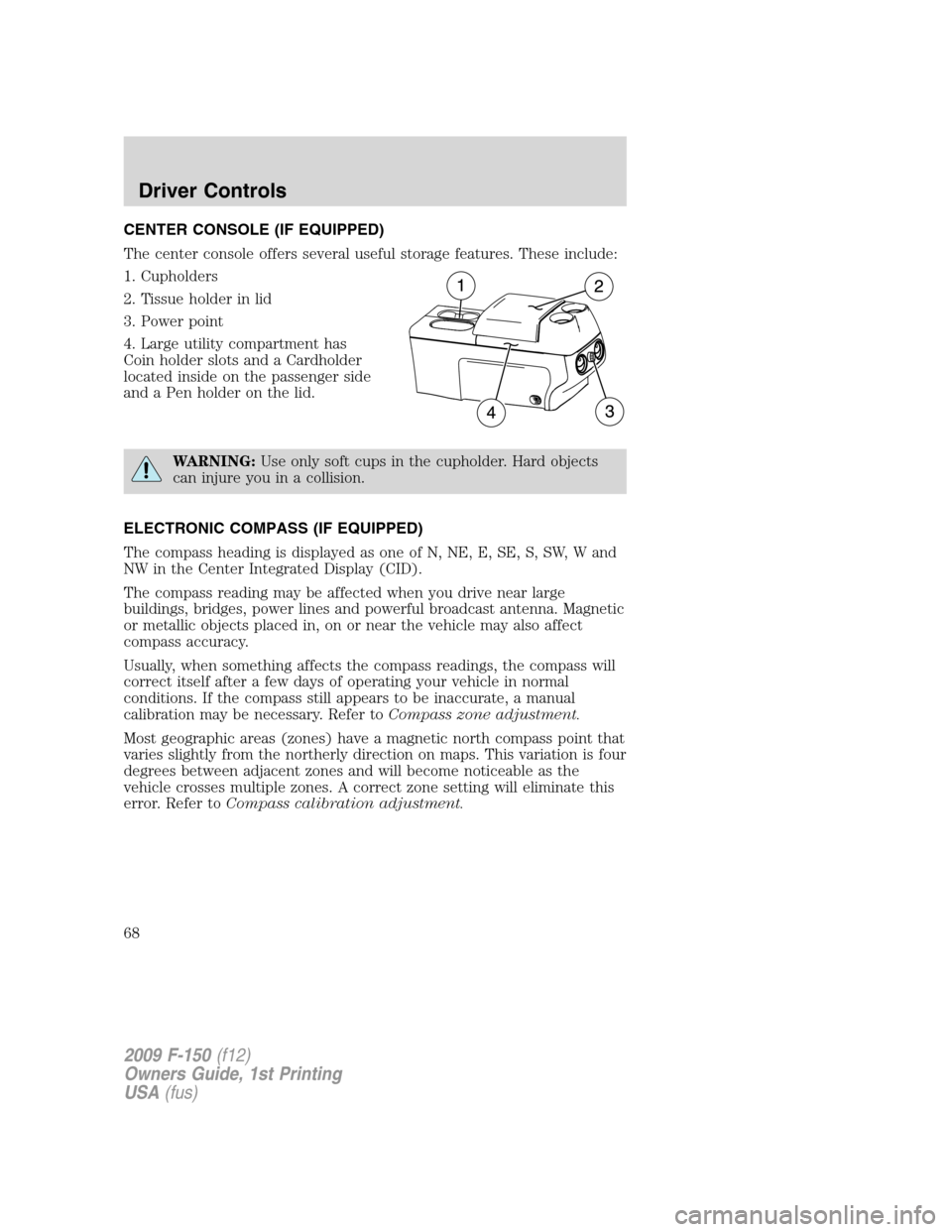
CENTER CONSOLE (IF EQUIPPED)
The center console offers several useful storage features. These include:
1. Cupholders
2. Tissue holder in lid
3. Power point
4. Large utility compartment has
Coin holder slots and a Cardholder
located inside on the passenger side
and a Pen holder on the lid.
WARNING:Use only soft cups in the cupholder. Hard objects
can injure you in a collision.
ELECTRONIC COMPASS (IF EQUIPPED)
The compass heading is displayed as one of N, NE, E, SE, S, SW, W and
NW in the Center Integrated Display (CID).
The compass reading may be affected when you drive near large
buildings, bridges, power lines and powerful broadcast antenna. Magnetic
or metallic objects placed in, on or near the vehicle may also affect
compass accuracy.
Usually, when something affects the compass readings, the compass will
correct itself after a few days of operating your vehicle in normal
conditions. If the compass still appears to be inaccurate, a manual
calibration may be necessary. Refer toCompass zone adjustment.
Most geographic areas (zones) have a magnetic north compass point that
varies slightly from the northerly direction on maps. This variation is four
degrees between adjacent zones and will become noticeable as the
vehicle crosses multiple zones. A correct zone setting will eliminate this
error. Refer toCompass calibration adjustment.
2009 F-150(f12)
Owners Guide, 1st Printing
USA(fus)
Driver Controls
68
Page 69 of 405
Compass zone adjustment
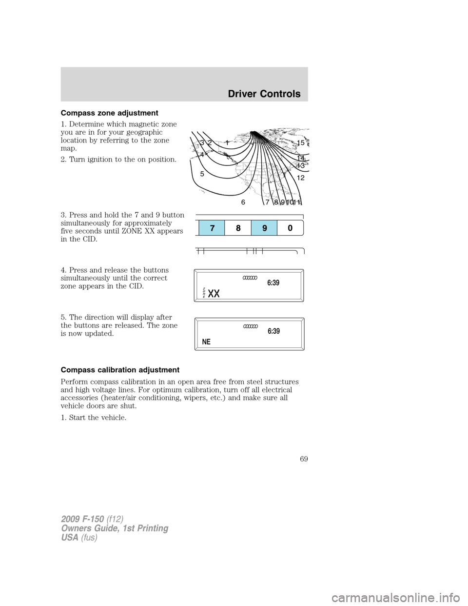
1. Determine which magnetic zone
you are in for your geographic
location by referring to the zone
map.
2. Turn ignition to the on position.
3. Press and hold the 7 and 9 button
simultaneously for approximately
five seconds until ZONE XX appears
in the CID.
4. Press and release the buttons
simultaneously until the correct
zone appears in the CID.
5. The direction will display after
the buttons are released. The zone
is now updated.
Compass calibration adjustment
Perform compass calibration in an open area free from steel structures
and high voltage lines. For optimum calibration, turn off all electrical
accessories (heater/air conditioning, wipers, etc.) and make sure all
vehicle doors are shut.
1. Start the vehicle.
1 2 3
4
5
6 7 8 9 101112 13 14 15
2009 F-150(f12)
Owners Guide, 1st Printing
USA(fus)
Driver Controls
69
Page 70 of 405
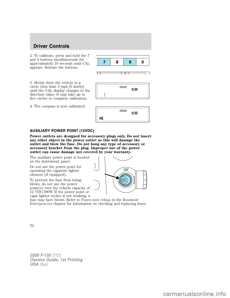
2. To calibrate, press and hold the 7
and 9 buttons simultaneously for
approximately 10 seconds until CAL
appears. Release the buttons.
3. Slowly drive the vehicle in a
circle (less than 3 mph [5 km/h])
until the CAL display changes to the
direction value. It may take up to
five circles to complete calibration.
4. The compass is now calibrated.
AUXILIARY POWER POINT (12VDC)
Power outlets are designed for accessory plugs only. Do not insert
any other object in the power outlet as this will damage the
outlet and blow the fuse. Do not hang any type of accessory or
accessory bracket from the plug. Improper use of the power
outlet can cause damage not covered by your warranty.
The auxiliary power point is located
on the instrument panel.
Do not use the power point for
operating the cigarette lighter
element (if equipped).
To prevent the fuse from being
blown, do not use the power
point(s) over the vehicle capacity of
12 VDC/180W. If the power point or
cigar lighter socket is not working, a
fuse may have blown. Refer toFuses and relaysin theRoadside
Emergencieschapter for information on checking and replacing fuses.
2009 F-150(f12)
Owners Guide, 1st Printing
USA(fus)
Driver Controls
70