FORD F250 2002 Owners Manual
Manufacturer: FORD, Model Year: 2002, Model line: F250, Model: FORD F250 2002Pages: 264, PDF Size: 2.37 MB
Page 161 of 264
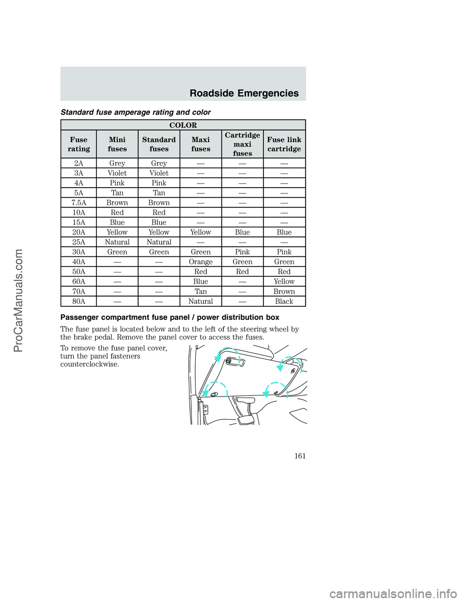
Standard fuse amperage rating and color
COLOR
Fuse
ratingMini
fusesStandard
fusesMaxi
fusesCartridge
maxi
fusesFuse link
cartridge
2A Grey Grey — — —
3A Violet Violet — — —
4A Pink Pink — — —
5A Tan Tan — — —
7.5A Brown Brown — — —
10A Red Red — — —
15A Blue Blue — — —
20A Yellow Yellow Yellow Blue Blue
25A Natural Natural — — —
30A Green Green Green Pink Pink
40A — — Orange Green Green
50A — — Red Red Red
60A — — Blue — Yellow
70A — — Tan — Brown
80A — — Natural — Black
Passenger compartment fuse panel / power distribution box
The fuse panel is located below and to the left of the steering wheel by
the brake pedal. Remove the panel cover to access the fuses.
To remove the fuse panel cover,
turn the panel fasteners
counterclockwise.
Roadside Emergencies
161
ProCarManuals.com
Page 162 of 264
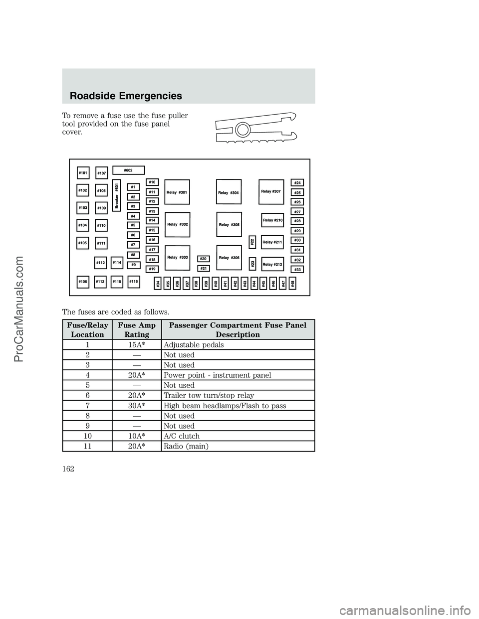
To remove a fuse use the fuse puller
tool provided on the fuse panel
cover.
The fuses are coded as follows.
Fuse/Relay
LocationFuse Amp
RatingPassenger Compartment Fuse Panel
Description
1 15A* Adjustable pedals
2 — Not used
3 — Not used
4 20A* Power point - instrument panel
5 — Not used
6 20A* Trailer tow turn/stop relay
7 30A* High beam headlamps/Flash to pass
8 — Not used
9 — Not used
10 10A* A/C clutch
11 20A* Radio (main)
Roadside Emergencies
162
ProCarManuals.com
Page 163 of 264
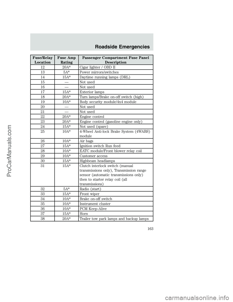
Fuse/Relay
LocationFuse Amp
RatingPassenger Compartment Fuse Panel
Description
12 20A* Cigar lighter / OBD II
13 5A* Power mirrors/switches
14 15A* Daytime running lamps (DRL)
15 — Not used
16 — Not used
17 15A* Exterior lamps
18 20A* Turn lamps/Brake on-off switch (high)
19 10A* Body security module/4x4 module
20 — Not used
21 — Not used
22 20A* Engine control
23 20A* Engine control (gasoline engine only)
24 15A* Not used (spare)
25 10A* 4-Wheel Anti-lock Brake System (4WABS)
module
26 10A* Air bags
27 15A* Ignition switch Run feed
28 10A* EATC module/Front blower relay coil
29 10A* Customer access
30 15A* Highbeam headlamps
31 15A* Clutch interlock switch (manual
transmissions only), Transmission range
sensor (automatic transmissions only)
then to starter relay coil (all
transmissions)
32 5A* Radio (start)
33 15A* Front wiper
34 10A* Brake on-off switch
35 10A* Instrument cluster
36 10A* PCM Keep-Alive
37 15A* Horn
38 20A* Trailer tow park lamps and backup lamps
Roadside Emergencies
163
ProCarManuals.com
Page 164 of 264
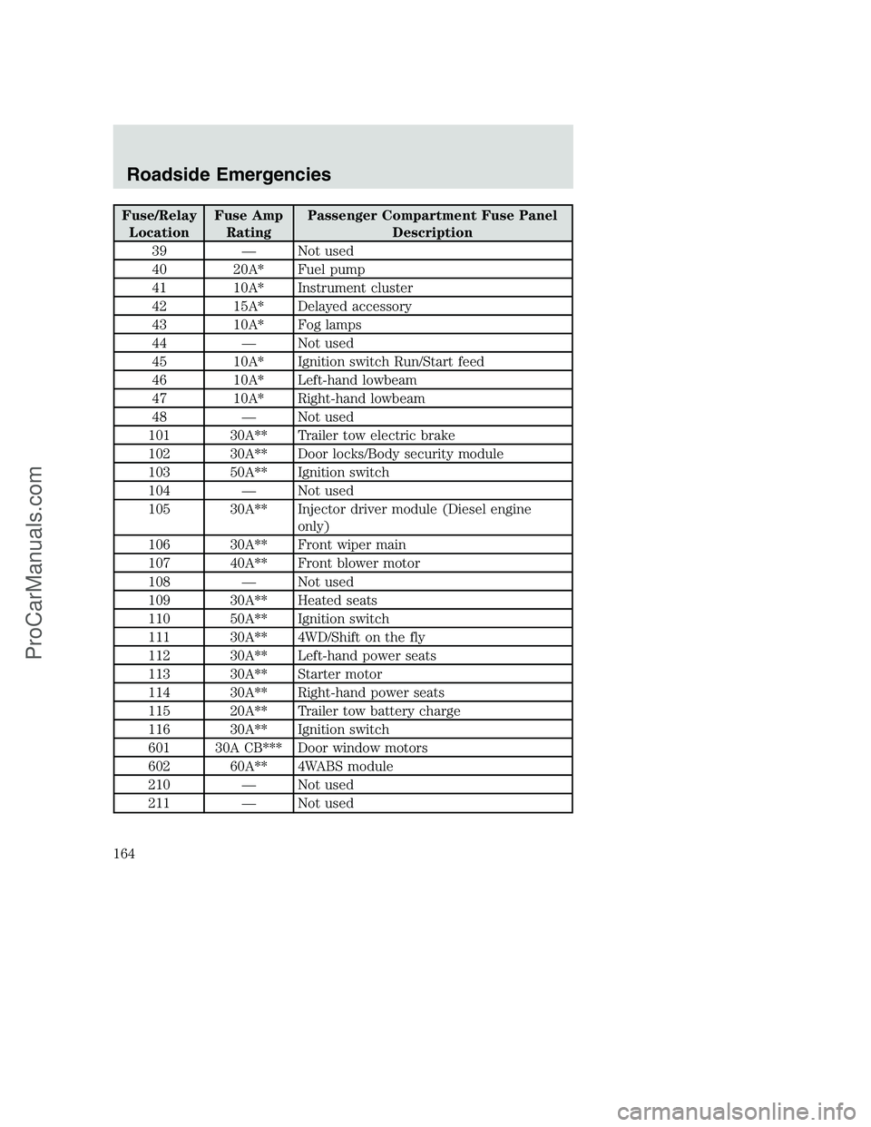
Fuse/Relay
LocationFuse Amp
RatingPassenger Compartment Fuse Panel
Description
39 — Not used
40 20A* Fuel pump
41 10A* Instrument cluster
42 15A* Delayed accessory
43 10A* Fog lamps
44 — Not used
45 10A* Ignition switch Run/Start feed
46 10A* Left-hand lowbeam
47 10A* Right-hand lowbeam
48 — Not used
101 30A** Trailer tow electric brake
102 30A** Door locks/Body security module
103 50A** Ignition switch
104 — Not used
105 30A** Injector driver module (Diesel engine
only)
106 30A** Front wiper main
107 40A** Front blower motor
108 — Not used
109 30A** Heated seats
110 50A** Ignition switch
111 30A** 4WD/Shift on the fly
112 30A** Left-hand power seats
113 30A** Starter motor
114 30A** Right-hand power seats
115 20A** Trailer tow battery charge
116 30A** Ignition switch
601 30A CB*** Door window motors
602 60A** 4WABS module
210 — Not used
211 — Not used
Roadside Emergencies
164
ProCarManuals.com
Page 165 of 264
Fuse/Relay
LocationFuse Amp
RatingPassenger Compartment Fuse Panel
Description
212 — Not used
301 — Front blower motor relay
302 — Powertrain (EEC) relay
303 — Injector driver module relay (Diesel engine
only)
304 — Not used
305 — Trailer tow battery charge relay
306 — Delayed accessory relay
307 — Starter relay
* Mini Fuses ** Maxi Fuses ***Circuit Breaker
CHANGING A FLAT TIRE
If you get a flat tire while driving:
•do not brake heavily.
•gradually decrease the vehicle’s speed.
•hold the steering wheel firmly.
•slowly move to a safe place on the side of the road.
The use of tire sealants is not recommended and may
compromise the integrity of your tires. The use of tire sealants
may also affect your tire pressure monitoring system (if equipped).
Spare tire information
Your vehicle may be equipped with a spare tire that can be used as
either a spare or a regular tire. The spare tire is not equipped with wheel
trim. The wheel trim from the original wheel/tire may be used on the
spare.
If your vehicle is equipped with 4WD, a spare tire of a different
size than the road tires should not be used. Use of such a tire
could result in damage to driveline components and an increased risk
of loss of vehicle control, vehicle rollover, personal injury or death.
Roadside Emergencies
165
ProCarManuals.com
Page 166 of 264
If your vehicle is equipped with a tire pressure monitoring
system, refer to Tire Pressure Monitoring System (if equipped)
in the Maintenance and specifications section for important information
before changing your tires. If the tire pressure monitoring system
becomes damaged, it will no longer function.
Location of the spare tire and tools
The spare tire and tools for your vehicle are stowed in the following
locations:
Tool Location
Spare tire (pick-up trucks only) Under the vehicle, just forward of
the rear bumper
Jack, jack handle and lug wrench Regular cab, crew cab and
SuperCab without rear bench seat:
Fastened to floor pan behind
rearmost seat on passenger side
SuperCab with rear bench seat:
Under rear bench on passenger
side
Key, spare tire lock In the glove box
Removing the spare tire (with spare tire carrier only)
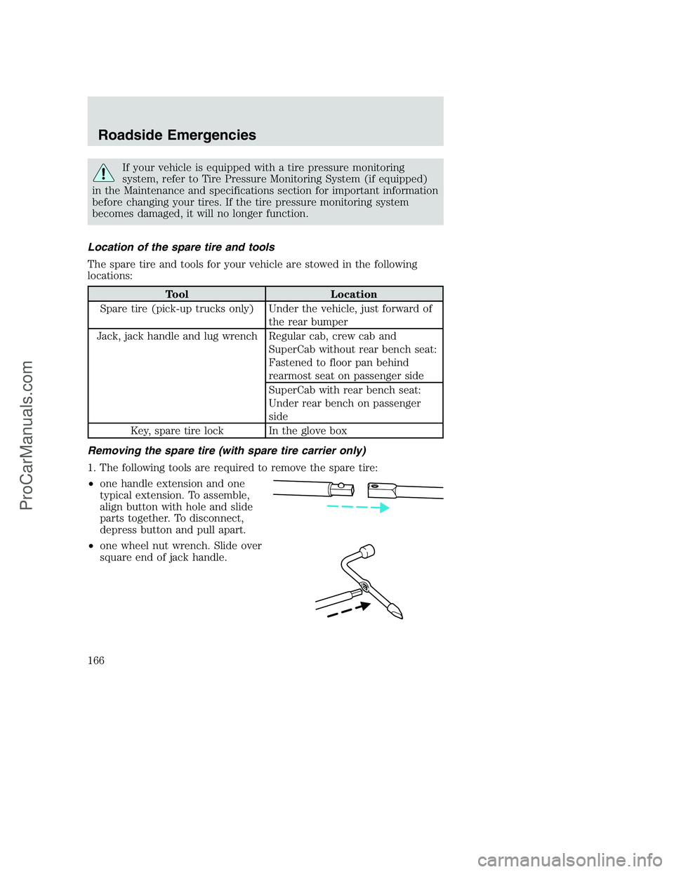
1. The following tools are required to remove the spare tire:
•one handle extension and one
typical extension. To assemble,
align button with hole and slide
parts together. To disconnect,
depress button and pull apart.
•one wheel nut wrench. Slide over
square end of jack handle.
Roadside Emergencies
166
ProCarManuals.com
Page 167 of 264
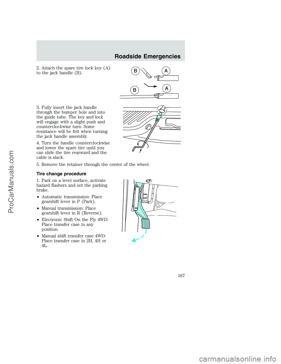
2. Attach the spare tire lock key (A)
to the jack handle (B).
3. Fully insert the jack handle
through the bumper hole and into
the guide tube. The key and lock
will engage with a slight push and
counterclockwise turn. Some
resistance will be felt when turning
the jack handle assembly.
4. Turn the handle counterclockwise
and lower the spare tire until you
can slide the tire rearward and the
cable is slack.
5. Remove the retainer through the center of the wheel.
Tire change procedure
1. Park on a level surface, activate
hazard flashers and set the parking
brake.
•Automatic transmission: Place
gearshift lever in P (Park).
•Manual transmission: Place
gearshift lever in R (Reverse).
•Electronic Shift On the Fly 4WD:
Place transfer case in any
position.
•Manual shift transfer case 4WD:
Place transfer case in 2H, 4H or
4L.
Roadside Emergencies
167
ProCarManuals.com
Page 168 of 264
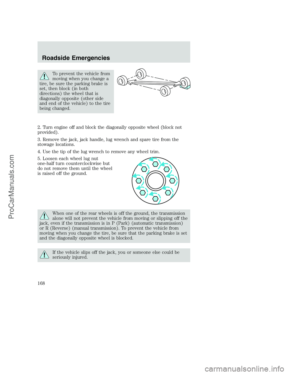
To prevent the vehicle from
moving when you change a
tire, be sure the parking brake is
set, then block (in both
directions) the wheel that is
diagonally opposite (other side
and end of the vehicle) to the tire
being changed.
2. Turn engine off and block the diagonally opposite wheel (block not
provided).
3. Remove the jack, jack handle, lug wrench and spare tire from the
stowage locations.
4. Use the tip of the lug wrench to remove any wheel trim.
5. Loosen each wheel lug nut
one-half turn counterclockwise but
do not remove them until the wheel
is raised off the ground.
When one of the rear wheels is off the ground, the transmission
alone will not prevent the vehicle from moving or slipping off the
jack, even if the transmission is in P (Park) (automatic transmission)
or R (Reverse) (manual transmission). To prevent the vehicle from
moving when you change the tire, be sure that the parking brake is set
and the diagonally opposite wheel is blocked.
If the vehicle slips off the jack, you or someone else could be
seriously injured.
Roadside Emergencies
168
ProCarManuals.com
Page 169 of 264
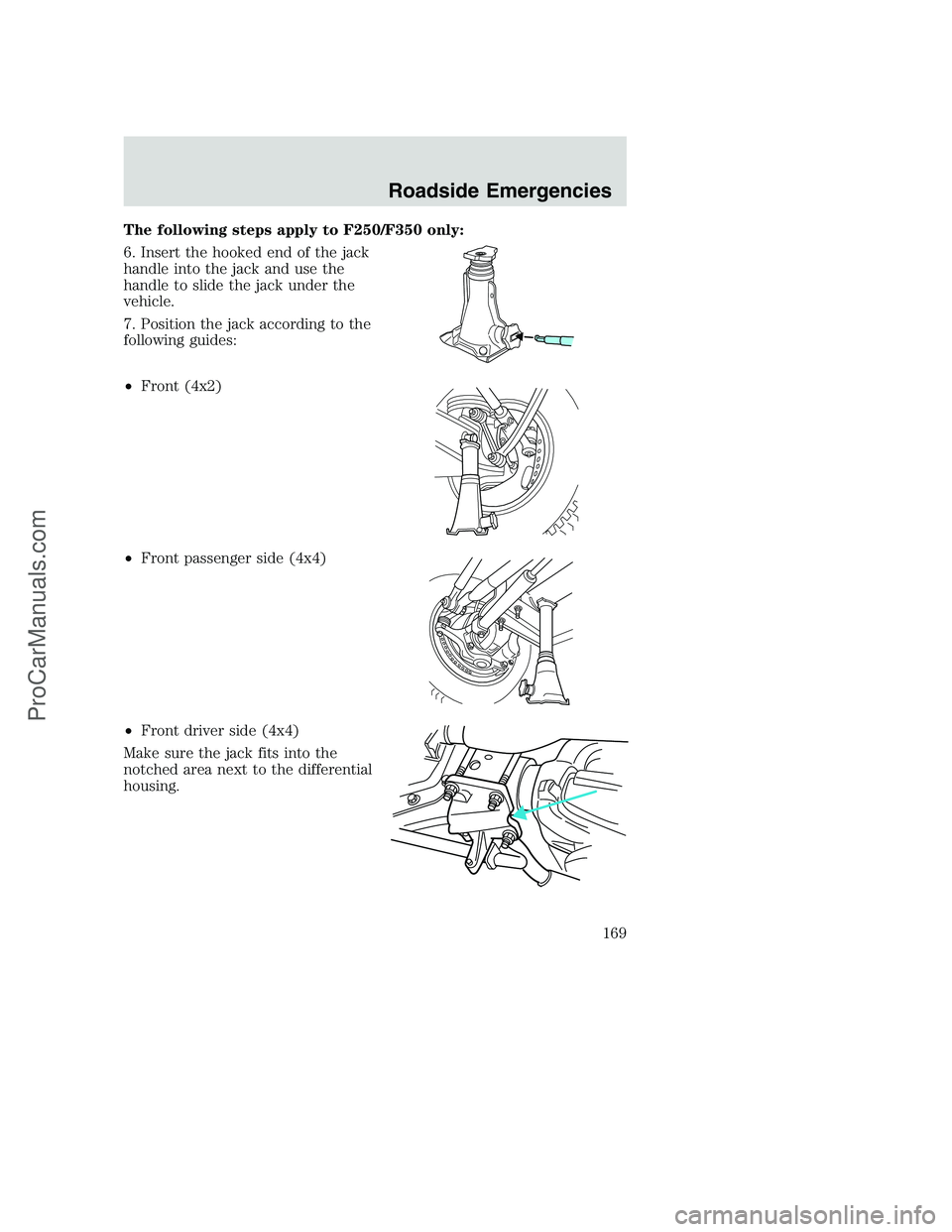
The following steps apply to F250/F350 only:
6. Insert the hooked end of the jack
handle into the jack and use the
handle to slide the jack under the
vehicle.
7. Position the jack according to the
following guides:
•Front (4x2)
•Front passenger side (4x4)
•Front driver side (4x4)
Make sure the jack fits into the
notched area next to the differential
housing.
Roadside Emergencies
169
ProCarManuals.com
Page 170 of 264
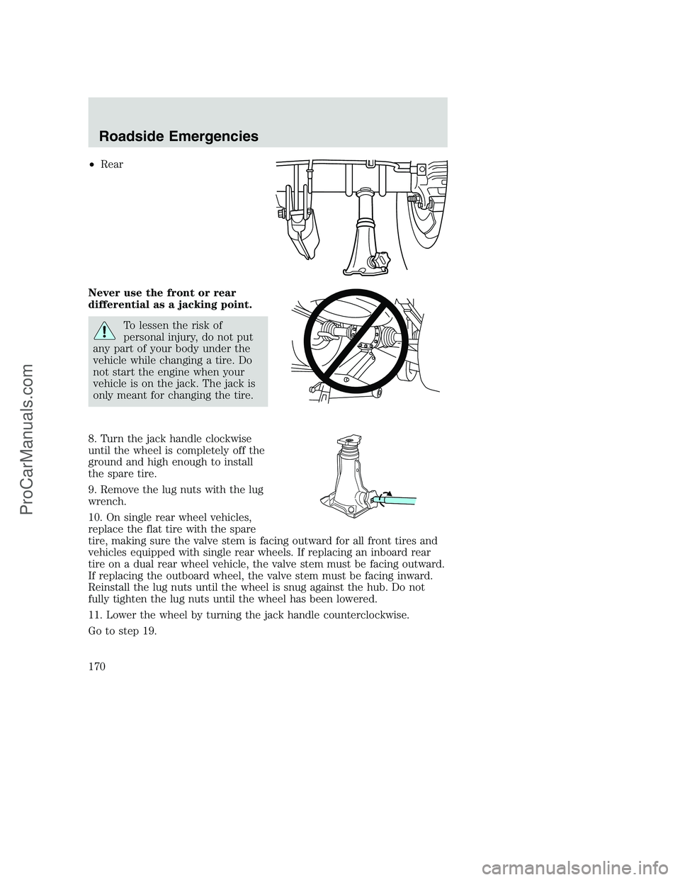
•Rear
Never use the front or rear
differential as a jacking point.
To lessen the risk of
personal injury, do not put
any part of your body under the
vehicle while changing a tire. Do
not start the engine when your
vehicle is on the jack. The jack is
only meant for changing the tire.
8. Turn the jack handle clockwise
until the wheel is completely off the
ground and high enough to install
the spare tire.
9. Remove the lug nuts with the lug
wrench.
10. On single rear wheel vehicles,
replace the flat tire with the spare
tire, making sure the valve stem is facing outward for all front tires and
vehicles equipped with single rear wheels. If replacing an inboard rear
tire on a dual rear wheel vehicle, the valve stem must be facing outward.
If replacing the outboard wheel, the valve stem must be facing inward.
Reinstall the lug nuts until the wheel is snug against the hub. Do not
fully tighten the lug nuts until the wheel has been lowered.
11. Lower the wheel by turning the jack handle counterclockwise.
Go to step 19.
Roadside Emergencies
170
ProCarManuals.com