FORD F250 2005 Owners Manual
Manufacturer: FORD, Model Year: 2005, Model line: F250, Model: FORD F250 2005Pages: 312, PDF Size: 2.86 MB
Page 211 of 312
pressure for the tire and associated load rating is imprinted on the tire
sidewall. Tire air pressure may require re-adjustment within these
pressure limits to accommodate the additional weight of the snowplow
installation.
•Federal and some local regulations require additional exterior lamps
for snowplow-equipped vehicles. Consult your dealer for additional
information.
Operating the vehicle with the snowplow attached
Do not use your vehicle for snow removal until it has been driven at
least 500 miles (800 km).
The attached snowplow blade restricts airflow to the radiator, and may
cause the engine to run at a higher temperature:
•If you are driving more than 15 miles (24 km) where outside air
temperatures are above freezing, then angle the plow blade to full left
or right to maximize airflow to the radiator.
•If you are driving less than 15 miles (24 km) at speeds up to 40 mph
(64 km/h) in cold weather you will not need to adjust blade position
Follow the severe duty schedule in yourScheduled Maintenance Guide
for engine oil and transmission fluid change intervals.
Snowplowing with your air bag-equipped vehicle
Your vehicle is equipped with a driver and passenger air bag
Supplemental Restraint System (SRS) The SRS is designed to activate in
certain frontal and offset frontal collisions when the vehicle sustains
sufficient longitudinal deceleration.
Careless or high speed driving while plowing snow which results in
sufficient vehicle decelerations can deploy the air bag. Such driving also
increases the risk of accidents.
All occupants of the vehicle, including the driver, should always
properly wear their safety belts, even when an air bag
supplemental restraint system (SRS) is provided.
Never remove or defeat the “tripping mechanisms” designed into the
snow removal equipment by its manufacturer. Doing so may cause
damage to the vehicle and the snow removal equipment as well as
possible air bag deployment.
2005 F250/350/450/550(f23)
Owners Guide (post-2002-fmt)
USA_English(fus)
Driving
211
Page 212 of 312
Do not attempt to service, repair, or modify the air bag
supplemental restraint system (SRS) or its fuses. See your Ford
or Lincoln Mercury dealer.
Additional equipment such as snowplow equipment may effect
the performance of the air bag sensors increasing the risk of
injury. Please refer to theBody Builders Layout Bookfor instructions
about the appropriate installation of additional equipment.
Transmission operation while plowing
•Shift transfer case to 4x4 LOW (4WD Low) when plowing in small
areas at speeds below 5 mph (8 km/h).
•
Shift transfer case to 4x4 HIGH (4WD High) when plowing larger areas
or light snow at higher speeds. Do not exceed 15 mph (24 km/h).
•Do not shift the transmission from a forward gear to R (Reverse) until
the engine is at idle and the wheels are stopped.
•If the vehicle is stuck, shift the transmission in a steady motion
between forward and reverse gears. Do not rock the vehicle for more
than a few minutes. The transmission and tires may be damaged or
the engine can overheat.
Do not rock the vehicle if the engine is not at normal operating
temperature. Do not rock the vehicle for more than a minute. The
transmission and tires may be damaged or the engine may overheat.
Refer toTransmission temperature gaugein theInstrument Cluster
chapter for transmission fluid temperature information.
Do not spin the wheels at over 35 mph (55 km/h). The tires may
fail and injure a passenger or bystander.
Removing the snowplow frame mount
A metal crossmember is included below the front bumper on Super Duty
vehicles called a “BlockerBeam”. Typical snowplow installations require
removal of this BlockerBeam to install the snowplow mounting hardware
to the vehicle frame.
The BlockerBeam must be re-installed if the snowplow
frame-mounting hardware is removed from the vehicle to assure
proper air bag deployment in a crash.
2005 F250/350/450/550(f23)
Owners Guide (post-2002-fmt)
USA_English(fus)
Driving
212
Page 213 of 312
GETTING ROADSIDE ASSISTANCE
To fully assist you should you have a vehicle concern, Ford Motor
Company offers a complimentary roadside assistance program. This
program is separate from the New Vehicle Limited Warranty. The service
is available:
•24–hours, seven days a week
•for the New Vehicle Limited Warranty period of three years or 36,000
miles (60,000 km), whichever occurs first on Ford and Mercury
vehicles, and four years or 50,000 miles (80,000 km) on Lincoln
vehicles.
Roadside assistance will cover:
•a flat tire change with a good spare (except Ford GT which has a tire
inflation kit)
•battery jump start
•lock-out assistance (key replacement cost is the customer’s
responsibility)
•fuel delivery (2.0 gallons [7.5L], maximum two occurrences within 12
month period)
•towing of your disabled vehicle to the nearest Ford Motor Company
dealership, or your selling dealer if within 35 miles (56.3 km) of the
nearest Ford Motor Company dealership (one tow per disablement).
Even non-warranty related tows, like accidents, are covered (some
exclusions apply, such as impound towing or repossession).
Canadian customers refer to your Owner Information Guide for
information on:
•coverage period
•exact fuel amounts
•towing of your disabled vehicle
•emergency travel expense reimbursement
•travel planning benefits
USING ROADSIDE ASSISTANCE
Complete the roadside assistance identification card and place it in your
wallet for quick reference. In the United States, this card is found in the
Owner Guide portfolio in the glove compartment. In Canada, the card is
found in theOwner Information Guidein the glove compartment.
U.S. Ford or Mercury vehicle customers who require roadside assistance,
call 1–800–241–3673; Lincoln vehicle customers call 1–800–521–4140.
2005 F250/350/450/550(f23)
Owners Guide (post-2002-fmt)
USA_English(fus)
Roadside Emergencies
Roadside Emergencies
213
Page 214 of 312
Canadian customers who require roadside assistance, call
1–800–665–2006.
If you need to arrange roadside assistance for yourself, Ford Motor
Company will reimburse a reasonable amount. To obtain reimbursement
information, U.S. Ford or Mercury vehicles customers call
1-800-241-3673; Lincoln vehicle customers call 1–800–521–4140.
Canadian customers who need to obtain reimbursement information, call
1–800–665–2006.
ROADSIDE COVERAGE BEYOND BASIC WARRANTY
In the United States, you may purchase additional roadside assistance
coverage beyond this period through the Ford Auto Club by contacting
your Ford or Lincoln/Mercury dealer.
Similarly in Canada, for uninterrupted Roadside Assistance coverage, you
may purchase extended coverage prior to your Basic Warranty’s Roadside
Assistance expiring. For more information and enrollment, contact
1–877–294–2582 or visit our website at www.ford.ca.
HAZARD FLASHER
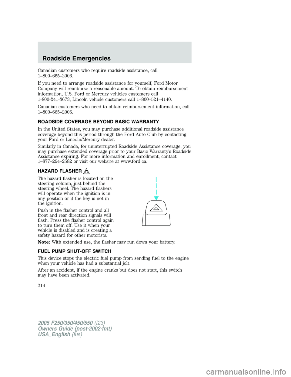
The hazard flasher is located on the
steering column, just behind the
steering wheel. The hazard flashers
will operate when the ignition is in
any position or if the key is not in
the ignition.
Push in the flasher control and all
front and rear direction signals will
flash. Press the flasher control again
to turn them off. Use it when your
vehicle is disabled and is creating a
safety hazard for other motorists.
Note:With extended use, the flasher may run down your battery.
FUEL PUMP SHUT-OFF SWITCH
This device stops the electric fuel pump from sending fuel to the engine
when your vehicle has had a substantial jolt.
After an accident, if the engine cranks but does not start, this switch
may have been activated.
2005 F250/350/450/550(f23)
Owners Guide (post-2002-fmt)
USA_English(fus)
Roadside Emergencies
214
Page 215 of 312
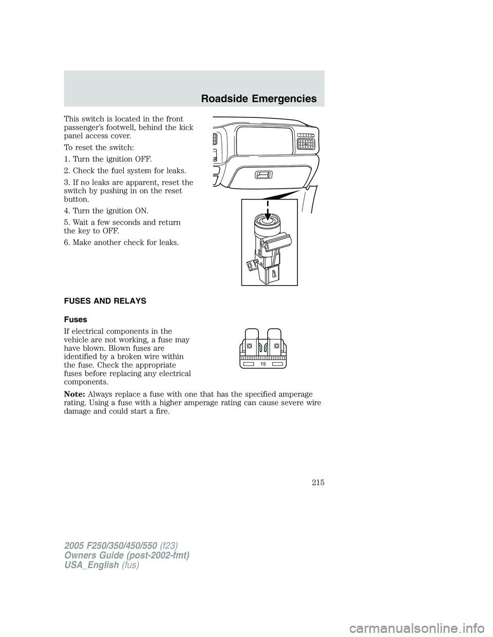
This switch is located in the front
passenger’s footwell, behind the kick
panel access cover.
To reset the switch:
1. Turn the ignition OFF.
2. Check the fuel system for leaks.
3. If no leaks are apparent, reset the
switch by pushing in on the reset
button.
4. Turn the ignition ON.
5. Wait a few seconds and return
the key to OFF.
6. Make another check for leaks.
FUSES AND RELAYS
Fuses
If electrical components in the
vehicle are not working, a fuse may
have blown. Blown fuses are
identified by a broken wire within
the fuse. Check the appropriate
fuses before replacing any electrical
components.
Note:Always replace a fuse with one that has the specified amperage
rating. Using a fuse with a higher amperage rating can cause severe wire
damage and could start a fire.
15
2005 F250/350/450/550(f23)
Owners Guide (post-2002-fmt)
USA_English(fus)
Roadside Emergencies
215
Page 216 of 312
Standard fuse amperage rating and color
COLOR
Fuse
ratingMini
fusesStandard
fusesMaxi
fusesCartridge
maxi
fusesFuse link
cartridge
2A Grey Grey — — —
3A Violet Violet — — —
4A Pink Pink — — —
5A Tan Tan — — —
7.5A Brown Brown — — —
10A Red Red — — —
15A Blue Blue — — —
20A Yellow Yellow Yellow Blue Blue
25A Natural Natural — — —
30A Green Green Green Pink Pink
40A — — Orange Green Green
50A — — Red Red Red
60A — — Blue — Yellow
70A — — Tan — Brown
80A — — Natural — Black
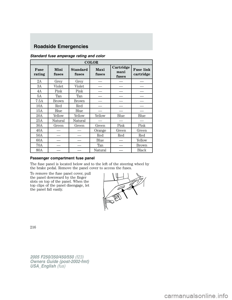
Passenger compartment fuse panel
The fuse panel is located below and to the left of the steering wheel by
the brake pedal. Remove the panel cover to access the fuses.
To remove the fuse panel cover, pull
the panel downward by the finger
slots on top of the panel. When the
top clips of the panel disengage, let
the panel fall easily.
2005 F250/350/450/550(f23)
Owners Guide (post-2002-fmt)
USA_English(fus)
Roadside Emergencies
216
Page 217 of 312
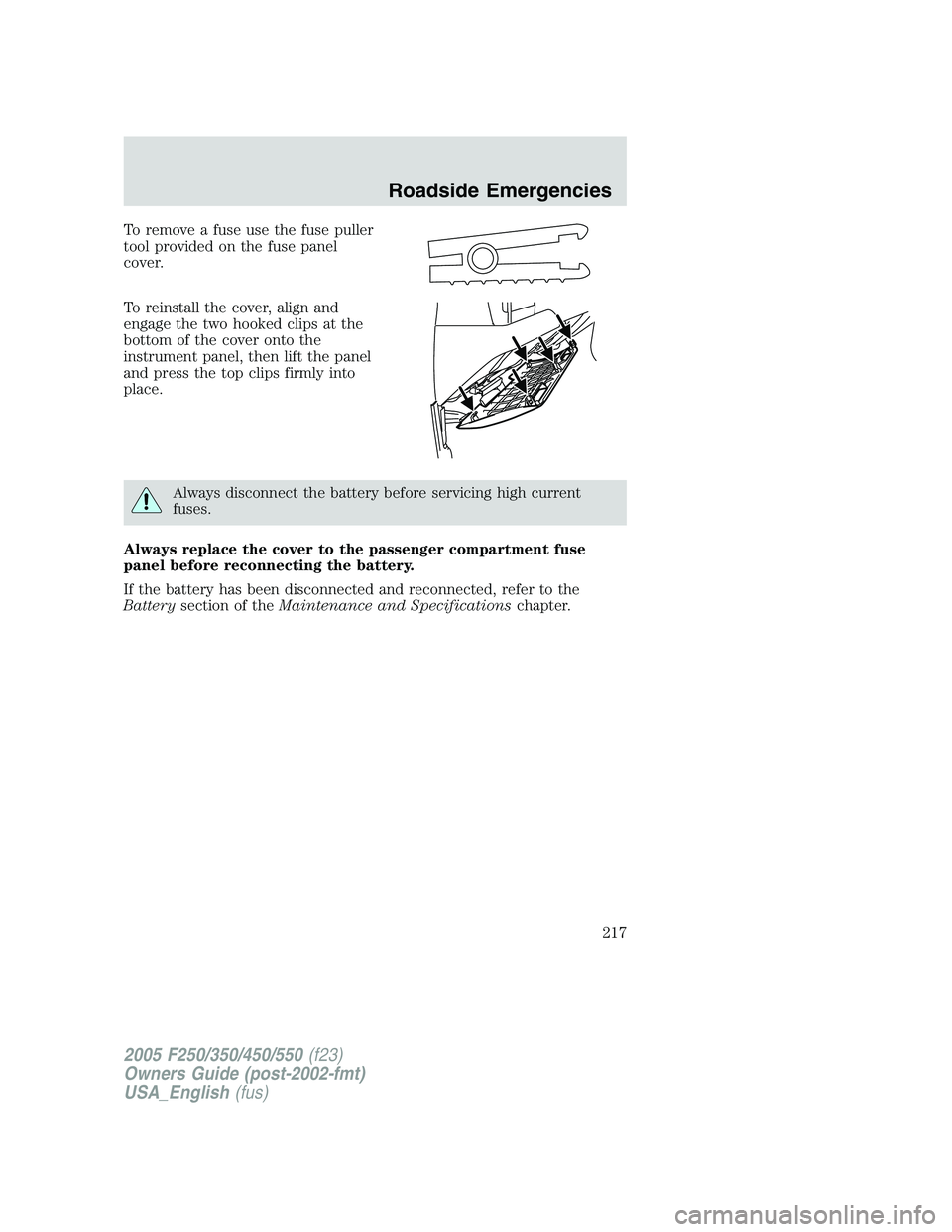
To remove a fuse use the fuse puller
tool provided on the fuse panel
cover.
To reinstall the cover, align and
engage the two hooked clips at the
bottom of the cover onto the
instrument panel, then lift the panel
and press the top clips firmly into
place.
Always disconnect the battery before servicing high current
fuses.
Always replace the cover to the passenger compartment fuse
panel before reconnecting the battery.
If the battery has been disconnected and reconnected, refer to the
Batterysection of theMaintenance and Specificationschapter.
2005 F250/350/450/550(f23)
Owners Guide (post-2002-fmt)
USA_English(fus)
Roadside Emergencies
217
Page 218 of 312
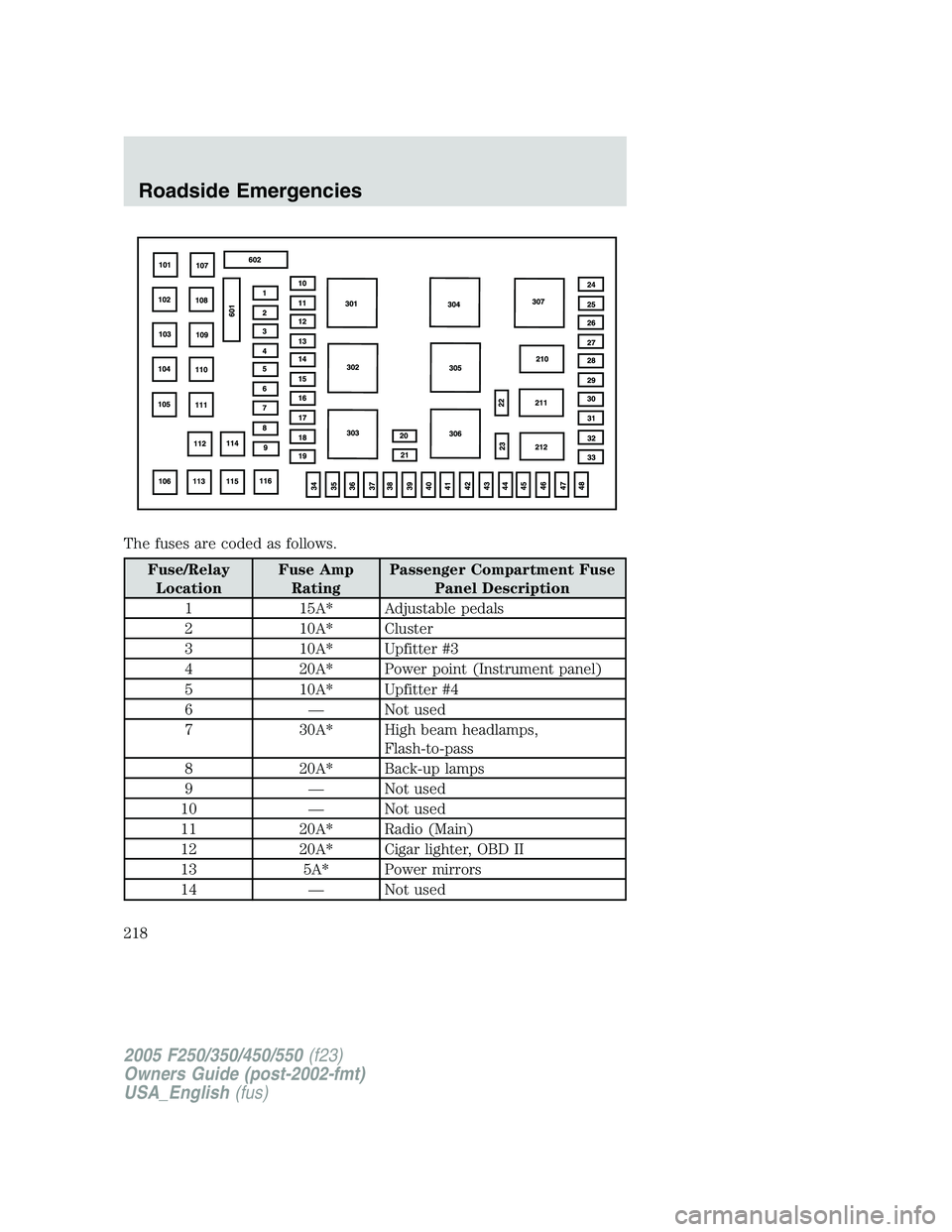
The fuses are coded as follows.
Fuse/Relay
LocationFuse Amp
RatingPassenger Compartment Fuse
Panel Description
1 15A* Adjustable pedals
2 10A* Cluster
3 10A* Upfitter #3
4 20A* Power point (Instrument panel)
5 10A* Upfitter #4
6 — Not used
7 30A* High beam headlamps,
Flash-to-pass
8 20A* Back-up lamps
9 — Not used
10 — Not used
11 20A* Radio (Main)
12 20A* Cigar lighter, OBD II
13 5A* Power mirrors
14 — Not used
2005 F250/350/450/550(f23)
Owners Guide (post-2002-fmt)
USA_English(fus)
Roadside Emergencies
218
Page 219 of 312
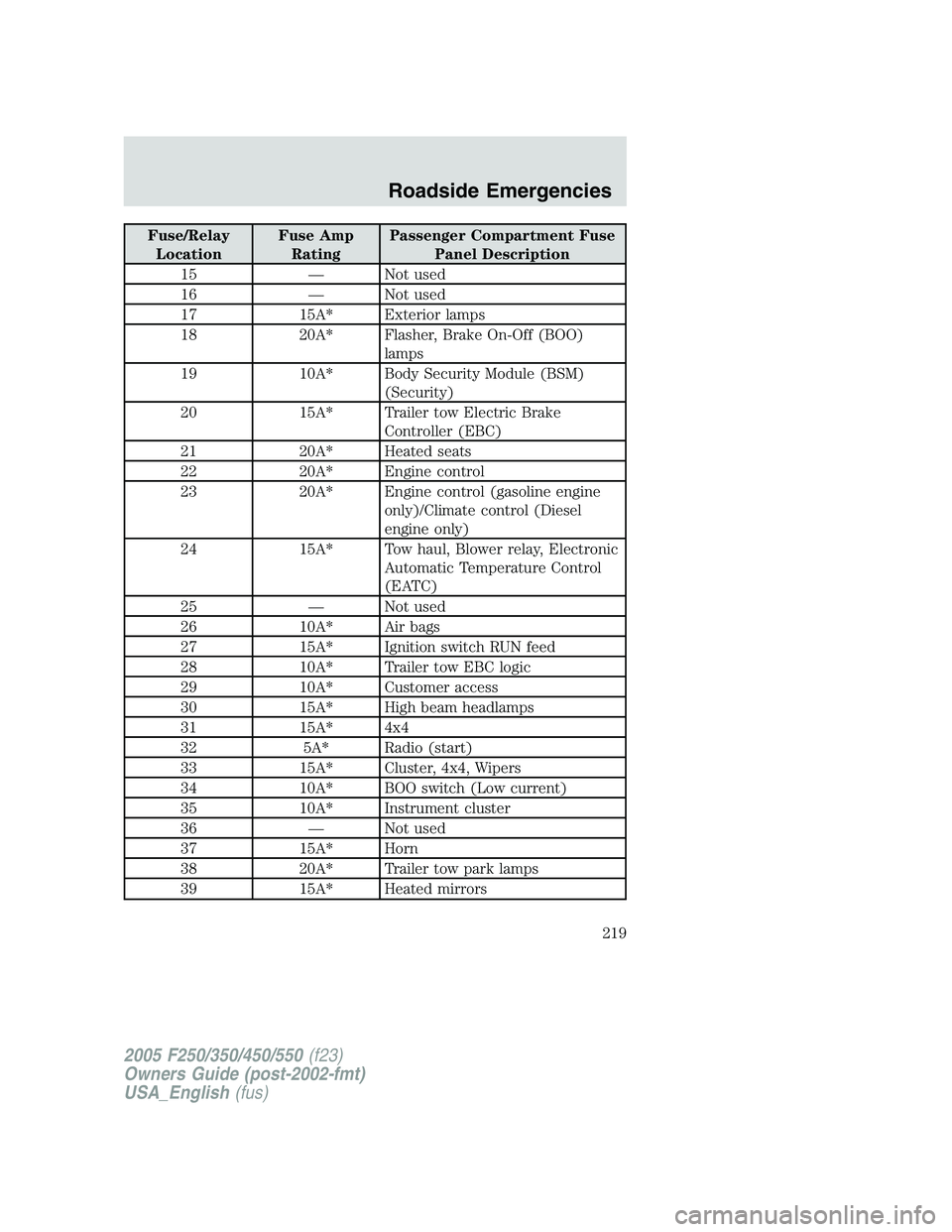
Fuse/Relay
LocationFuse Amp
RatingPassenger Compartment Fuse
Panel Description
15 — Not used
16 — Not used
17 15A* Exterior lamps
18 20A* Flasher, Brake On-Off (BOO)
lamps
19 10A* Body Security Module (BSM)
(Security)
20 15A* Trailer tow Electric Brake
Controller (EBC)
21 20A* Heated seats
22 20A* Engine control
23 20A* Engine control (gasoline engine
only)/Climate control (Diesel
engine only)
24 15A* Tow haul, Blower relay, Electronic
Automatic Temperature Control
(EATC)
25 — Not used
26 10A* Air bags
27 15A* Ignition switch RUN feed
28 10A* Trailer tow EBC logic
29 10A* Customer access
30 15A* High beam headlamps
31 15A* 4x4
32 5A* Radio (start)
33 15A* Cluster, 4x4, Wipers
34 10A* BOO switch (Low current)
35 10A* Instrument cluster
36 — Not used
37 15A* Horn
38 20A* Trailer tow park lamps
39 15A* Heated mirrors
2005 F250/350/450/550(f23)
Owners Guide (post-2002-fmt)
USA_English(fus)
Roadside Emergencies
219
Page 220 of 312
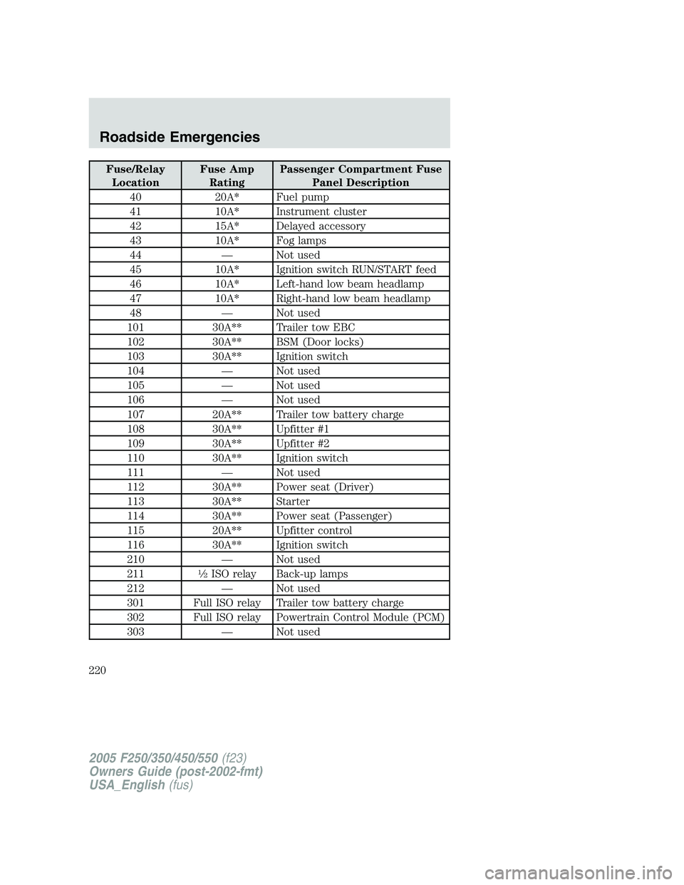
Fuse/Relay
LocationFuse Amp
RatingPassenger Compartment Fuse
Panel Description
40 20A* Fuel pump
41 10A* Instrument cluster
42 15A* Delayed accessory
43 10A* Fog lamps
44 — Not used
45 10A* Ignition switch RUN/START feed
46 10A* Left-hand low beam headlamp
47 10A* Right-hand low beam headlamp
48 — Not used
101 30A** Trailer tow EBC
102 30A** BSM (Door locks)
103 30A** Ignition switch
104 — Not used
105 — Not used
106 — Not used
107 20A** Trailer tow battery charge
108 30A** Upfitter #1
109 30A** Upfitter #2
110 30A** Ignition switch
111 — Not used
112 30A** Power seat (Driver)
113 30A** Starter
114 30A** Power seat (Passenger)
115 20A** Upfitter control
116 30A** Ignition switch
210 — Not used
211
1�2ISO relay Back-up lamps
212 — Not used
301 Full ISO relay Trailer tow battery charge
302 Full ISO relay Powertrain Control Module (PCM)
303 — Not used
2005 F250/350/450/550(f23)
Owners Guide (post-2002-fmt)
USA_English(fus)
Roadside Emergencies
220