FORD F250 2008 Owners Manual
Manufacturer: FORD, Model Year: 2008, Model line: F250, Model: FORD F250 2008Pages: 400, PDF Size: 3.5 MB
Page 231 of 400
3. Press and hold the brake pedal for two (2) seconds, then release.
4. Turn the ignition to OFF/LOCK (DO NOTremove the key.)
5. Cycle the ignition from OFF/LOCK to RUN three (3) times ending in
RUN.DO NOTstart the engine.
If reset mode has been entered successfully, the horn will sound once,
the TPMS indicator will flash and the message center will displayTRAIN
LF TIRE.
If after repeated attempts to enter reset mode, the horn does not sound,
the TPMS indicator does not flash and the message center does not
display TRAIN LF TIRE, seek service from your authorized dealer.
TPMS reset sequence
The TPMS system needs to be reset starting with the left front tire in
the following clockwise order:
1. Left front tire
2. Right front tire
3. Right rear tire
4. Left rear tire
2008 F-250/350/450/550(f23)
Owners Guide (post-2002-fmt)
USA(fus)
Tires, Wheels and Loading
231
Page 232 of 400
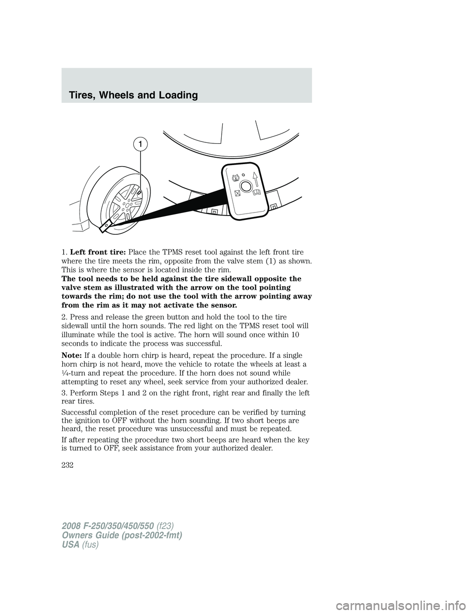
1.Left front tire:Place the TPMS reset tool against the left front tire
where the tire meets the rim, opposite from the valve stem (1) as shown.
This is where the sensor is located inside the rim.
The tool needs to be held against the tire sidewall opposite the
valve stem as illustrated with the arrow on the tool pointing
towards the rim; do not use the tool with the arrow pointing away
from the rim as it may not activate the sensor.
2. Press and release the green button and hold the tool to the tire
sidewall until the horn sounds. The red light on the TPMS reset tool will
illuminate while the tool is active. The horn will sound once within 10
seconds to indicate the process was successful.
Note:If a double horn chirp is heard, repeat the procedure. If a single
horn chirp is not heard, move the vehicle to rotate the wheels at least a
1�4-turn and repeat the procedure. If the horn does not sound while
attempting to reset any wheel, seek service from your authorized dealer.
3. Perform Steps 1 and 2 on the right front, right rear and finally the left
rear tires.
Successful completion of the reset procedure can be verified by turning
the ignition to OFF without the horn sounding. If two short beeps are
heard, the reset procedure was unsuccessful and must be repeated.
If after repeating the procedure two short beeps are heard when the key
is turned to OFF, seek assistance from your authorized dealer.
2008 F-250/350/450/550(f23)
Owners Guide (post-2002-fmt)
USA(fus)
Tires, Wheels and Loading
232
Page 233 of 400
Rotation, pressure adjustment and TPMS reset example
The following example describes all the major steps involved in rotating
tires on a vehicle with different front and rear tire pressures. It
illustrates that the TPMS reset procedure needs to follow tire rotation
and pressure adjustment to avoid a possible false low tire warning.
Example:
A particular vehicle has the following recommended tire pressures: 50 psi
(345 kPa) front; 80 psi (552 kPa) rear.
Note:For your vehicle’s pressure, refer to the Safety Compliance
Certification Label located on the B-Pillar or the edge of your vehicle’s
driver’s door.
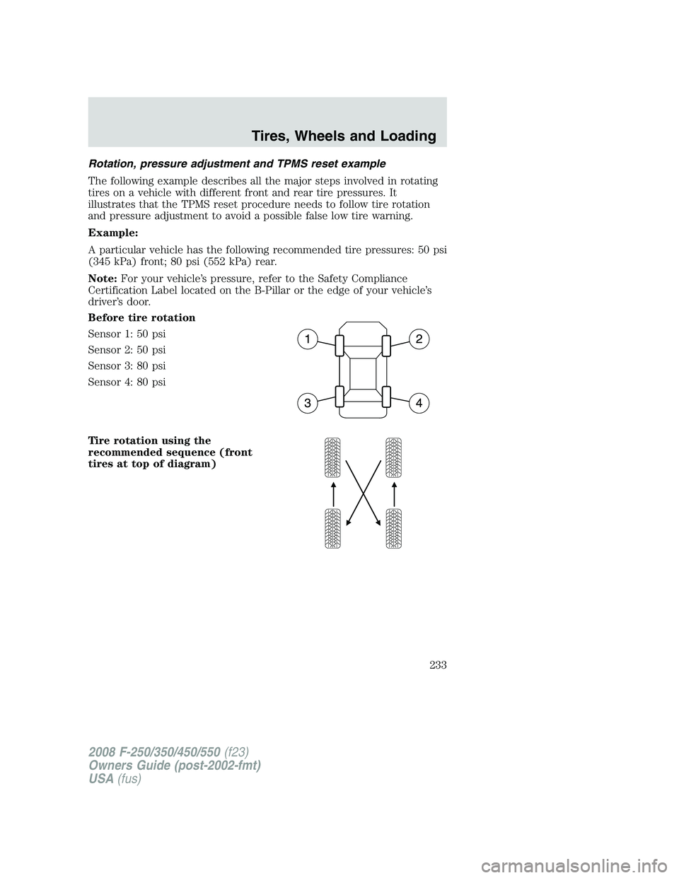
Before tire rotation
Sensor 1: 50 psi
Sensor 2: 50 psi
Sensor 3: 80 psi
Sensor 4: 80 psi
Tire rotation using the
recommended sequence (front
tires at top of diagram)
2008 F-250/350/450/550(f23)
Owners Guide (post-2002-fmt)
USA(fus)
Tires, Wheels and Loading
233
Page 234 of 400
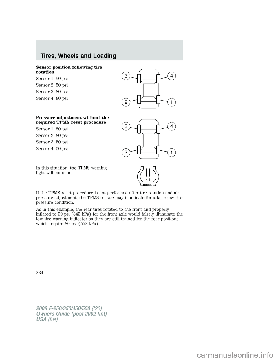
Sensor position following tire
rotation
Sensor 1: 50 psi
Sensor 2: 50 psi
Sensor 3: 80 psi
Sensor 4: 80 psi
Pressure adjustment without the
required TPMS reset procedure
Sensor 1: 80 psi
Sensor 2: 80 psi
Sensor 3: 50 psi
Sensor 4: 50 psi
In this situation, the TPMS warning
light will come on.
If the TPMS reset procedure is not performed after tire rotation and air
pressure adjustment, the TPMS telltale may illuminate for a false low tire
pressure condition.
As in this example, the rear tires rotated to the front and properly
inflated to 50 psi (345 kPa) for the front axle would falsely illuminate the
low tire warning indicator as they are still trained for the rear positions
which require 80 psi (552 kPa).
2008 F-250/350/450/550(f23)
Owners Guide (post-2002-fmt)
USA(fus)
Tires, Wheels and Loading
234
Page 235 of 400
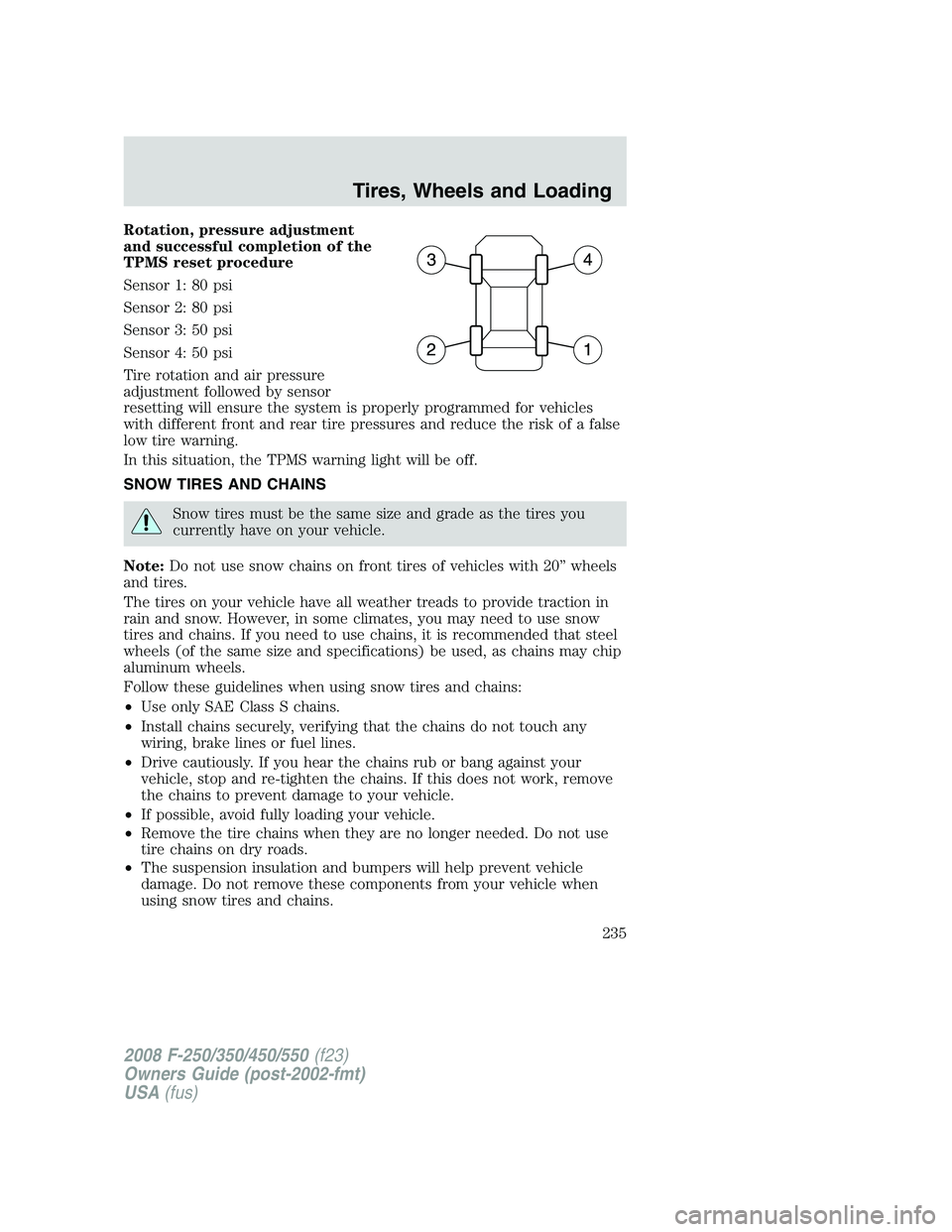
Rotation, pressure adjustment
and successful completion of the
TPMS reset procedure
Sensor 1: 80 psi
Sensor 2: 80 psi
Sensor 3: 50 psi
Sensor 4: 50 psi
Tire rotation and air pressure
adjustment followed by sensor
resetting will ensure the system is properly programmed for vehicles
with different front and rear tire pressures and reduce the risk of a false
low tire warning.
In this situation, the TPMS warning light will be off.
SNOW TIRES AND CHAINS
Snow tires must be the same size and grade as the tires you
currently have on your vehicle.
Note:Do not use snow chains on front tires of vehicles with 20” wheels
and tires.
The tires on your vehicle have all weather treads to provide traction in
rain and snow. However, in some climates, you may need to use snow
tires and chains. If you need to use chains, it is recommended that steel
wheels (of the same size and specifications) be used, as chains may chip
aluminum wheels.
Follow these guidelines when using snow tires and chains:
•Use only SAE Class S chains.
•Install chains securely, verifying that the chains do not touch any
wiring, brake lines or fuel lines.
•Drive cautiously. If you hear the chains rub or bang against your
vehicle, stop and re-tighten the chains. If this does not work, remove
the chains to prevent damage to your vehicle.
•If possible, avoid fully loading your vehicle.
•Remove the tire chains when they are no longer needed. Do not use
tire chains on dry roads.
•The suspension insulation and bumpers will help prevent vehicle
damage. Do not remove these components from your vehicle when
using snow tires and chains.
2008 F-250/350/450/550(f23)
Owners Guide (post-2002-fmt)
USA(fus)
Tires, Wheels and Loading
235
Page 236 of 400
VEHICLE LOADING – WITH AND WITHOUT A TRAILER
This section will guide you in the proper loading of your vehicle and/or
trailer, to keep your loaded vehicle weight within its design rating
capability, with or without a trailer. Properly loading your vehicle will
provide maximum return of vehicle design performance. Before loading
your vehicle, familiarize yourself with the following terms for determining
your vehicle’s weight ratings, with or without a trailer, from the vehicle’s
Tire Label or Safety Compliance Certification Label:
Base Curb Weight– is the weight of the vehicle including a full tank of
fuel and all standard equipment. It does not include passengers, cargo, or
optional equipment.
Vehicle Curb Weight– is the weight of your new vehicle when you
picked it up from your authorized dealer plus any aftermarket
equipment.
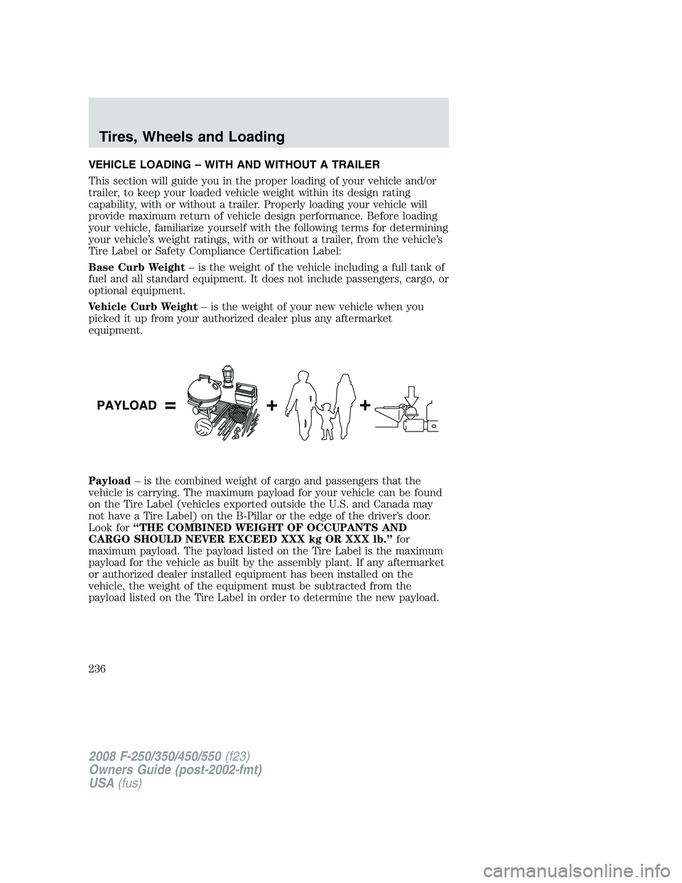
Payload– is the combined weight of cargo and passengers that the
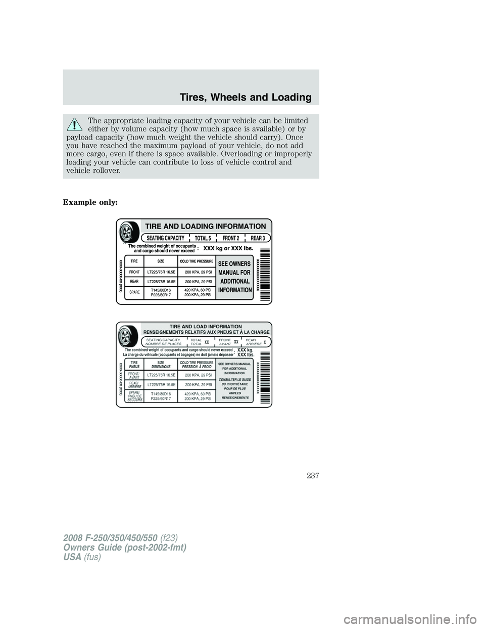
vehicle is carrying. The maximum payload for your vehicle can be found
on the Tire Label (vehicles exported outside the U.S. and Canada may
not have a Tire Label) on the B-Pillar or the edge of the driver’s door.
Look for“THE COMBINED WEIGHT OF OCCUPANTS AND
CARGO SHOULD NEVER EXCEED XXX kg OR XXX lb.”for
maximum payload. The payload listed on the Tire Label is the maximum
payload for the vehicle as built by the assembly plant. If any aftermarket
or authorized dealer installed equipment has been installed on the
vehicle, the weight of the equipment must be subtracted from the
payload listed on the Tire Label in order to determine the new payload.
2008 F-250/350/450/550(f23)
Owners Guide (post-2002-fmt)
USA(fus)
Tires, Wheels and Loading
236
Page 237 of 400
The appropriate loading capacity of your vehicle can be limited
either by volume capacity (how much space is available) or by
payload capacity (how much weight the vehicle should carry). Once
you have reached the maximum payload of your vehicle, do not add
more cargo, even if there is space available. Overloading or improperly
loading your vehicle can contribute to loss of vehicle control and
vehicle rollover.
Example only:
2008 F-250/350/450/550(f23)
Owners Guide (post-2002-fmt)
USA(fus)
Tires, Wheels and Loading
237
Page 238 of 400
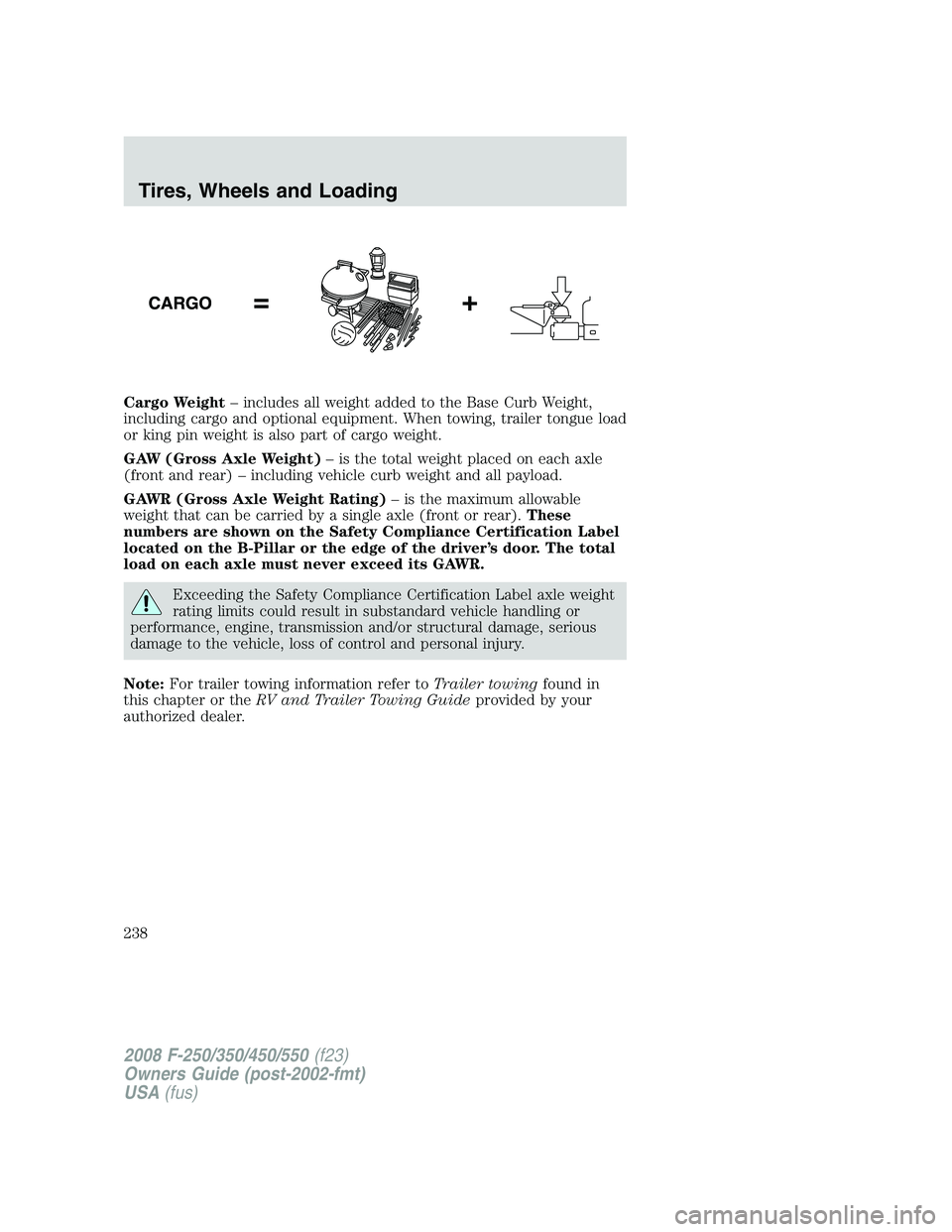
Cargo Weight– includes all weight added to the Base Curb Weight,
including cargo and optional equipment. When towing, trailer tongue load
or king pin weight is also part of cargo weight.
GAW (Gross Axle Weight)– is the total weight placed on each axle
(front and rear) – including vehicle curb weight and all payload.
GAWR (Gross Axle Weight Rating)– is the maximum allowable
weight that can be carried by a single axle (front or rear).These
numbers are shown on the Safety Compliance Certification Label
located on the B-Pillar or the edge of the driver’s door. The total
load on each axle must never exceed its GAWR.
Exceeding the Safety Compliance Certification Label axle weight
rating limits could result in substandard vehicle handling or
performance, engine, transmission and/or structural damage, serious
damage to the vehicle, loss of control and personal injury.
Note:For trailer towing information refer toTrailer towingfound in
this chapter or theRV and Trailer Towing Guideprovided by your
authorized dealer.
2008 F-250/350/450/550(f23)
Owners Guide (post-2002-fmt)
USA(fus)
Tires, Wheels and Loading
238
Page 239 of 400
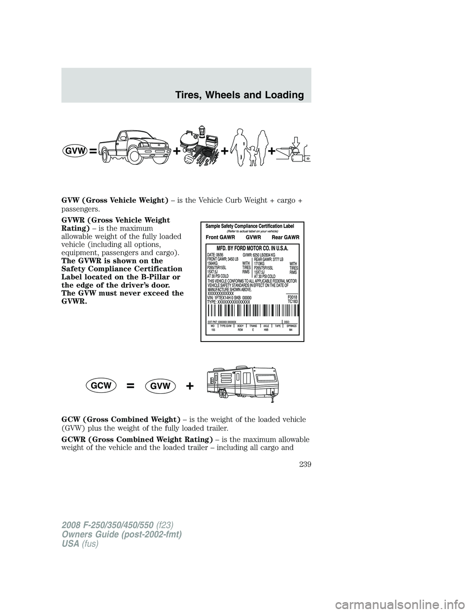
GVW (Gross Vehicle Weight)– is the Vehicle Curb Weight + cargo +
passengers.
GVWR (Gross Vehicle Weight
Rating)– is the maximum
allowable weight of the fully loaded
vehicle (including all options,
equipment, passengers and cargo).
The GVWR is shown on the
Safety Compliance Certification
Label located on the B-Pillar or
the edge of the driver’s door.
The GVW must never exceed the
GVWR.
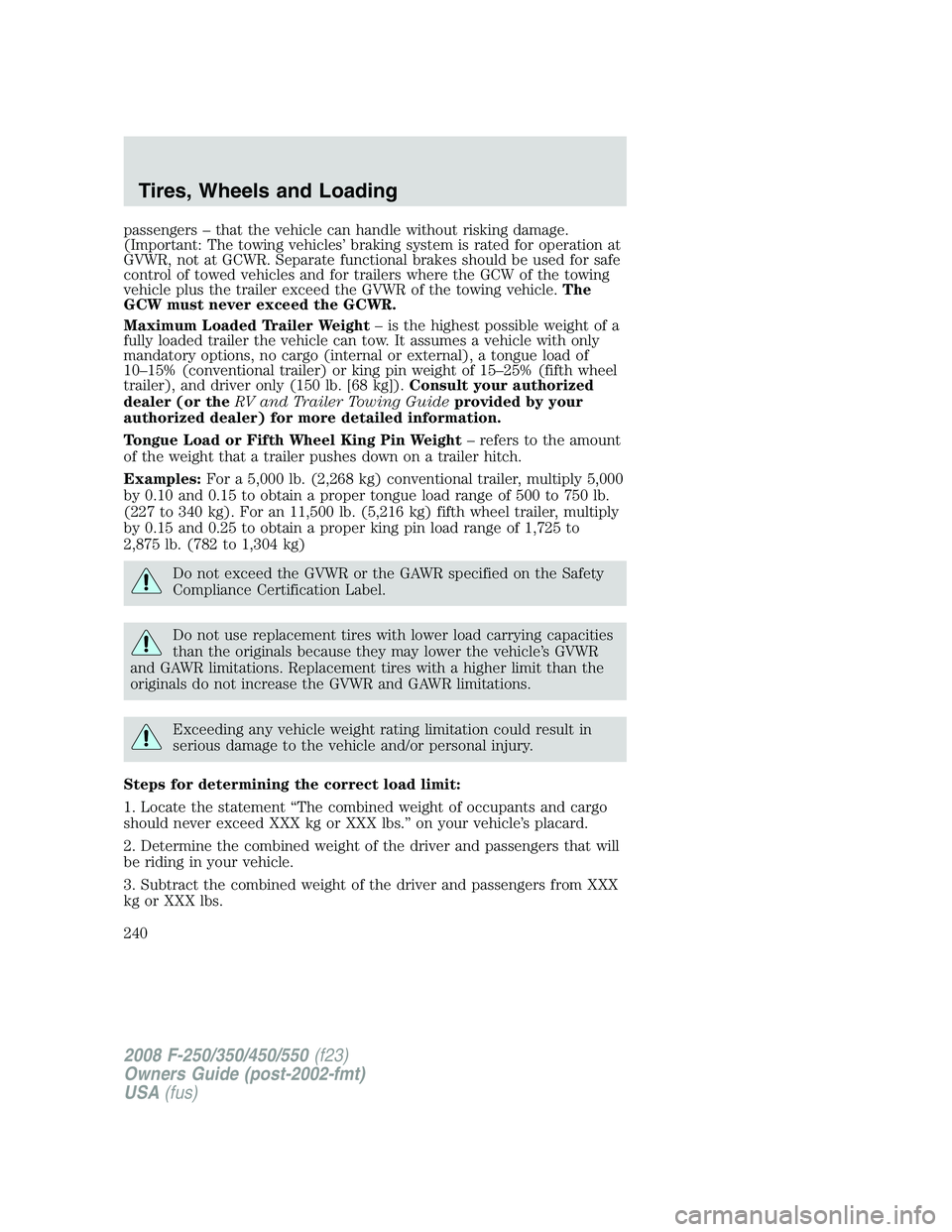
GCW (Gross Combined Weight)– is the weight of the loaded vehicle
(GVW) plus the weight of the fully loaded trailer.
GCWR (Gross Combined Weight Rating)– is the maximum allowable
weight of the vehicle and the loaded trailer – including all cargo and
2008 F-250/350/450/550(f23)
Owners Guide (post-2002-fmt)
USA(fus)
Tires, Wheels and Loading
239
Page 240 of 400
passengers – that the vehicle can handle without risking damage.
(Important: The towing vehicles’ braking system is rated for operation at
GVWR, not at GCWR. Separate functional brakes should be used for safe
control of towed vehicles and for trailers where the GCW of the towing
vehicle plus the trailer exceed the GVWR of the towing vehicle.The
GCW must never exceed the GCWR.
Maximum Loaded Trailer Weight– is the highest possible weight of a
fully loaded trailer the vehicle can tow. It assumes a vehicle with only
mandatory options, no cargo (internal or external), a tongue load of
10–15% (conventional trailer) or king pin weight of 15–25% (fifth wheel
trailer), and driver only (150 lb. [68 kg]).Consult your authorized
dealer (or theRV and Trailer Towing Guideprovided by your
authorized dealer) for more detailed information.
Tongue Load or Fifth Wheel King Pin Weight– refers to the amount
of the weight that a trailer pushes down on a trailer hitch.
Examples:For a 5,000 lb. (2,268 kg) conventional trailer, multiply 5,000
by 0.10 and 0.15 to obtain a proper tongue load range of 500 to 750 lb.
(227 to 340 kg). For an 11,500 lb. (5,216 kg) fifth wheel trailer, multiply
by 0.15 and 0.25 to obtain a proper king pin load range of 1,725 to
2,875 lb. (782 to 1,304 kg)
Do not exceed the GVWR or the GAWR specified on the Safety
Compliance Certification Label.
Do not use replacement tires with lower load carrying capacities
than the originals because they may lower the vehicle’s GVWR
and GAWR limitations. Replacement tires with a higher limit than the
originals do not increase the GVWR and GAWR limitations.
Exceeding any vehicle weight rating limitation could result in
serious damage to the vehicle and/or personal injury.
Steps for determining the correct load limit:
1. Locate the statement “The combined weight of occupants and cargo
should never exceed XXX kg or XXX lbs.” on your vehicle’s placard.
2. Determine the combined weight of the driver and passengers that will
be riding in your vehicle.
3. Subtract the combined weight of the driver and passengers from XXX
kg or XXX lbs.
2008 F-250/350/450/550(f23)
Owners Guide (post-2002-fmt)
USA(fus)
Tires, Wheels and Loading
240