tailgate FORD F250 2011 Owners Manual
[x] Cancel search | Manufacturer: FORD, Model Year: 2011, Model line: F250, Model: FORD F250 2011Pages: 449, PDF Size: 3.38 MB
Page 94 of 449
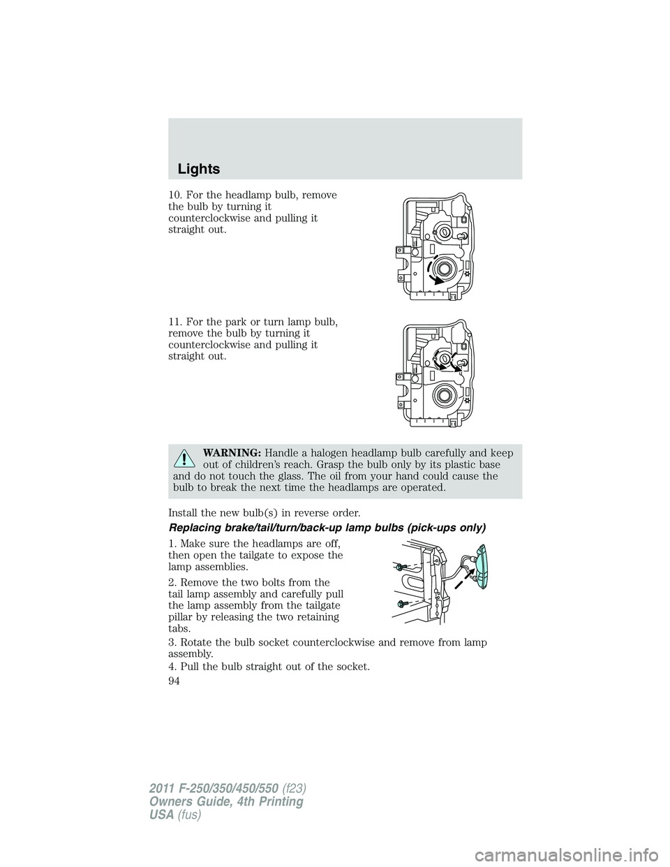
10. For the headlamp bulb, remove
the bulb by turning it
counterclockwise and pulling it
straight out.
11. For the park or turn lamp bulb,
remove the bulb by turning it
counterclockwise and pulling it
straight out.
WARNING:Handle a halogen headlamp bulb carefully and keep
out of children’s reach. Grasp the bulb only by its plastic base
and do not touch the glass. The oil from your hand could cause the
bulb to break the next time the headlamps are operated.
Install the new bulb(s) in reverse order.
Replacing brake/tail/turn/back-up lamp bulbs (pick-ups only)
1. Make sure the headlamps are off,
then open the tailgate to expose the
lamp assemblies.
2. Remove the two bolts from the
tail lamp assembly and carefully pull
the lamp assembly from the tailgate
pillar by releasing the two retaining
tabs.
3. Rotate the bulb socket counterclockwise and remove from lamp
assembly.
4. Pull the bulb straight out of the socket.
Lights
94
2011 F-250/350/450/550(f23)
Owners Guide, 4th Printing
USA(fus)
Page 121 of 449
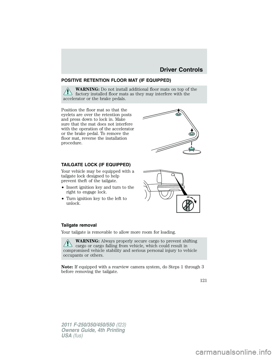
POSITIVE RETENTION FLOOR MAT (IF EQUIPPED)
WARNING:Do not install additional floor mats on top of the
factory installed floor mats as they may interfere with the
accelerator or the brake pedals.
Position the floor mat so that the
eyelets are over the retention posts
and press down to lock in. Make
sure that the mat does not interfere
with the operation of the accelerator
or the brake pedal. To remove the
floor mat, reverse the installation
procedure.
TAILGATE LOCK (IF EQUIPPED)
Your vehicle may be equipped with a
tailgate lock designed to help
prevent theft of the tailgate.
•Insert ignition key and turn to the
right to engage lock.
•Turn ignition key to the left to
unlock.
Tailgate removal
Your tailgate is removable to allow more room for loading.
WARNING:Always properly secure cargo to prevent shifting
cargo or cargo falling from vehicle, which could result in
compromised vehicle stability and serious personal injury to vehicle
occupants or others.
Note:If equipped with a rearview camera system, do Steps 1 through 3
before removing the tailgate.
Driver Controls
121
2011 F-250/350/450/550(f23)
Owners Guide, 4th Printing
USA(fus)
Page 122 of 449
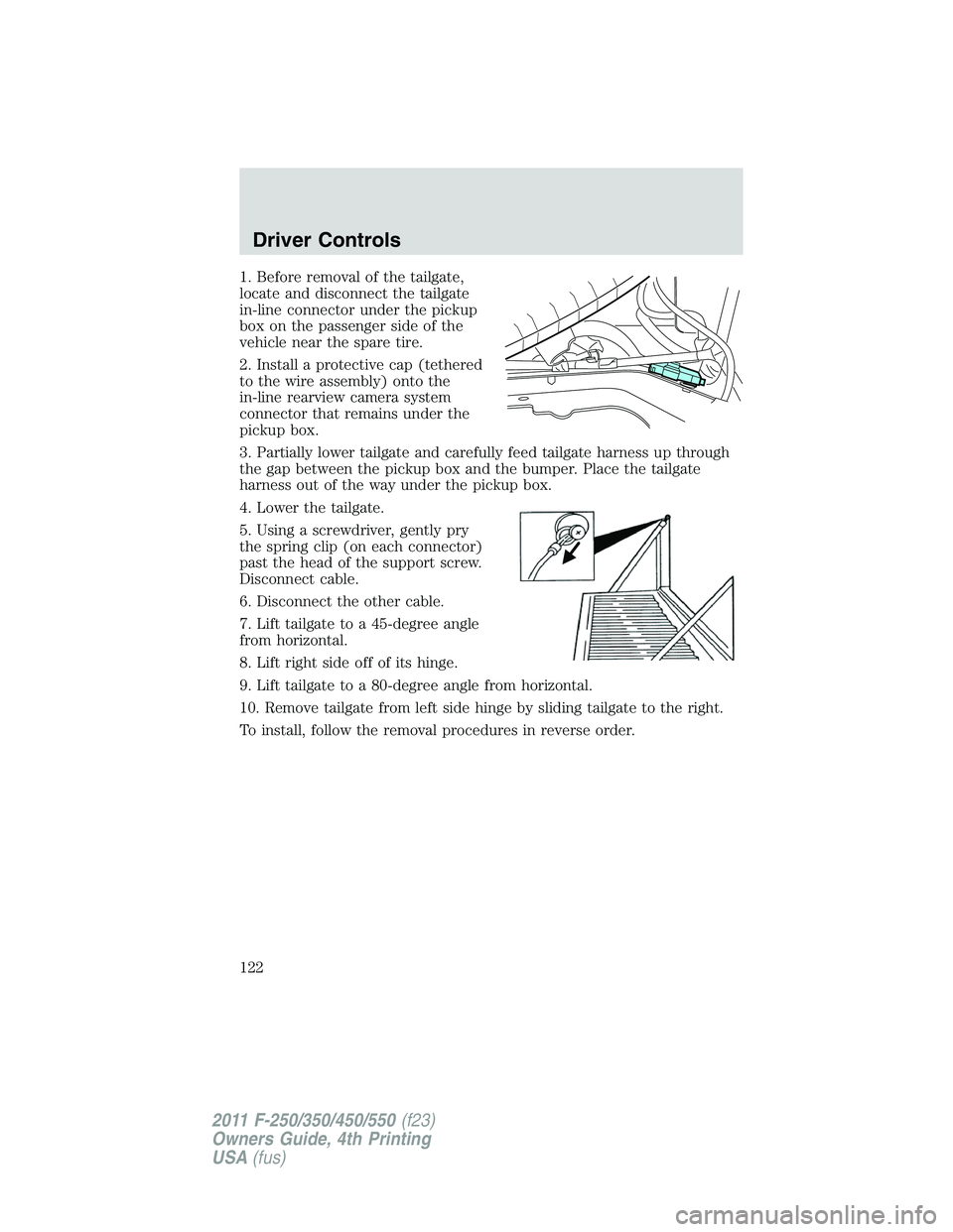
1. Before removal of the tailgate,
locate and disconnect the tailgate
in-line connector under the pickup
box on the passenger side of the
vehicle near the spare tire.
2. Install a protective cap (tethered
to the wire assembly) onto the
in-line rearview camera system
connector that remains under the
pickup box.
3. Partially lower tailgate and carefully feed tailgate harness up through
the gap between the pickup box and the bumper. Place the tailgate
harness out of the way under the pickup box.
4. Lower the tailgate.
5. Using a screwdriver, gently pry
the spring clip (on each connector)
past the head of the support screw.
Disconnect cable.
6. Disconnect the other cable.
7. Lift tailgate to a 45-degree angle
from horizontal.
8. Lift right side off of its hinge.
9. Lift tailgate to a 80-degree angle from horizontal.
10. Remove tailgate from left side hinge by sliding tailgate to the right.
To install, follow the removal procedures in reverse order.
Driver Controls
122
2011 F-250/350/450/550(f23)
Owners Guide, 4th Printing
USA(fus)
Page 123 of 449
Tailgate step (if equipped)
Your vehicle may be equipped with a feature that allows easier entry into
the truck bed. To open the tailgate step:
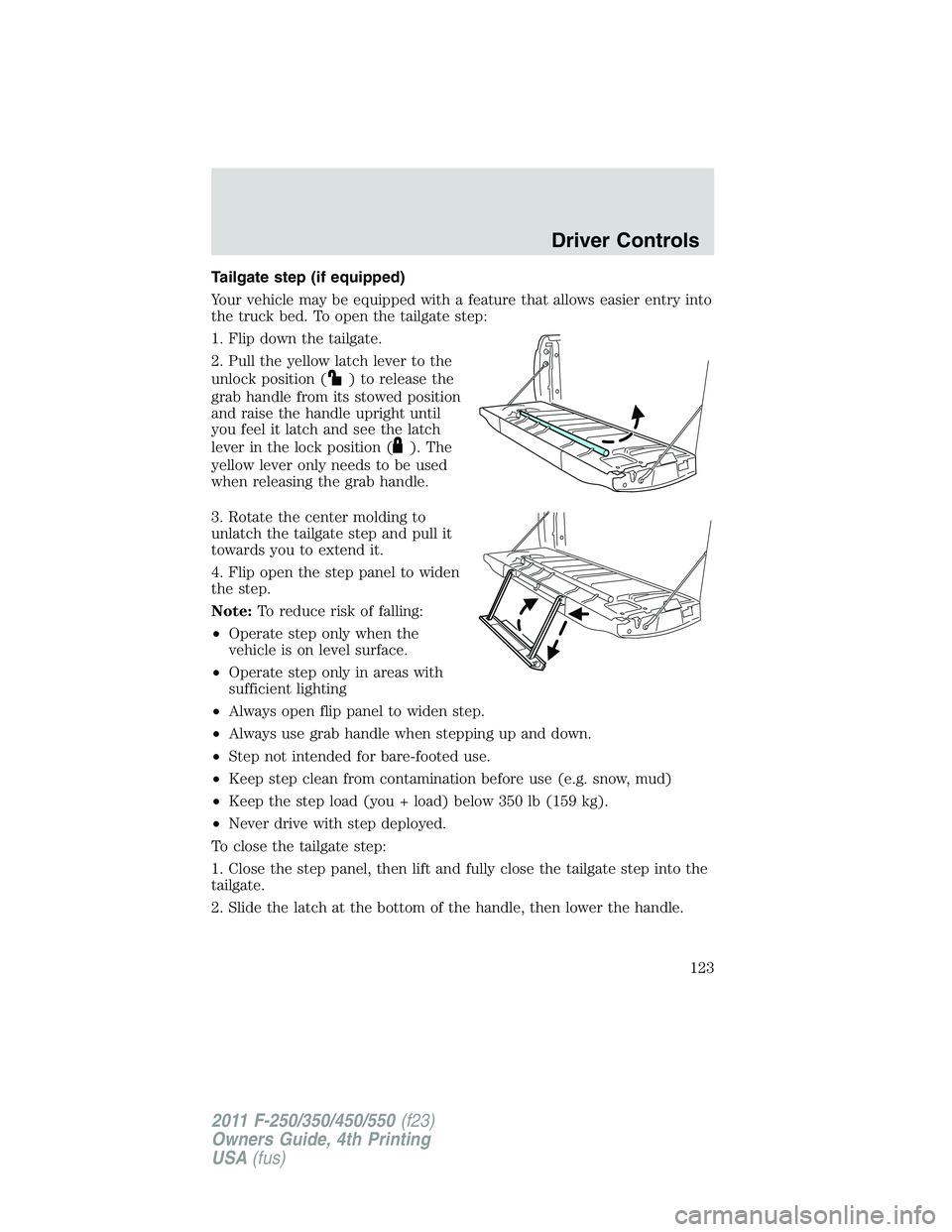
1. Flip down the tailgate.
2. Pull the yellow latch lever to the
unlock position (
) to release the
grab handle from its stowed position
and raise the handle upright until
you feel it latch and see the latch
lever in the lock position (
). The
yellow lever only needs to be used
when releasing the grab handle.
3. Rotate the center molding to
unlatch the tailgate step and pull it
towards you to extend it.
4. Flip open the step panel to widen
the step.
Note:To reduce risk of falling:
•Operate step only when the
vehicle is on level surface.
•Operate step only in areas with
sufficient lighting
•Always open flip panel to widen step.
•Always use grab handle when stepping up and down.
•Step not intended for bare-footed use.
•Keep step clean from contamination before use (e.g. snow, mud)
•Keep the step load (you + load) below 350 lb (159 kg).
•Never drive with step deployed.
To close the tailgate step:
1. Close the step panel, then lift and fully close the tailgate step into the
tailgate.
2. Slide the latch at the bottom of the handle, then lower the handle.
Driver Controls
123
2011 F-250/350/450/550(f23)
Owners Guide, 4th Printing
USA(fus)
Page 124 of 449
Note:
•Fully close and latch the tailgate step before moving the vehicle.
•Never drive with the step or grab handle deployed.
•Replace slip resistance tape (serviceable item) if worn out.
•Replace handle molding (serviceable item) if damaged.
•Do not tow with grab handle or step frame.
Bed extender (if equipped)
Your vehicle may be equipped with a cargo management feature in the
truck bed.
Note:This feature is not intended for off-road usage.
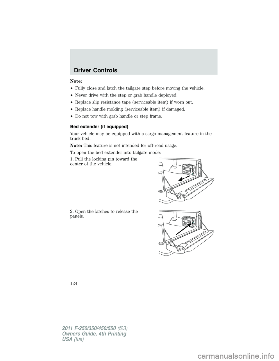
To open the bed extender into tailgate mode:
1. Pull the locking pin toward the
center of the vehicle.
2. Open the latches to release the
panels.
Driver Controls
124
2011 F-250/350/450/550(f23)
Owners Guide, 4th Printing
USA(fus)
Page 125 of 449
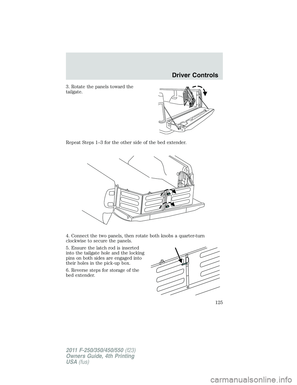
3. Rotate the panels toward the
tailgate.
Repeat Steps 1–3 for the other side of the bed extender.
4. Connect the two panels, then rotate both knobs a quarter-turn
clockwise to secure the panels.
5. Ensure the latch rod is inserted
into the tailgate hole and the locking
pins on both sides are engaged into
their holes in the pick-up box.
6. Reverse steps for storage of the
bed extender.
Driver Controls
125
2011 F-250/350/450/550(f23)
Owners Guide, 4th Printing
USA(fus)
Page 126 of 449
Note:When the vehicle is in motion, ensure the locking pins and knobs
are fully engaged.
Note:Ensure all cargo is secured.
Note:When the vehicle is in motion, the tailgate load must not exceed
150 lb (68 kg).
Note:The bed extender should always be kept in the grocery mode or
stowed position with the tailgate closed when not being used for the
purpose of restraining cargo in the tailgate mode.
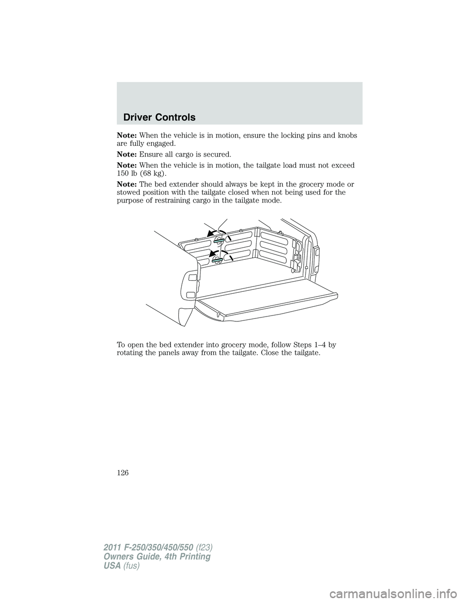
To open the bed extender into grocery mode, follow Steps 1–4 by
rotating the panels away from the tailgate. Close the tailgate.
Driver Controls
126
2011 F-250/350/450/550(f23)
Owners Guide, 4th Printing
USA(fus)
Page 293 of 449
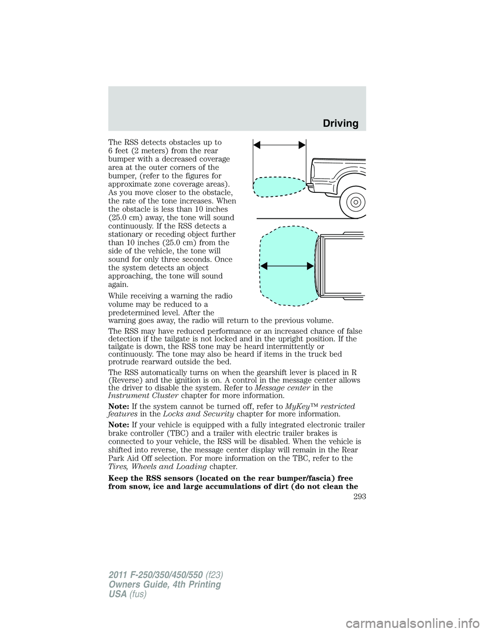
The RSS detects obstacles up to
6 feet (2 meters) from the rear
bumper with a decreased coverage
area at the outer corners of the
bumper, (refer to the figures for
approximate zone coverage areas).
As you move closer to the obstacle,
the rate of the tone increases. When
the obstacle is less than 10 inches
(25.0 cm) away, the tone will sound
continuously. If the RSS detects a
stationary or receding object further
than 10 inches (25.0 cm) from the
side of the vehicle, the tone will
sound for only three seconds. Once
the system detects an object
approaching, the tone will sound
again.
While receiving a warning the radio
volume may be reduced to a
predetermined level. After the
warning goes away, the radio will return to the previous volume.
The RSS may have reduced performance or an increased chance of false
detection if the tailgate is not locked and in the upright position. If the
tailgate is down, the RSS tone may be heard intermittently or
continuously. The tone may also be heard if items in the truck bed
protrude rearward outside the bed.
The RSS automatically turns on when the gearshift lever is placed in R
(Reverse) and the ignition is on. A control in the message center allows
the driver to disable the system. Refer toMessage centerin the
Instrument Clusterchapter for more information.
Note:If the system cannot be turned off, refer toMyKey™ restricted
featuresin theLocks and Securitychapter for more information.
Note:If your vehicle is equipped with a fully integrated electronic trailer
brake controller (TBC) and a trailer with electric trailer brakes is
connected to your vehicle, the RSS will be disabled. When the vehicle is
shifted into reverse, the message center display will remain in the Rear
Park Aid Off selection. For more information on the TBC, refer to the
Tires, Wheels and Loadingchapter.
Keep the RSS sensors (located on the rear bumper/fascia) free
from snow, ice and large accumulations of dirt (do not clean the
Driving
293
2011 F-250/350/450/550(f23)
Owners Guide, 4th Printing
USA(fus)
Page 294 of 449
sensors with sharp objects). If the sensors are covered, it will
affect the accuracy of the RSS.
If your vehicle sustains damage to the rear bumper/fascia, leaving
it misaligned or bent, the sensing zone may be altered causing
inaccurate measurement of obstacles or false alarms.
REARVIEW CAMERA SYSTEM (IF EQUIPPED)
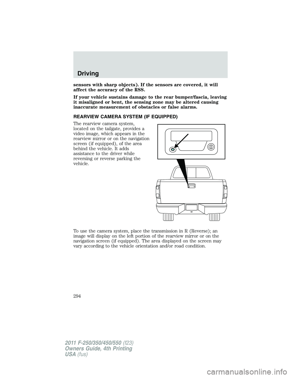
The rearview camera system,
located on the tailgate, provides a
video image, which appears in the
rearview mirror or on the navigation
screen (if equipped), of the area
behind the vehicle. It adds
assistance to the driver while
reversing or reverse parking the
vehicle.
To use the camera system, place the transmission in R (Reverse); an
image will display on the left portion of the rearview mirror or on the
navigation screen (if equipped). The area displayed on the screen may
vary according to the vehicle orientation and/or road condition.
Driving
294
2011 F-250/350/450/550(f23)
Owners Guide, 4th Printing
USA(fus)
Page 295 of 449
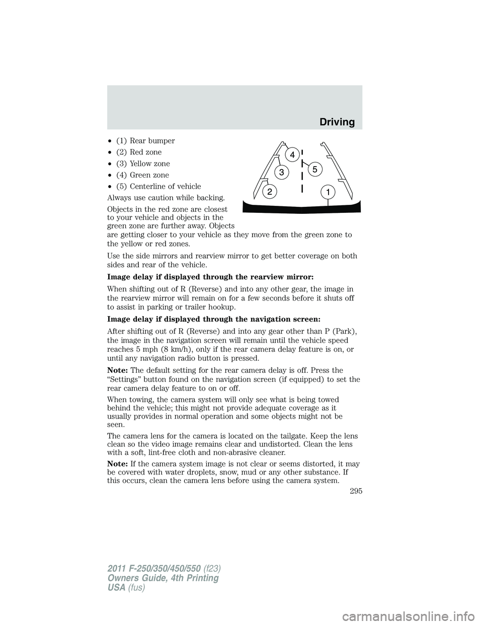
•(1) Rear bumper
•(2) Red zone
•(3) Yellow zone
•(4) Green zone
•(5) Centerline of vehicle
Always use caution while backing.
Objects in the red zone are closest
to your vehicle and objects in the
green zone are further away. Objects
are getting closer to your vehicle as they move from the green zone to
the yellow or red zones.
Use the side mirrors and rearview mirror to get better coverage on both
sides and rear of the vehicle.
Image delay if displayed through the rearview mirror:
When shifting out of R (Reverse) and into any other gear, the image in
the rearview mirror will remain on for a few seconds before it shuts off
to assist in parking or trailer hookup.
Image delay if displayed through the navigation screen:
After shifting out of R (Reverse) and into any gear other than P (Park),
the image in the navigation screen will remain until the vehicle speed
reaches 5 mph (8 km/h), only if the rear camera delay feature is on, or
until any navigation radio button is pressed.
Note:The default setting for the rear camera delay is off. Press the
“Settings” button found on the navigation screen (if equipped) to set the
rear camera delay feature to on or off.
When towing, the camera system will only see what is being towed
behind the vehicle; this might not provide adequate coverage as it
usually provides in normal operation and some objects might not be
seen.
The camera lens for the camera is located on the tailgate. Keep the lens
clean so the video image remains clear and undistorted. Clean the lens
with a soft, lint-free cloth and non-abrasive cleaner.
Note:If the camera system image is not clear or seems distorted, it may
be covered with water droplets, snow, mud or any other substance. If
this occurs, clean the camera lens before using the camera system.
Driving
295
2011 F-250/350/450/550(f23)
Owners Guide, 4th Printing
USA(fus)